
Table 1.
Transmitter design parameters.
| Parameter | Value/description |
|---|---|
| Transmission band | 1,540-1,549.9 nm |
| Channel spacing | 0.1 nm |
| Optical transmission power | 0.1-1 mW |
| Optical modulation | External modulation (Mach–Zehnder modulator) |
| Data transmission rate | 40 Gbps |
| Transmission medium | Single-mode fiber (SMF) |
| Total channels | 100 |
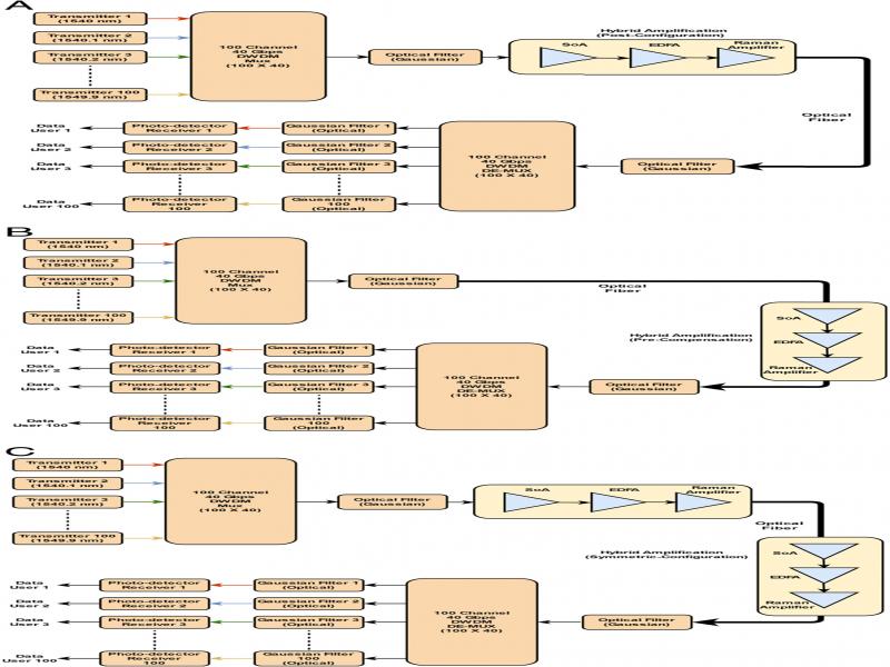
Figure 1:
Proposed high-speed DWDM link with a hybrid amplifier positioned in (A) post-, (B) pre-, and (C) symmetric configuration.
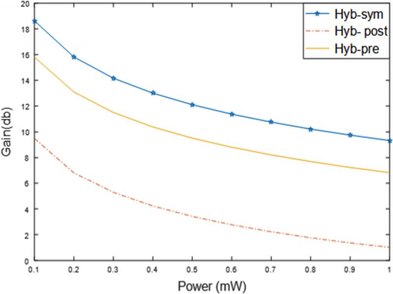
Figure 2:
Analysis of power versus gain for symmetric, post-, and preamplifier configurations using a hybrid (SOA, EDFA, and Raman) amplifier.
Table 2.
Amplifier and receiver design parameters.
| Parameter | Value/description |
|---|---|
| Injection current (SOA) | 0.05 Amp |
| Length—EDFA | 50 meters |
| Length—Raman amplifier | 10 kms |
| Pump power—EDFA | 300 mW (forward type) |
| Pump signal—wavelength | 980 nm |
| Pump power—Raman amplifier | 100 mW |
| Detector type | PIN |
| SMF attenuation (@1550 nm) | 0.2 dB/km |
Table 3.
Gain (dB) comparison of hybrid and nonhybrid amplifier for different values of transmission power.
| Hybrid amplifier | Nonhybrid amplifier | |||||
|---|---|---|---|---|---|---|
| Transmission power | Pre- | Post- | Symmetric- | Pre- | Post- | Symmetric- |
| 0.1 mW | 15.8 | 9.4 | 18.6 | −4.7 | −4.8 | −2.6 |
| 1 mW | 6.8 | 1 | 9.3 | −4.9 | −5.6 | −3.7 |
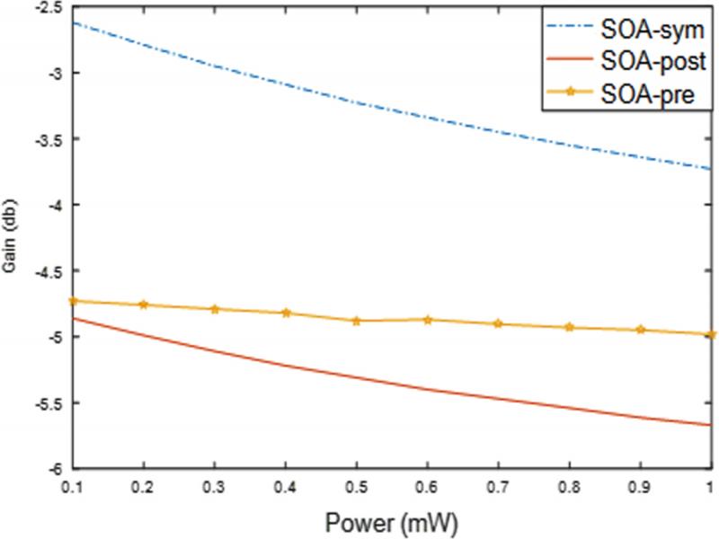
Figure 4:
Analysis of BER and length using a hybrid amplifier for pre-, post-, and symmetric configurations.
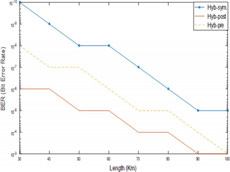
Figure 5:
Analysis of wavelength versus gain for hybrid and SOA in symmetric, pre-, and post-amplifier configurations.
Table 4.
BER comparison at different link range (kms).
| Link range | |||
|---|---|---|---|
| Configuration | 50 km | 70 km | 100 km |
| Pre- | 10−7 | 10−5 | 10−3 |
| Post- | 10−5 | 10−4 | 10−2 |
| Symmetric- | 10−8 | 10−7 | 10−5 |
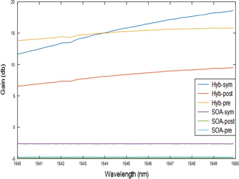
Figure 3:
Analysis of power versus gain for symmetric, post-, and preamplifier configurations using SOA.