Rapid expansion of mobile services, tech-savvy lifestyle, e-commerce, and digital literacy are some of the key forces that have led to the creation of an enormous market for data service providers. However, fulfilling this ever-increasing data hunger will not be possible without incorporating communication technologies that can provide cost-effective high-speed data access to the end users. Radio infrastructure (RF) today forms the major backbone for data connectivity services, but it is highly likely that the current RF regime will witness massive performance-deficient systems in the near future (Miglani et al., 2020b; Sharma and Sharma, 2016; Kumar et al., 2020). Lightwave communication links due to their large bandwidth and the ability to support high-speed data access will play a crucial role in the success of creating a digital world (Kumar et al., 2019). In order to utilize the bandwidth of the fiber more effectively and to make the transmission of multichannels possible, an efficient technique called wavelength division multiplexing (WDM) was introduced (Ivaniga et al., 2016; Chowdhury et al., 2019; Ji et al., 2019; Miglani et al., 2019). The transmitter section of WDM uses N:1 multiplexer that combines incoming N optically modulated channels to a single consolidated channel. Since all of these channels have different modulation wavelengths, the receiver section uses highly capable optical demultiplexers and filters to separate the participating wavelength signals (Sharma and Sharma, 2016; Miglani et al., 2020b). Among various forms of wavelength division multiplexing, the DWDM provides the best-in-class and efficient use of the available optical bandwidth (Sharma and Sharma, 2016). DWDM systems, therefore, allow tight packing of multiple information channels separated from each other by guard space to achieve a high-capacity optical network.
Signal transmission over long distances induces various forms of losses that include path loss, absorption loss, and scattering loss, to name a few. Such losses can play havoc with an estimated power budget, thus leading to deteriorated services (Curri and Carena, 2016). Therefore, it becomes imperative to use signal-conditioning measures that can strengthen the information-bearing signals for correct detection. There are a variety of optical amplification techniques and equipment available today, which can fulfill the aforementioned requirements. Semiconductor optical amplifier (SOA) is one such example that uses an optoelectronic mechanism to boost the incoming signals. SOA possesses design elements of an antireflection coating material at the end faces. These amplifiers are characteristically made from the compound semiconductors (typically from group III to group V). Although convenient and cost-effective to use, SOAs will find themselves incompatible with new-generation all-optical networks (Miglani et al., 2020a). Erbium-doped fiber amplifier (EDFA), on the other hand, uses an all-optical amplification process obtained through the action of an external pump source that generally operates either at 980 nm or 1480 nm. An important feature of EDFA is its ability to amplify signals in the C and L bands of the optical spectrum with low noise and cross talk as compared with SOA (Srinuan and Noppanakeepong, 2013; Pedro and Costa, 2018). EDFAs are, however, limited by the requirement of a high-powered external pump, low gains beyond C and L bands, and long length of EDFA required to achieve the desired gain. Raman amplifier also uses an external pump source to induce nonlinearity to achieve amplification. Using a high-powered external pump, stimulated Raman scattering (SRS) causes transfer of power from a pump to a modulated signal. Raman amplifier offers a very dynamic feature of tailoring-achievable gain over a wide range of wavelengths, and this is in sharp contrast to EDFA that has restricted operational bandwidth (Urquhart et al., 2007; Jose and Narayanan, 2015). Raman amplifiers are however accompanied with high coupling losses and nonlinear amplification characteristics (Carena et al., 2001; Miglani et al., 2020b). Therefore, it can be decisively said that each of the amplifier mentioned here has its own set of advantages and limitations. Thus, it is for the same reason that hybrid amplifiers came into existence, and these amplifiers actually had all the favorable features of SOA, EDFA, and Raman amplifier. Such an arrangement of an amplifier has played a major role in achieving long-haul optical links with minimum signal conditioning at intermediate nodes.
Apart from designing and optimizing a hybrid amplifier, we have also investigated the performance of a proposed hybrid-amplified DWDM link for different positional configurations of the amplifier. There are possibly three different positional configurations in which the optical amplifiers can be in the photonic network, namely, pre, post, and symmetric. In pre-amplification configuration, the optical amplifier is positioned and operated right before the receiver, i.e., detection stage. This configuration is known to enhance receiver sensitivity and increased gain with the minimum addition of noise. Post-amplification configuration on the other hand allows the optical amplifier to be operated just after the transmitter section with an aim to strengthen the optical power that goes into the propagation medium. Last, symmetric-amplification configuration uses twin optical amplifiers, out of which one is used after the transmission, while the other operates before the data recovery section. Symmetric configuration delivers the best of pre- and post- amplification configuration, thus ensuring effective compensation of link losses (Carena et al., 2001; Urquhart et al., 2007; Pedro and Costa, 2018).
This paper consists of four sections. The second section examines the proposed methodology and simulation setup design features, while evaluation of the observed results has been put up in the third section. The paper is concluded with possible future scope of research in the fourth section.
Proposed methodology and link design
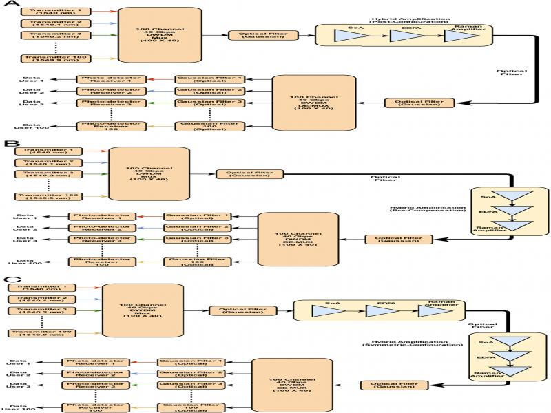
In this paper, a high-speed DWDM optical link has been examined for performance analysis with different amplification configurations as shown in Figure 1A-C. Each of these links has been designed and investigated using a specialized design tool OptiSystemTM. As mentioned previously, Figure 1A illustrates a DWDM link with post-amplification character, while Figure 1B, C highlights pre- and symmetric configurations, respectively. Irrespective of the amplification configurations, each of these links can be said to have three fundamental segments, namely, transmitter, receiver, and amplifier. The transmitter section consists of 100 different optical sources that are capable of converting the user data (electrical) to an optical modulated signal. Each of these transmitters operates at a frequency (wavelength), which is different from the other. The wavelength spacing between the optical modulators is 0.1 nm, and all the transmitters operate on a fixed wavelength that lies in the channel band, i.e., 1,540 to 1549.9 nm. As a matter of fact, this channel lies within the conventional band (C band) of the third transmission window of optical communication. Further, each transmitter modulates and conditions the data at a rate of 40 Gbps, while the transmitted optical power from each of the channels can be varied from 0.1 to 1 mW, i.e., −10 to 0 dBm, respectively. Every transmitter shown in Figures 1 and 2 uses a Mach–Zehnder modulator to perform external modulation on nonreturn to zero (NRZ)-conditioned electrical signal with the help of a continuous-wave (CW) laser that acts as an optical carrier. Later, a 100:1 optical multiplexer combines all of the optically modulated 100 channels operating between 1,540 and 1,549.9 nm onto a single channel, such that each of the channel information remains intact through predefined channel spacing. This process of packing different channels through tight interchannel spacing is known as dense wavelength division multiplexing (DWDM). The second stage in each of our designs is that of amplification as explained in previous sections; we have chosen hybrid amplification over stand-alone options as the former is capable of delivering tailored benefits that otherwise cannot be achieved using SOA, EDFA, or Raman amplifier. In our case, the performance of the proposed link has been evaluated by placing the hybrid amplifier stage in pre-, post-, and symmetric configurations (Table 1).
Table 1.
Transmitter design parameters.
| Parameter | Value/description | |||||
|---|---|---|---|---|---|---|
| Transmission band | 1,540-1,549.9 nm | |||||
| Channel spacing | 0.1 nm | |||||
| Optical transmission power | 0.1-1 mW | |||||
| Optical modulation | External modulation (Mach–Zehnder modulator) | |||||
| Data transmission rate | 40 Gbps | |||||
| Transmission medium | Single-mode fiber (SMF) | |||||
| Total channels | 100 | |||||
| Parameter | Value/description | |||||
|---|---|---|---|---|---|---|
| Injection current (SOA) | 0.05 Amp | |||||
| Length—EDFA | 50 meters | |||||
| Length—Raman amplifier | 10 kms | |||||
| Pump power—EDFA | 300 mW (forward type) | |||||
| Pump signal—wavelength | 980 nm | |||||
| Pump power—Raman amplifier | 100 mW | |||||
| Detector type | PIN | |||||
| SMF attenuation (@1550 nm) | 0.2 dB/km | |||||
| Hybrid amplifier | Nonhybrid amplifier | |||||
|---|---|---|---|---|---|---|
| Transmission power | Pre- | Post- | Symmetric- | Pre- | Post- | Symmetric- |
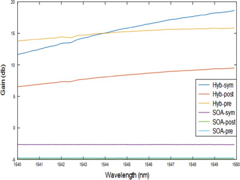
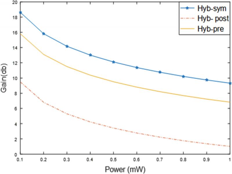
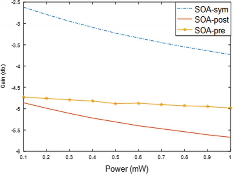
| 0.1 mW | 15.8 | 9.4 | 18.6 | −4.7 | −4.8 | −2.6 |
| 1 mW | 6.8 | 1 | 9.3 | −4.9 | −5.6 | −3.7 |
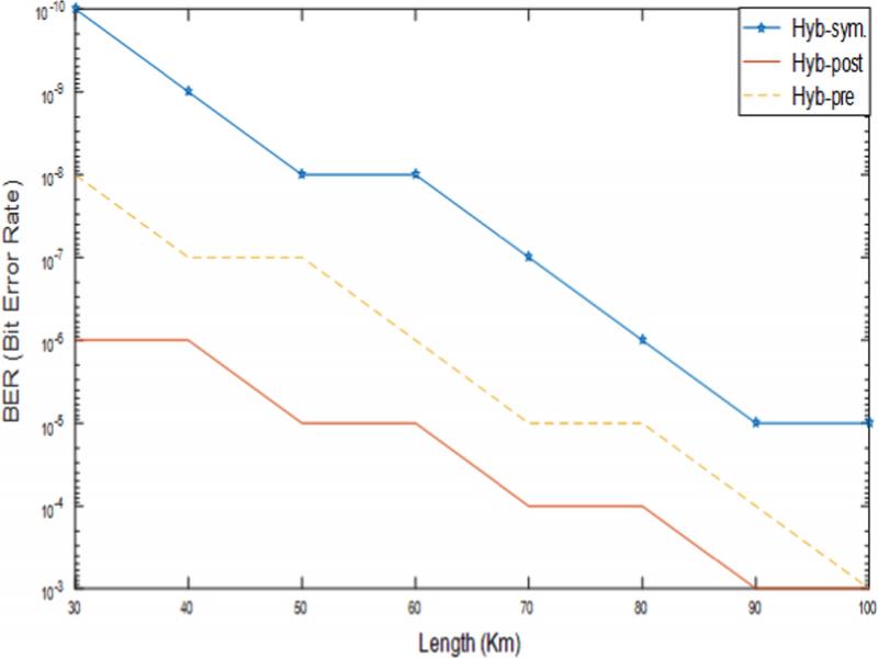
| Link range | |||
|---|---|---|---|
| Configuration | 50 km | 70 km | 100 km |
| Pre- | 10−7 | 10−5 | 10−3 |
| Post- | 10−5 | 10−4 | 10−2 |
| Symmetric- | 10−8 | 10−7 | 10−5 |