
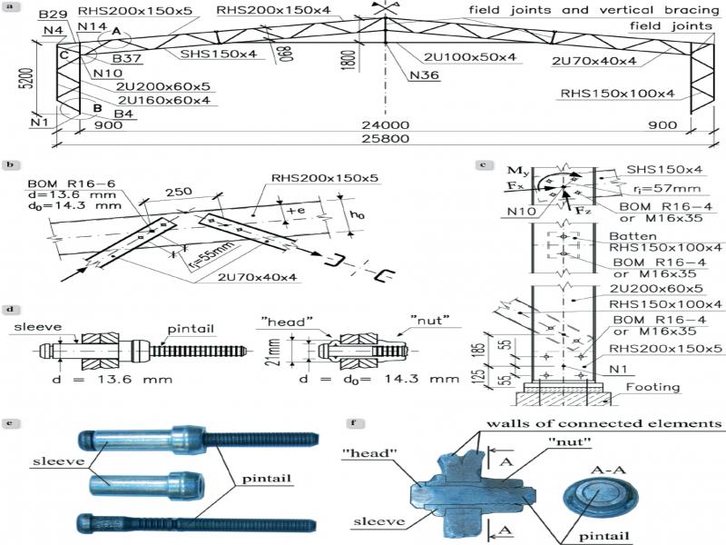
Figure 1.
Cold-formed steel frame with single-shear bolted connections [2]: a) geometry, b) detail “A” – structure of the truss joint, c) detail “B” and “C” – structure of the column, d) cross-section of the fastener before and after installation, e) view of the fastener before installation, f) cross-section of the fastener after installation
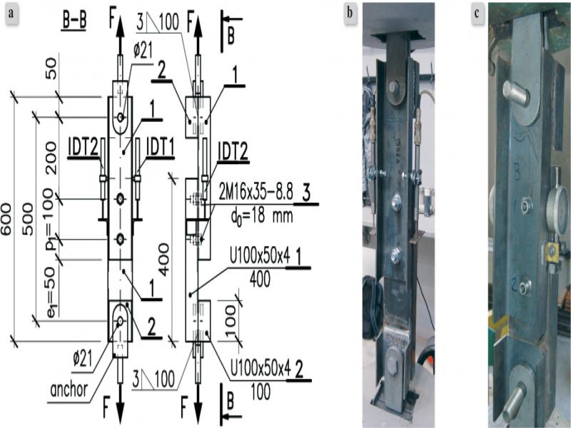
Figure 2.
Test specimen: a) construction and dimensions, b) specimen with M16 bolts, c) specimen with BOM R16-4 fasteners
Table 1.
Parameters of specimens with M16 bolts and BOM R16-4 fasteners
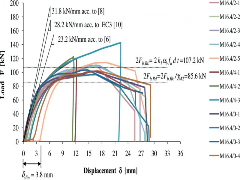
Figure 3.
The load-deformation characteristics of M16.4 specimens
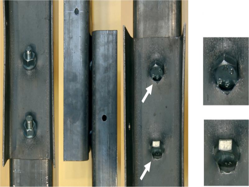
Figure 4.
Typical failure mode in specimens M16.4/2 with washers on nut side only
Table 2.
Test results for specimens M16.4/2 with washers under the nut only
| Specimen | Number of washers w | (Fmax) [kN] | δ (Fmax) [mm] | Bearing factor acc. to test Fmax/2fudt | Bearing factor acc. to EC3 [10] k 1 αb | Characteristic bearing resistance acc. to EC3 [10] 2Fb,Rk = 2k 1 αb fudt[kN] | Fmax /(2Fb,RK )]·100% |
|---|---|---|---|---|---|---|---|
| 1 | 2 | 3 | 4 | 5 | 6 | 7 | 8 |
| M16.4/2-1 | 2 | 108.2 | 15.4 | 2.33 | 2.31 | 107.2 | 101 |
| M16.4/2-2 | 107.9 | 17.1 | 2.33 | 100 | |||
| M16.4/2-3 | 110.2 | 16.7 | 2.37 | 103 | |||
| M16.4/2-4 | 109.6 | 16.3 | 2.36 | 102 | |||
| M16.4/2-5 | 114.1 | 19.0 | 2.46 | 106 |
Table 3.
Test results for specimens M16.4/4 with washers under the bolt head and nut
| Specimen | Number of washers w | (Fmax) [kN] | δ (Fmax) [mm] | Bearing factor acc. to test Fmax/2fudt | Bearing factor acc. to EC3 [10] k 1 αb | Characteristic bearing resistance acc. to EC3 [10] 2Fb,Rk = 2k 1 αb fudt[kN] | [Fmax /(2Fb,RK )]·100% |
|---|---|---|---|---|---|---|---|
| 1 | 2 | 3 | 4 | 5 | 6 | 7 | 8 |
| M16.4/4-1 | 4 | 120.01) | 12.0 | - | 2.31 | 107.2 | 112 |
| M16.4/4-2 | 122.41) | 11.5 | - | 114 | |||
| M16.4/4-3 | 142.52) | 9.1 | - | 133 |
Table 4.
Test results for specimens M16.4/0 without washers
| Specimen | Number of washers w | (Fmax) [kN] | δ (Fmax) [mm] | Bearing factor acc. to test Fmax/2fudt | Bearing factor acc. to EC3 [10] k 1 αb | Characteristic bearing resistance acc. to EC3 [10] 2Fb,Rk = 2k 1 αb fudt[kN] | Fmax /(2Fb,RK )]·100% |
|---|---|---|---|---|---|---|---|
| 1 | 2 | 3 | 4 | 5 | 6 | 7 | 8 |
| M16.4/0-1 | 0 | 101.6 | 15.8 | 2.19 | 2.31 | 107.2 | 95 |
| M16.4/0-2 | 96.7 | 16.6 | 2.08 | 90 | |||
| M16.4/0-3 | 103.3 | 14.3 | 2.23 | 96 | |||
| M16.4/0-4 | 102.1 | 16.8 | 2.20 | 95 | |||
| M16.4/0-5 | 101.6 | 16.8 | 2.19 | 95 |
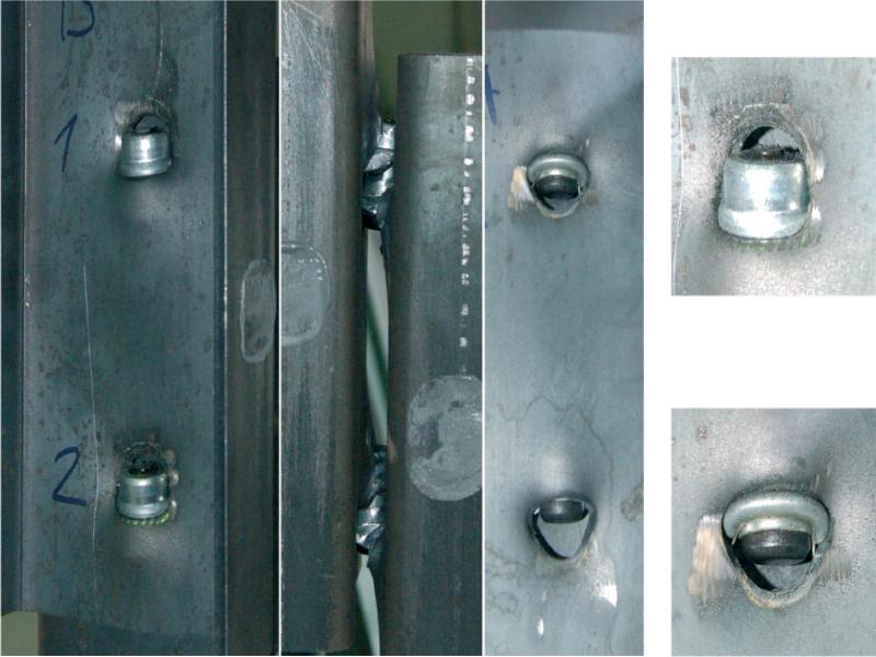
Figure 5.
Typical failure mode of BOM R-16 connections
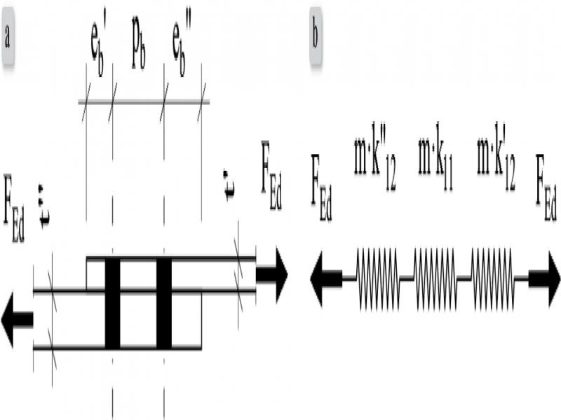
Figure 6.
Single-shear bolted connection: a) scheme and dimensions, b) mechanical model
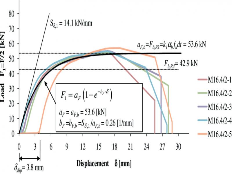
Figure 7.
Comparison of analytical and experimental F 1-δ characteristics for specimens M16.4/2
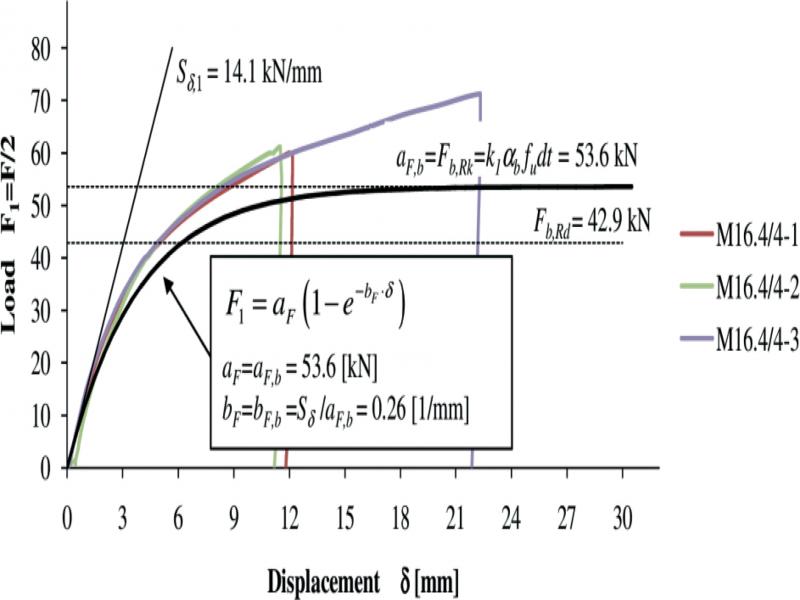
Figure 8.
Comparison of analytical and experimental F 1-δ characteristics for specimens M16.4/4
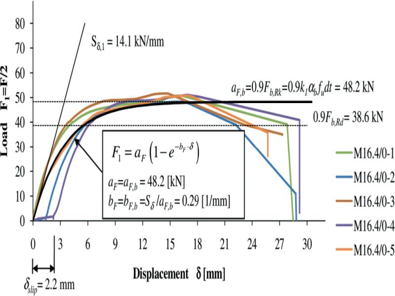
Figure 9.
Comparison of analytical and experimental F 1- characteristics for specimens M16.4/0
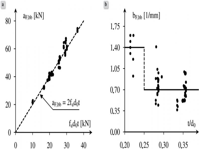
Figure 10.
Parameters of exponential function versus test results for connections with BOM fasteners: a) relation between a F,bb parameter and product of f u d 0 t, b) relation between b F,bb parameter and ratio of t/d 0
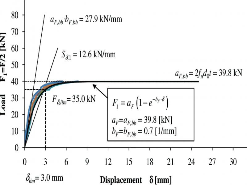
Figure 11.
Comparison of analytical and experimental F 1-δ characteristics for specimens BOM-S.4
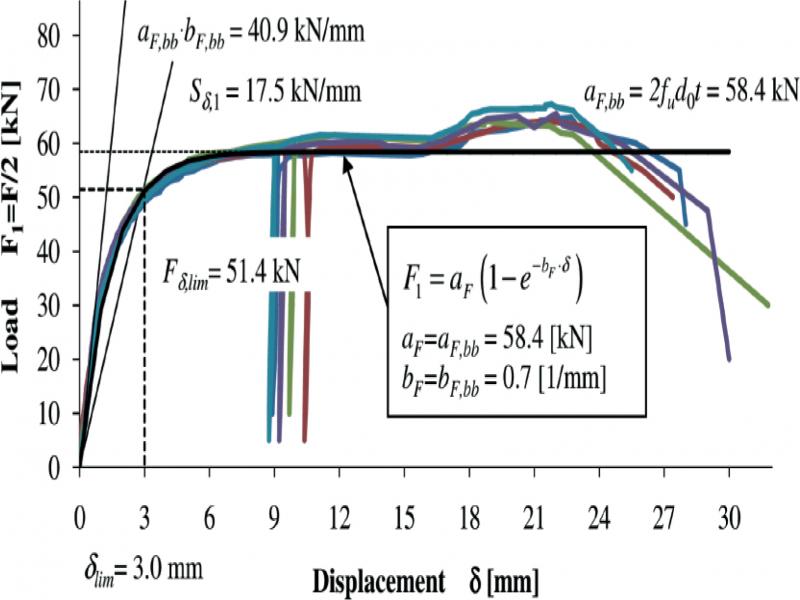
Figure 12.
Comparison of analytical and experimental F 1-δ characteristics for specimens BOM-KSW.4
Table 5.
Comparison of bearing factors for specimens with M16 bolts and blind fasteners BOM R16
| Bearing factor | Differences [%] | |||
|---|---|---|---|---|
| aF,b/fudt | aF,bb/fud0t | |||
| M16.4/2 w = 2 | M16.4/0 w = 0 | B0M-S.4 B0M-KSW.4 | [(l)/(3)-l]-100% | [(2)/(3)-l]·100% |
| 1 | 2 | 3 | 4 | 5 |
| 2.371) 2.312) | 2.183) | 2.004) | 18.5 15.5 | 9.0 |
1 1) test average (cf. Tab. 2), 2) k 1 b acc. to EC3, 3) test average (cf. Tab. 4), 4) see Fig. 10a
Table 6.
Initial stiffness of connections in tested specimens
| Specimen | Initial stiffness [kN/mm] |
|---|---|
| 1 | 2 |
| M16.4 | 14.11) |
| BOM-S.4 | 27.92) |
| BOM-KSW.4 | 40.92) |
1 1) acc. to eq. (2) for m = 1, 2) product of a F,bb and b F,bb
Table 7.
Nodal forces in frame for various types of joint model
| Bar/Node (cf. Fig. 1) | Force | Type of joint model | Differences | ||||
|---|---|---|---|---|---|---|---|
| Rigid | Semi-rigid | Nominally pinned | ([4]/[3]-l)·100% | ([5]/[3]-l)·100% | |||
| BOM R16 | BOM R16/M16 | ||||||
| 1 | 2 | 3 | 4 | 5 | 6 | 7 | 8 |
| B4/N1 | My [kNm] | 17.5 | 5.3 | 3.7 | 0.0 | -70 | -79 |
| Fx [kN] | 100.7 | 100.7 | 100.7 | 100.7 | 0 | 0 | |
| Fz [kN] | -46.0 | -31.1 | -26.8 | -37.7 | -32 | -42 | |
| B37/N10 | My [kNm] | -12.6 | -3.1 | -2.0 | 0.0 | -75 | -84 |
| Fx [kN] | 234.0 | 143.9 | 119.0 | 208.7 | -39 | -49 | |
| Fz [kN] | -66.8 | -49.2 | -47.3 | -57.4 | -26 | -29 | |
| B29/N14 | My [kNm] | -21.3 | -43.1 | -45.7 | -28.2 | 102 | 115 |
| Fx [kN] | -193.3 | -99.3 | -73.3 | -173.2 | -49 | -62 | |
| Fz [kN] | -48.9 | -53.5 | -53.9 | -33.9 | 9 | 10 | |