
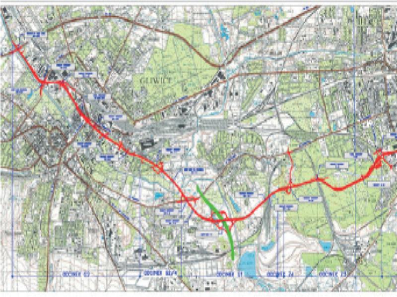
Figure 1.
The line of the sections G2, G1, Z4 and Z3 run
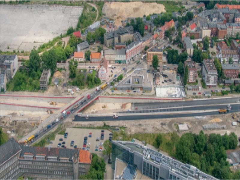
Figure 2.
A general view of the measurement area
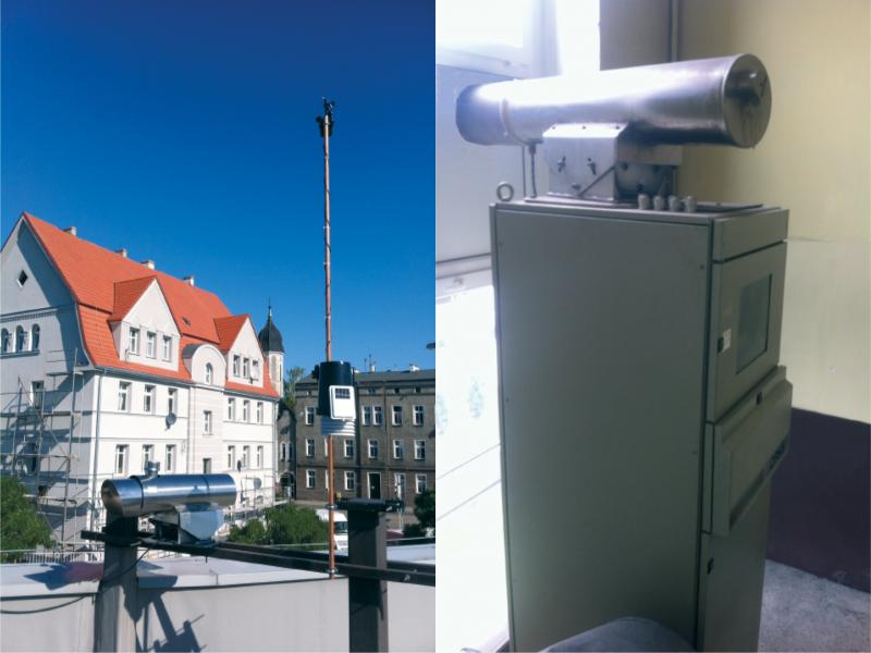
Figure 3.
A photo of the light beam transmitting and receiving device
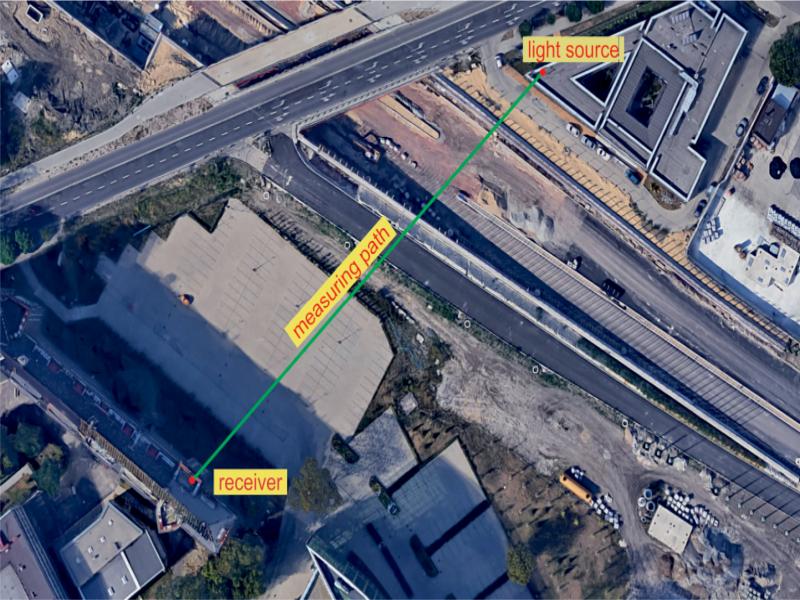
Figure 4.
Measurement area plan [Google maps]
Table 1.
Maximum and average values of NO2 concentrations in particular months, µg/m3
| month: | February | March | April | May | June | 5 months | |
|---|---|---|---|---|---|---|---|
| WIOŚ | maximum | 99 | 100 | 93 | 77 | 87 | 100 |
| OPSIS | maximum | 130 | 132 | 120 | 107 | 104 | 132 |
| WIOŚ | average | 34 | 29 | 19 | 20 | 17 | 24 |
| OPSIS | average | 89 | 87 | 83 | 83 | 81 | 85 |
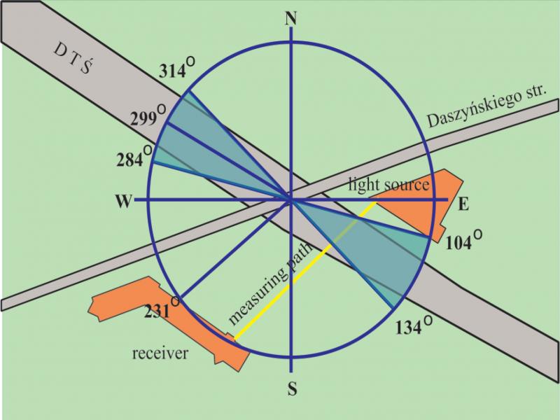
Figure 5.
The ranges of wind rose directions used for the construction works impact calculations
Table 2.
Average 5 months NOx concentrations measured by OPSIS system and WIOŚ station, the difference between them (local sources) and share of local sources in overall concentration
| OPSIS measurement | WIOŚ station (background) | Local sources | Share of local sources | |
|---|---|---|---|---|
| µg/m3 | µg/m3 | µg/m3 | % | |
| group 1 | 84 | 18 | 66 | 79 |
| group 2 | 85 | 24 | 61 | 72 |
| Difference: 7% |