
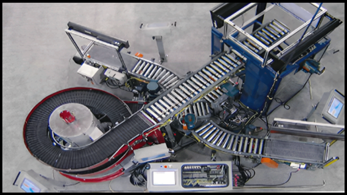
Figure 1
IDM Top View.

Figure 2
Human Machine Interface (HMI).
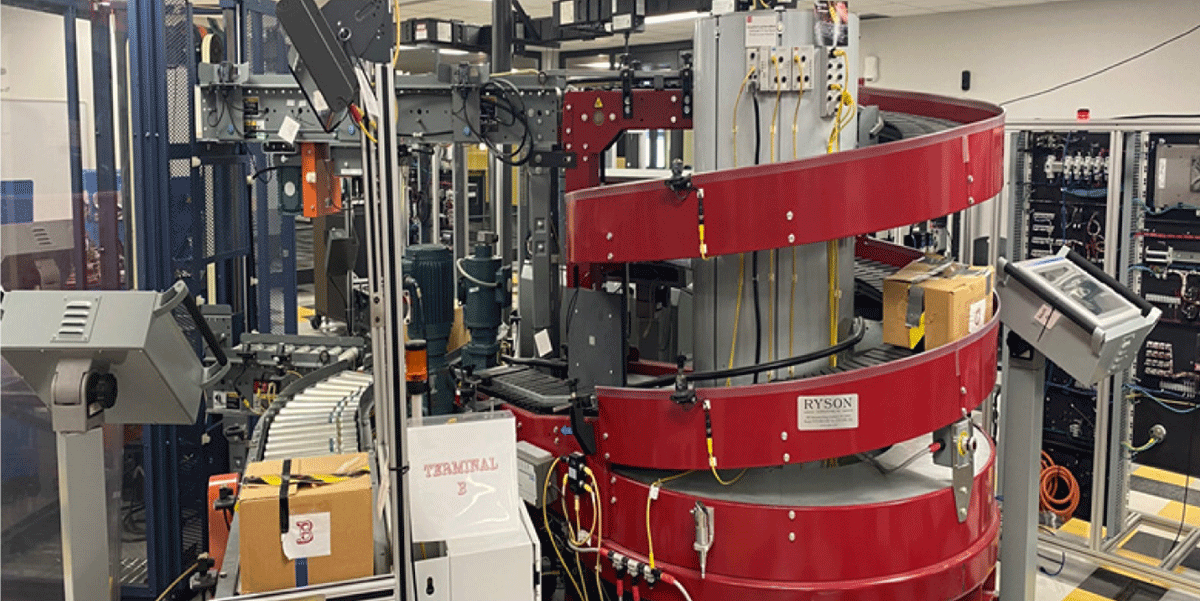
Figure 3
IDM with Multiple HMI.
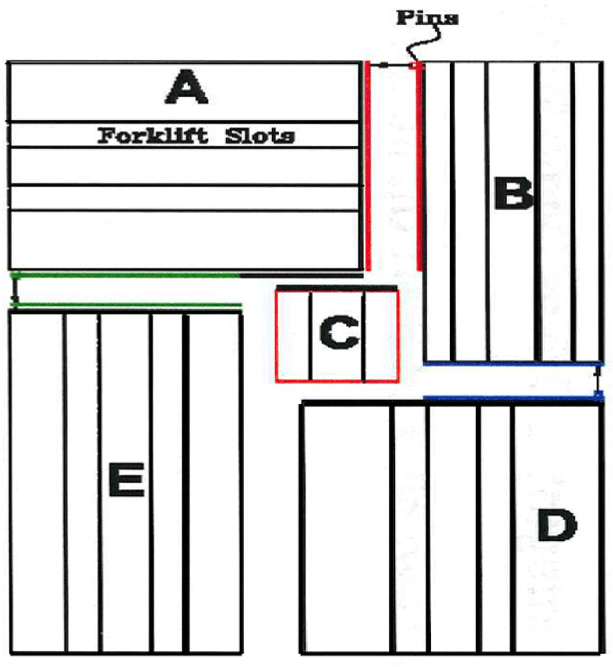
Figure 4
IDM layout.
A. Forklift; B. Safety; C. Turn Table; Small Conveyor, and Bridge (Upper Level); D. Spiral Conveyor; E. Step Logic Wing
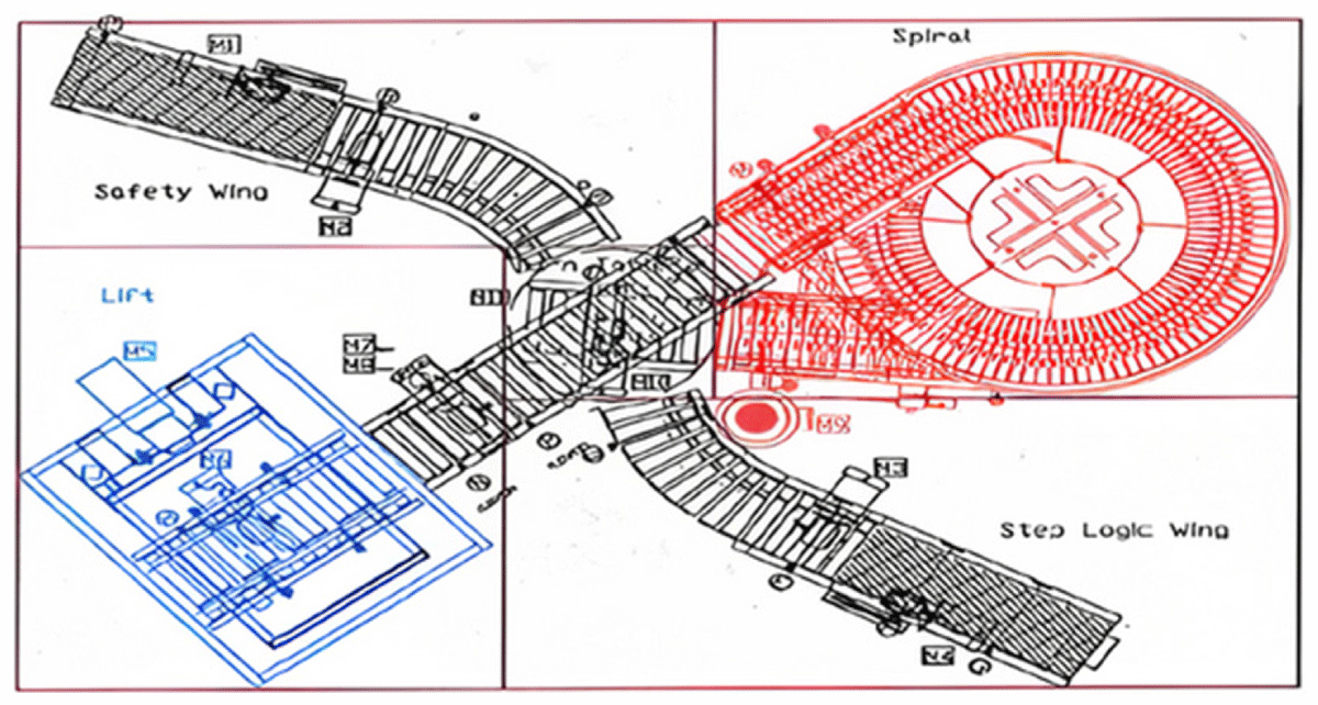
Figure 5
IDM layout Top View.
Table 1
Terminal A components.
| QUANTITY | DESCRIPTION |
|---|---|
| 2 | ½ HP Motor – These operate the lift and conveyor |
| 1 | Lift Platform |
| 1 | Conveyor – Belt-driven roach conveyor |
| 1 | Allen Bradley – Photoelectric Sensor |
| 1 | Enclosure (6 ft 8 in tall) Steel frame w/ safety glass on three sides |
| 2 | Message display screens (Currently unattached) |
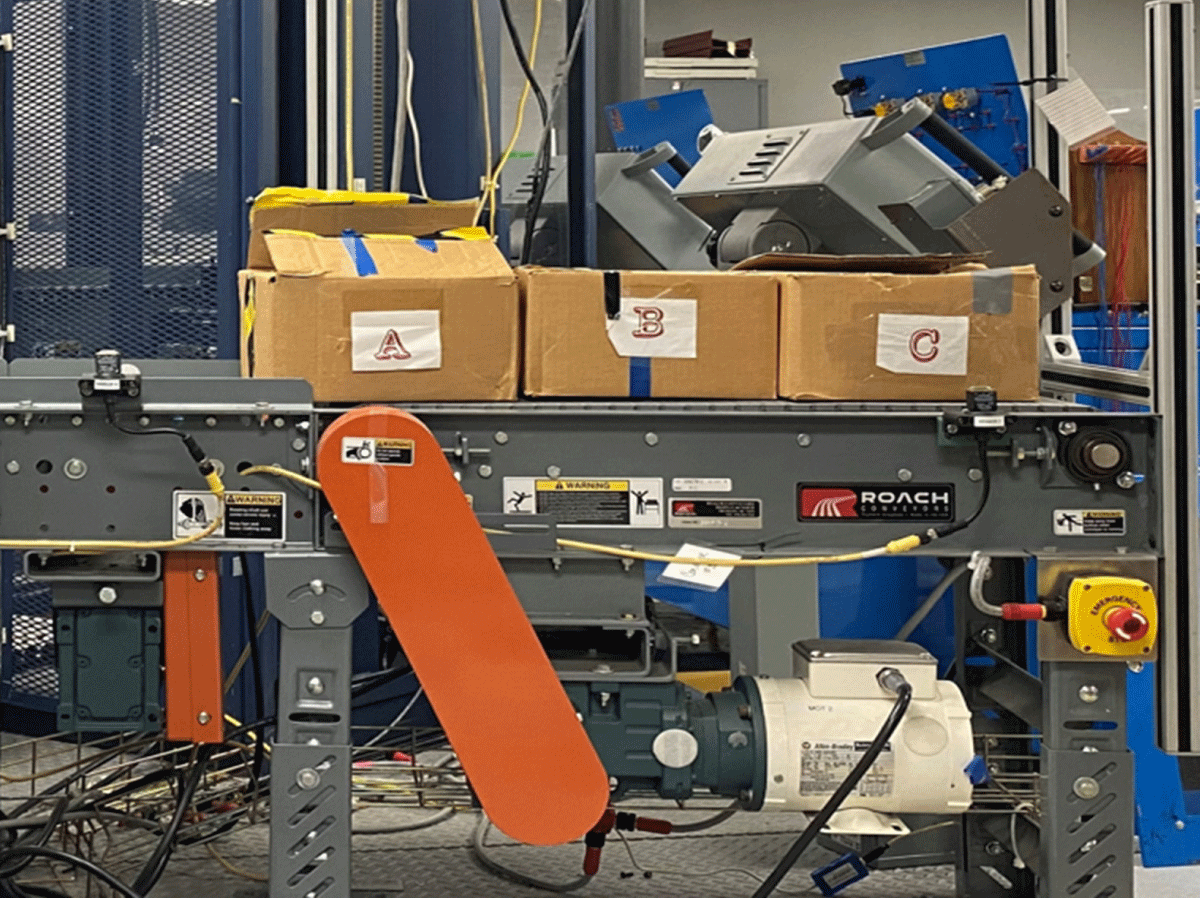
Figure 6
Starting Point.
Table 2
Terminal B components.
| QUANTITY | DESCRIPTION |
|---|---|
| 2 | ½ HP Motor- These operate the lift and conveyor |
| 1 | Lift Platform |
| 1 | Conveyor – Belt driven roach conveyor |
| 1 | Allen Bradley – Photoelectric Sensor |
| 1 | Enclosure (6 ft 8 in tall) Steel frame w/ safety glass on three sides |
| 2 | Message display screens (Currently unattached) |
Table 3
Terminal C components.
| QUANTITY | DESCRIPTION |
|---|---|
| 4 | ½ HP Motor – These operate the lift and conveyor 2-Turn Table 1-Bridge 1-Small Conveyor |
| 3 | Roach Conveyors 1-Turn Table 1-Bridge 1-Small Conveyor |
| 3 | Sensors – Smart Zone Sensor located on the conveyor and bridge |
| 5 | Allen Bradley – Photoelectric Sensor 3-Bridge 1-Turn Table 1-Small Conveyor |
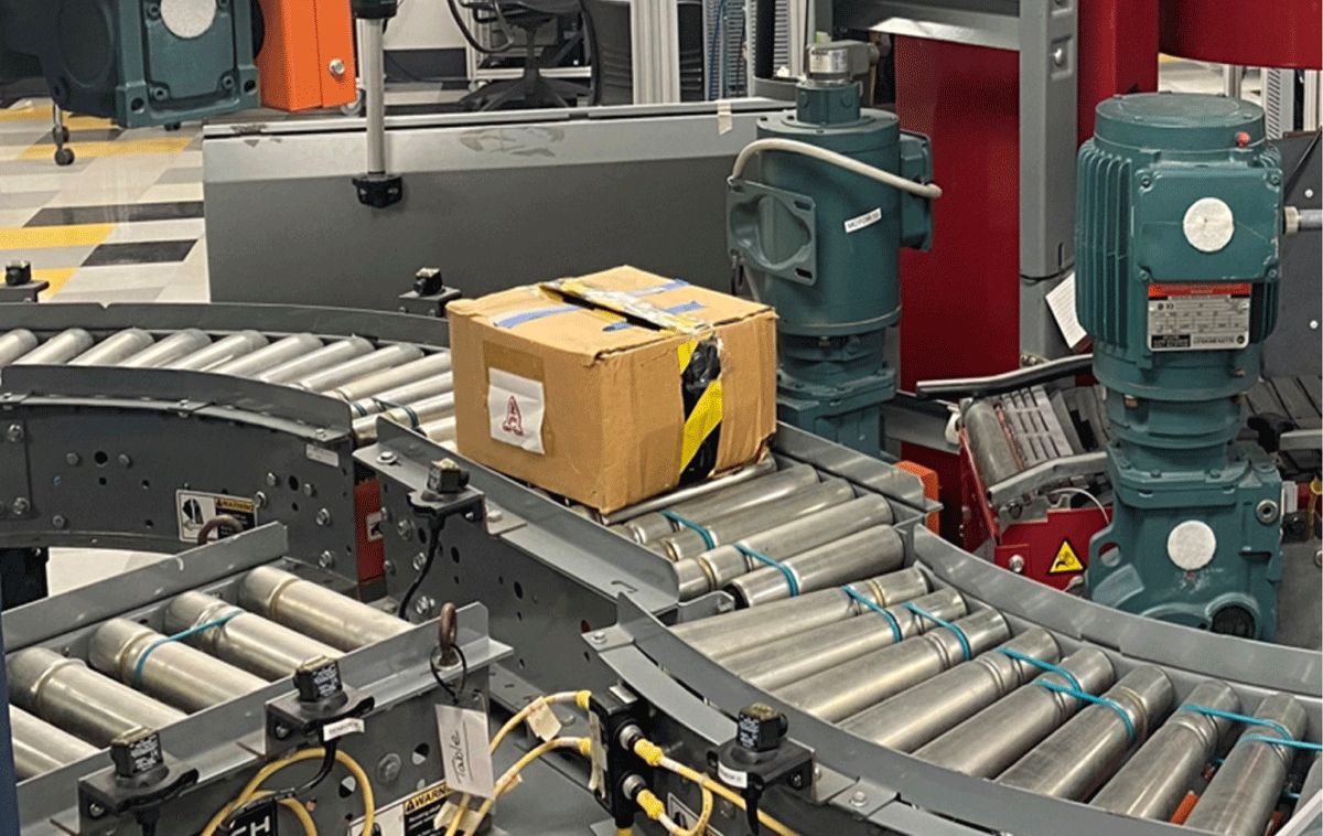
Figure 7
Turning Table.
Table 4
Terminal D components.
| QUANTITY | DESCRIPTION |
|---|---|
| 1 | ½ HP Motor – For the Conveyor |
| 1 | Ryson Spiral Conveyor – Runs on slates |
| 1 | Red safety light |
| 2 | Allen Bradley – Photoelectric Sensor |
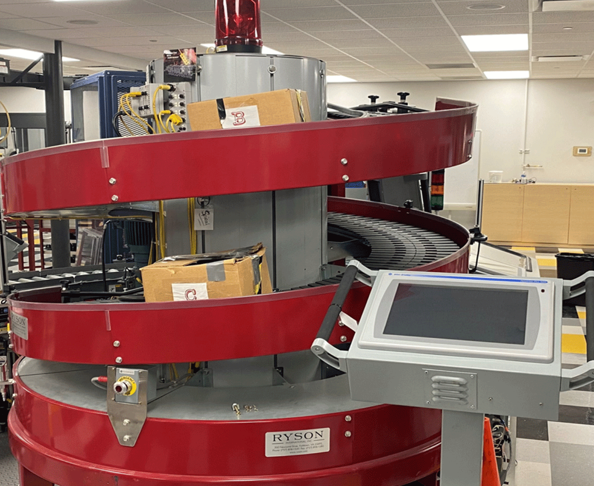
Figure 8
The Spiral Conveyor.
Table 5
Terminal E components.
| QUANTITY | DESCRIPTION |
|---|---|
| 2 | ½ HP Motor – For the Conveyor |
| 1 | Message Screen (Not Operational) |
| 2 | Roach Conveyor 1-Straight with plastic belt 1-Curved roller belt |
| 2 | Allen Bradley – Photoelectric Sensor |
| 1 | Yellow light bar |
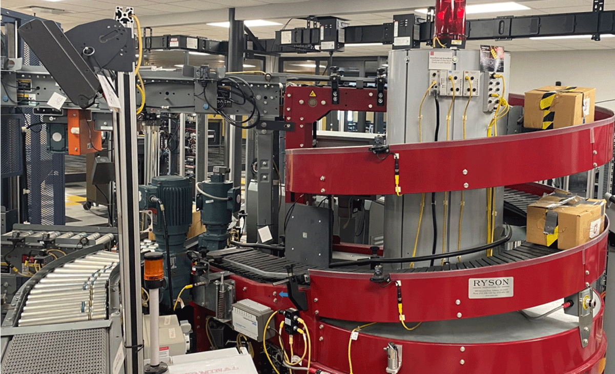
Figure 9
Terminal E – Step Logic Wing.
Table 6
PLC Controller cabinet components.
| CONTROL TERMINAL HARDWARE COMPONENTS | ||
|---|---|---|
| ControlLogix PLC | Expandable I/O | Optional Comm. Cards |
| Optional Analog I/O | Motion Control | Powerflex 4 |
| Powerflex 40 | Powerflex 70 | ArmorStart (Remote VFD) |
| Sensors | Photo Eyes | Encoders |
| Display indicators | E-Stop | HMI Panel |
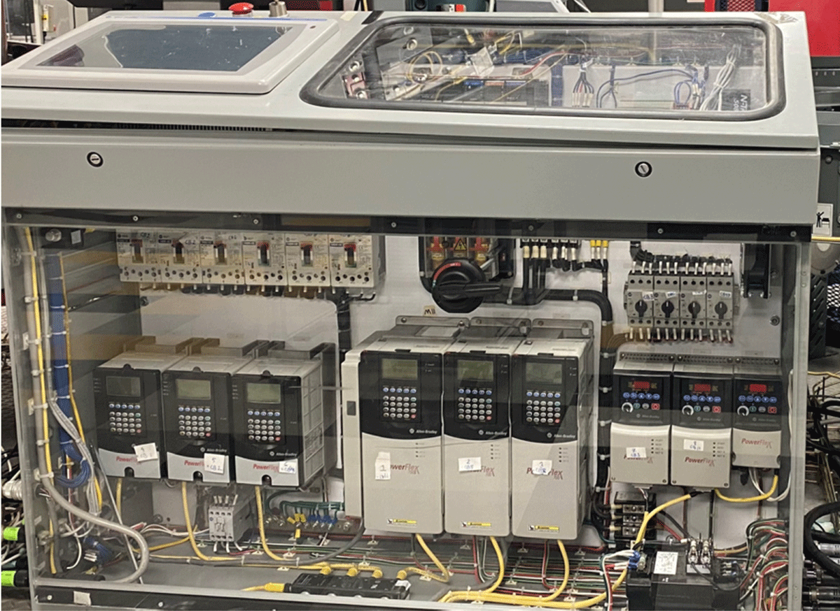
Figure 10
PLC Controller Cabinet.