
Introduction
The advantages of university-industry partnerships are many. The strength of a university program depends on staying relevant to technology and current market trends, not only regionally but globally (Jones, 2015). Having strong industry partnerships allows students and university stakeholders to learn about current and future technology. Furthermore, this partnership between the university and the technology industry provides a pipeline for internship and co-op opportunities for the students that participated in real applications projects. The partnership between Rockwell and Purdue University Northwest (PNW) exemplifies that unity (Sjostedt, 2022).
Utilizing software and technology from an industry leader allows our students and unemployed individuals who are seeking to up-skill through workforce training at the Commercialization and Manufacturing Excellence Center (CMEC) to learn about some of the newest equipment. Additionally, industry partnerships allow our students to take part in industry-led conferences, seminars, and training (Prigge, 2005). Finally, by having a strong network of industry partnerships, it is the hope that upon graduation students involved in the Advanced Manufacturing Programs at PNW will have a better understanding of technologies offered within technical and industry settings (Gregory, 2000; Prigge, 2017).
PNW and Rockwell Automation is currently engaged in an ongoing effort to foster the availability of up-to-date training equipment and locations for skill-up grading in advanced manufacturing as it concerns programmable logic controllers (PLCs). This is not an exclusive partnership as PNW is part of Rockwell’s Educator Consortium (Rockwell, 2020). This global consortium is made up of universities and technical training centers from around the world who meet annually at Rockwell’s yearly training convention.
This partnership has enabled PNW to receive equipment, software, and supplemental curriculum from Rockwell to align with today’s industry needs and future upcoming developments. With the partnership created by the Educator Consortium and PNW’s presence at Rockwell Headquarters, an opportunity presented itself through casual conversation between PNW College of Technology faculty and Rockwell Executives: a tradeshow exhibit was available. Rockwell created an integrated, automated conveyance system that represented their company’s abilities. This unit was earmarked to be decommissioned by Rockwell but instead was transferred to PNW. Part of the agreement was that PNW oversaw and assisted in the disassembling, crating, and logistics of moving the unit from Rockwell’s R&D department in Milwaukee, WI, to the new PNW CMEC, (CMEC, 2022). PNW staff members and several students worked in Milwaukee to deconstruct the equipment and then, several weeks later, were supervised by PNW faculty to reassemble the unit to full functionality. The unit is currently being used for PNW degree-seeking students, industry training partners, and qualified recipients of unemployment benefits for a new career and up-skill training as shown in Figure 1.
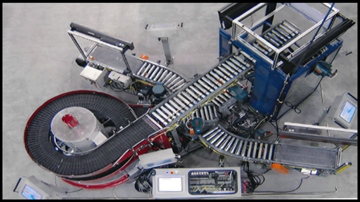
Figure 1
IDM Top View.
This paper is broken up into four sections: Introduction, Human Machine Interface (HMI), Terminal Position, and Conclusions. The HMI and Terminal Position sections explain, in detail, the components of the Integrated Drive Machine (IDM) and their uses for students.
Human Machine Interface (HMI)
The IDM comes with five Panel-View Plus 1500 screens, four of which are on pedestal stands located on the four sides of the IDM. The other screen is located by the PLC, as seen on the far-left side of Figure 2 as well as in Figure 3. It also has one Versa-View 1700P screen on a stand located next to the PLC as shown in Figures 2 and 3.
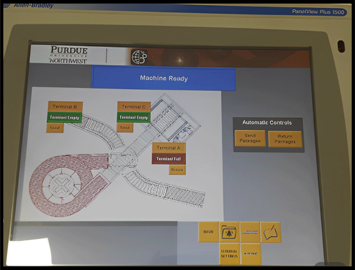
Figure 2
Human Machine Interface (HMI).
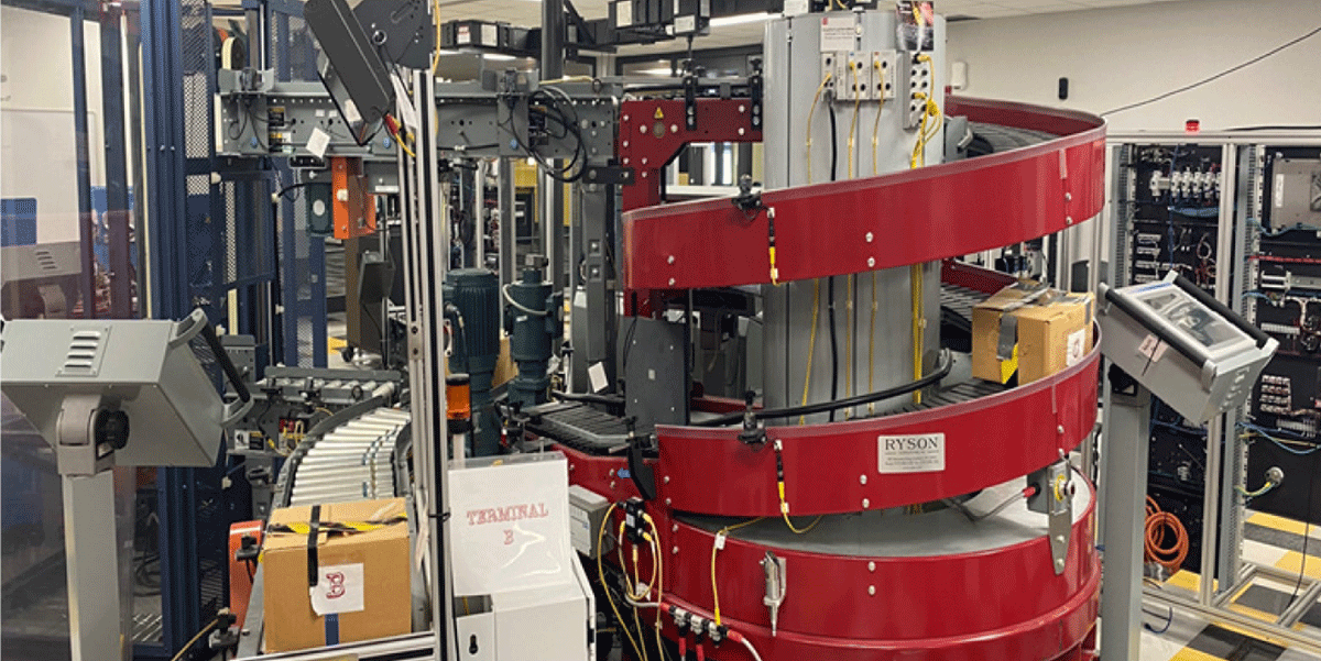
Figure 3
IDM with Multiple HMI.
These HMI screens allow the user to operate the IDM’s components from each station. They can be set at any distance away from the components while providing accessibility and feedback.
When the IDM is in operation, the HMI stations allow the user to see the current status of the items that are being transported throughout the machine. For example, if there is an item located in terminal A, the HMI will display the following readout as seen in Figure 4. From this point, the user can designate which terminal the item should be sent to. This is done via the touch screen by simply pressing one of the three terminals’ ‘send’ buttons. Once the item has been sent to the designated terminal and is successfully received, the user will be notified of a change in terminal status. The box under the terminal name will change from green to red and state whether it is full or empty.
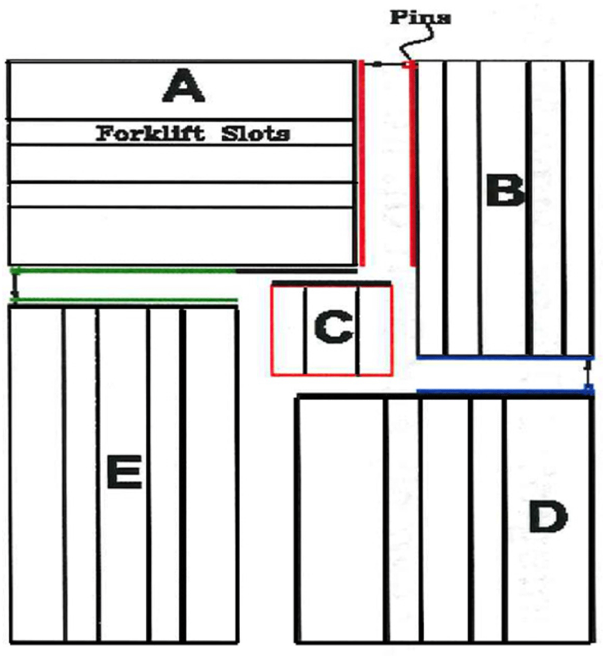
Figure 4
IDM layout.
A. Forklift; B. Safety; C. Turn Table; Small Conveyor, and Bridge (Upper Level); D. Spiral Conveyor; E. Step Logic Wing
Upon start-up of the IDM, the user is greeted with a welcome message (Figure 6) at any of the HMI stations. The screen will display a customized message welcoming the user or company that is viewing a demonstration. This feature provides a sense of personalization to the presentation. Other options located on the screen are information about Rockwell Automation as well as ARPAC. Help captioning is located just under these two companies informing the user that more information is provided. From this screen, five other options can be selected via buttons on the bottom right side of the HMI. These options include ‘terminal settings,’ ‘alarm history,’ ‘ARPAC info,’ ‘Rockwell automation info,’ and ‘Recipe Guide,’ which would provide full machine customization for shipping methods depending on the items.
Terminal Composition
The IDM can be divided into five components, as shown in Figure 4. These terminals as shown below are composed of the following.
Each component section of the IDM will now be briefly discussed. A parts list for each section will also be provided beside each section. The IDM layout top view is shown in Figure 5.
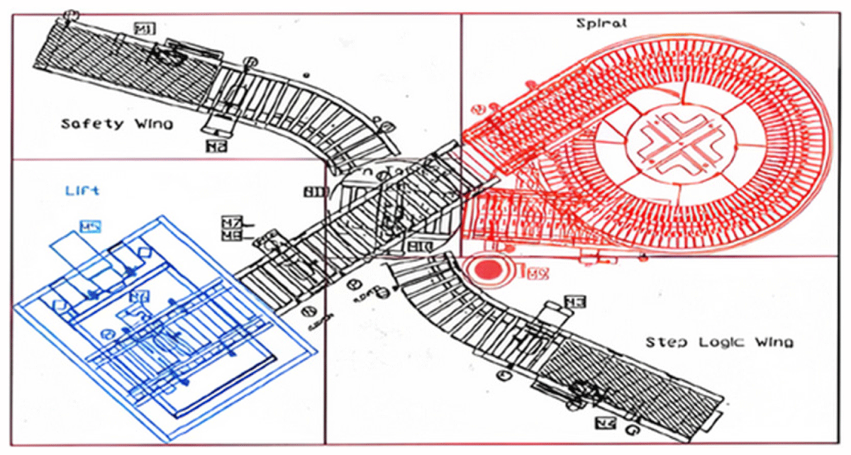
Figure 5
IDM layout Top View.
Terminal “A” – Forklift
The forklift is used to take an object such as a parcel from the upper level (Bridge conveyor, terminal C) to the lower level (Small Conveyor, terminal C) and vice versa. Unfortunately, this forklift is currently not operational and will be replaced with a robotic arm in the future. The main components of this section are listed in Table 1.
Table 1
Terminal A components.
| QUANTITY | DESCRIPTION |
|---|---|
| 2 | ½ HP Motor – These operate the lift and conveyor |
| 1 | Lift Platform |
| 1 | Conveyor – Belt-driven roach conveyor |
| 1 | Allen Bradley – Photoelectric Sensor |
| 1 | Enclosure (6 ft 8 in tall) Steel frame w/ safety glass on three sides |
| 2 | Message display screens (Currently unattached) |
Terminal B – Safety Wing – ‘Staring Point’
The safety wing is used for starting the processing because it has a safety switch. From here, the user places the item on the conveyor belt with the barcode image facing the photoelectric sensor. The HMI screen shows that the respected terminal is full and is ready to be sent. Also, this area can be used as the returning station as shown in Figure 6. In addition, the main components of this section are listed in Table 2.
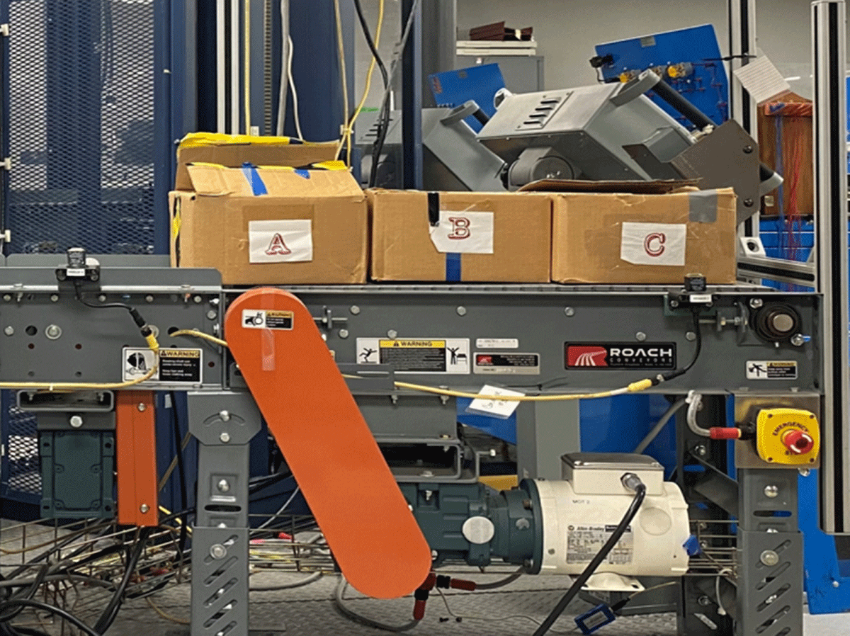
Figure 6
Starting Point.
Table 2
Terminal B components.
| QUANTITY | DESCRIPTION |
|---|---|
| 2 | ½ HP Motor- These operate the lift and conveyor |
| 1 | Lift Platform |
| 1 | Conveyor – Belt driven roach conveyor |
| 1 | Allen Bradley – Photoelectric Sensor |
| 1 | Enclosure (6 ft 8 in tall) Steel frame w/ safety glass on three sides |
| 2 | Message display screens (Currently unattached) |
Terminal C – Turn Table, Small Conveyor, and Bridge (Top Level)
Although it is not a specific terminal, the turn table is used for directing the object from one direction to another. It is driven by two motors: one for moving a table from one location to another and the other to rotate the roller conveyor. There is also a small conveyor that connects to section A and a bridge above the turn table that connects the spiral in section D to the forklift in section A. The terminal C is shown in Figure 7. Also, the main components of this section are listed in Table 3.
Table 3
Terminal C components.
| QUANTITY | DESCRIPTION |
|---|---|
| 4 | ½ HP Motor – These operate the lift and conveyor 2-Turn Table 1-Bridge 1-Small Conveyor |
| 3 | Roach Conveyors 1-Turn Table 1-Bridge 1-Small Conveyor |
| 3 | Sensors – Smart Zone Sensor located on the conveyor and bridge |
| 5 | Allen Bradley – Photoelectric Sensor 3-Bridge 1-Turn Table 1-Small Conveyor |
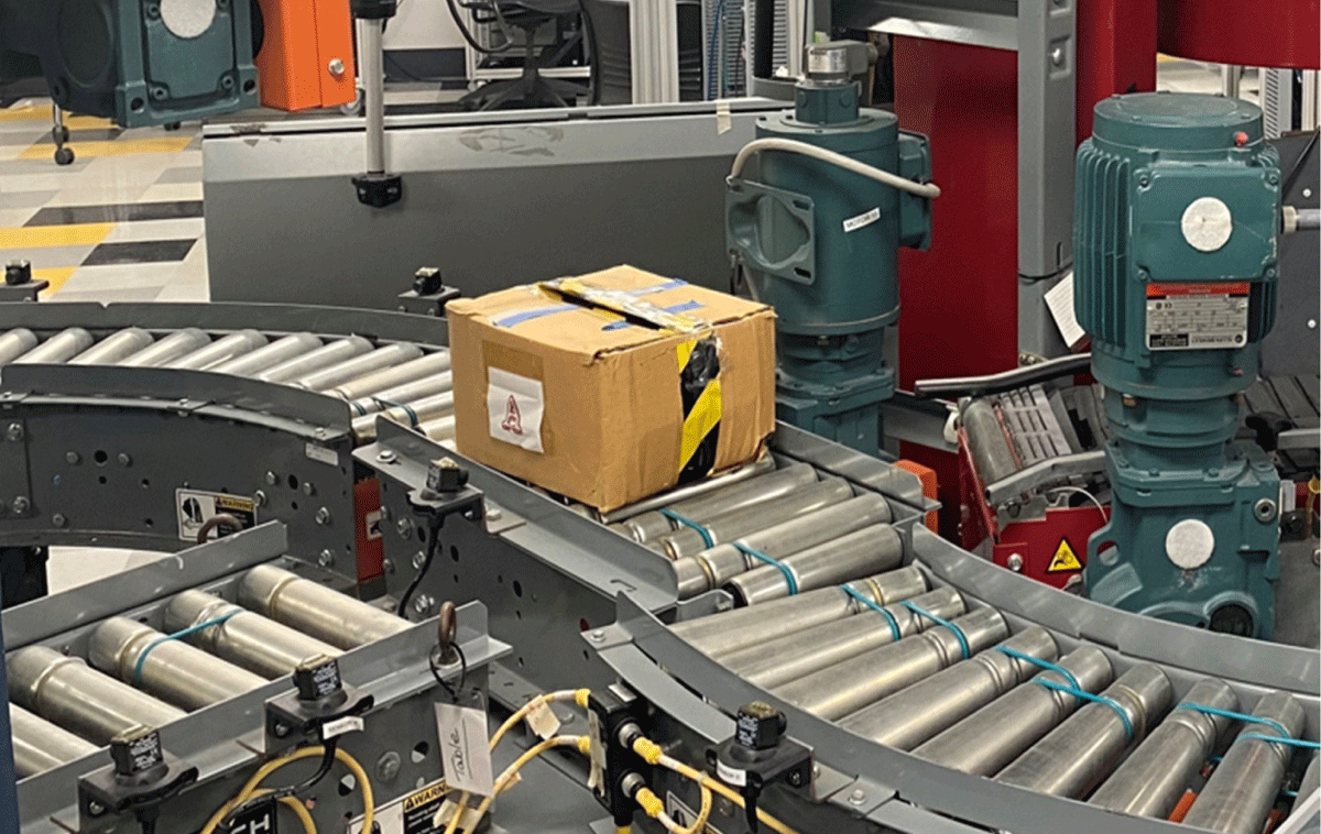
Figure 7
Turning Table.
Below are the main components used in this section, listed in Table 3.
Terminal D – Spiral Conveyer
The Spiral Conveyor is a new concept in vertical conveying, designed to conserve valuable floor space. The conveying surface is comprised of a series of chains and slats supported by a low-friction guide system. The spiral can convey loads up or down in a continuous operation. The speed of the spiral conveyor is synchronized with the conveyors feeding in and out of the spiral. A Variable Frequency Drive (VFD) is used for moving the conveyer while maintaining the proper operation of the spiral. The terminal D is shown in Figure 8. The main components of this section are listed in Table 4.
Table 4
Terminal D components.
| QUANTITY | DESCRIPTION |
|---|---|
| 1 | ½ HP Motor – For the Conveyor |
| 1 | Ryson Spiral Conveyor – Runs on slates |
| 1 | Red safety light |
| 2 | Allen Bradley – Photoelectric Sensor |
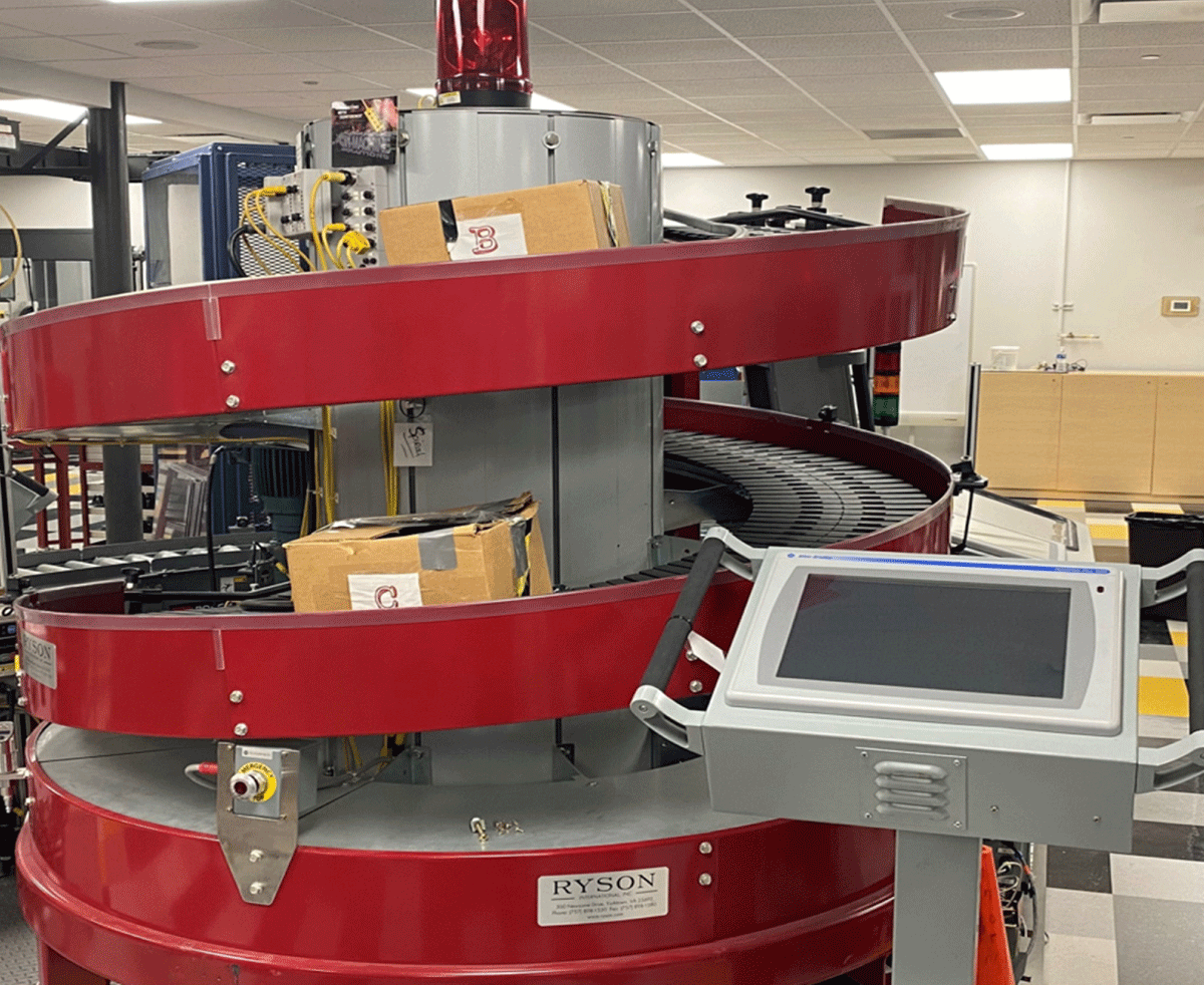
Figure 8
The Spiral Conveyor.
Terminal E – Step Logic Wing
The Step Logic Wing is similar to the Safety Wing. It is used as a temporary holding area for items. This can also be used as a starting point. Upon receiving the item, a message would be displayed on the overhead message screen. This notifies the user of any specific instructions or requirements about the item. The terminal E is shown in Figure 9; also, the main components of this section are listed in Table 5.
Table 5
Terminal E components.
| QUANTITY | DESCRIPTION |
|---|---|
| 2 | ½ HP Motor – For the Conveyor |
| 1 | Message Screen (Not Operational) |
| 2 | Roach Conveyor 1-Straight with plastic belt 1-Curved roller belt |
| 2 | Allen Bradley – Photoelectric Sensor |
| 1 | Yellow light bar |
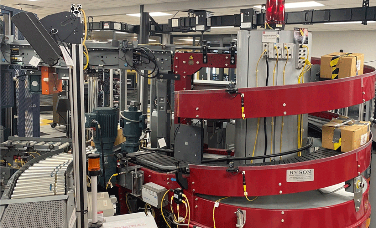
Figure 9
Terminal E – Step Logic Wing.
Programmable Logic Controller
Controlling the entire IDM is a Control Logix PLC that is equipped with an expandable I/O, as well as optional communication methods via different card slots (Ethernet, DeviceNet, etc.). The hardware for this setup was graciously donated by Rockwell for the benefit and improvement of the students in the Engineering and Mechatronics program. The PLC controllers are shown in Figure 10 and the main components of the controller are listed in Table 6.
Table 6
PLC Controller cabinet components.
| CONTROL TERMINAL HARDWARE COMPONENTS | ||
|---|---|---|
| ControlLogix PLC | Expandable I/O | Optional Comm. Cards |
| Optional Analog I/O | Motion Control | Powerflex 4 |
| Powerflex 40 | Powerflex 70 | ArmorStart (Remote VFD) |
| Sensors | Photo Eyes | Encoders |
| Display indicators | E-Stop | HMI Panel |
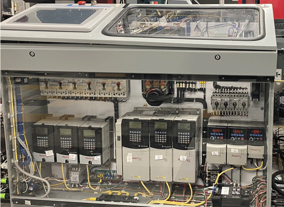
Figure 10
PLC Controller Cabinet.
Impacts
The disassembling and reassembling process of the IDM was a very hands-on and intuitive experience for the students involved. Not only do the students get to walk away with real-life experience with technology that is used in industries today, but they also paved the way for other students to interact with those same technologies. The reassembled IDM at PNW’s CMEC facility allows current and future students to interact with, study, and troubleshoot a real automation process. This process can be built upon and modified at the instructor’s discretion and is not limited by the influence of any one company. Although the IDM was graciously donated by Rockwell Automation, the students can use the system to learn how to integrate components from other manufacturers to gain a broader understanding of industrial processes. Mechatronics students specifically will benefit from this sort of learning tool because it applies directly towards the degree: a combination of both hands-on mechanical experience as well as electrical. The system can be reprogrammed and reworked in any way, with the only limitation being the student’s creativity.
Conclusions
The IDM is an excellent addition to the mechatronics program at PNW. Although this exact system cannot be available to all schools, it serves as a template for other schools to follow. A large-scale automation process such as this is integral to teaching students how mechanics and electronics come together in an industrial environment. Through a very engaging and hands-on method, the IDM provides something that a normal classroom cannot: a look into the student’s future. This system is helping programs to have a real-world experience with real machine size that could see on the floor upon their graduation. Finally, this type of machine helps students that could not get experience and a chance to any internships or co-op opportunities to involve and work with a real machine. Future papers will collect data on the overall efficacy of equipment implemented via industry partnerships.
Acknowledgement
The author would like to thank Rockwell automation and the UPP program team. Also, Mr. Michael Cook, Rockwell Automation Incorporated, Global Director, University Partnership Program. Director, University Partnership Program for Rockwell Automation.
Competing Interests
The author has no competing interests to declare.