
Structurally, a concrete-filled steel tubular (CFST) element, in cross-section, consists of a steel shell tube filled with concrete which is further reinforced with high-strength conventional or prestressed reinforcement bars. The concrete inside the steel tube serves several purposes: it absorbs significant transverse forces, ensures the joint operation of the steel tube with both conventional and prestressed reinforcement, and increases the longitudinal stability of the CFST element during reinforcement tensioning. At the same time, the concrete acts as a protective barrier against corrosion for the high-strength longitudinal reinforcement bars and the inner surface of the steel tube in CFST elements. The load-bearing capacity of a tensioned CFST element is determined by the combined strength of the steel tube, the concrete, and the high-strength steel of the reinforcement bars.
The proposed calculation method, aimed at enhancing the load-bearing capacity of tensioned CFST elements compared to existing standard methods, takes into account the plastic properties of the strain-hardened mild steel tube. It uses the ultimate strength of the steel tube at its limit state and the design resistance of the high-strength reinforcement bars. The calculation models and main conditions should accurately reflect the actual behavior of tensioned CFST structures, and the calculation methodology should be implemented using computer-based methods (ECM).
The efficiency of tensioned CFST elements becomes particularly evident when the independent load-bearing capacity of the high-strength reinforcement bars exceeds that of the steel tube – the greater this difference, the more reliable the structure performs.
CFST structures must meet the requirements of modern regulatory documents, considering the rational profiles of steel tubes, welded box profiles, concrete, and high-strength reinforcement bars.
The availability of standard sizes of steel pipes of different profiles, cross-sections and diameters and high-strength reinforcing steels of different classes, diameters and strength provide the basis for the calculation and design of tensioned reinforced concrete pipe elements of a given load-bearing capacity.
The bearing capacity of a stretched element in the limit state is determined by the formula found in modern regulatory documents, namely:
N_y^m A_s^{mp},R_y^{mp} A_s^{cm},R_y^{cm} kb – the coefficient of influence on the tensile strength of concrete in the pipe casing, which in the limit state is equal to 1.
Concrete is excluded from the work, since the cracks are completely opened over the entire cross-section.
The bearing capacity of tubular reinforced concrete elements is proposed to be determined by improved formula:
N_u^m A_s^{mp},R_u^{mp}
According to formula (2), when compared to formula (1), for tensioned tubular reinforced concrete elements reinforced with steels of different classes beyond the plastic limit, an overall increase in bearing capacity is achieved. This is based on the plastic self-hardening property of mild steel pipe and assuming the ultimate strength characteristic for mild steel pipe and the conditional design strength of steel for high-strength steel rebar.
The increase in the bearing capacity of reinforced concrete pipe elements in the limiting stage is determined as the difference between the bearing capacities according to the improved formula (2) and formula (1) of modern regulatory documents:
At the same time, it is advisable to display the part of the cross-sectional area of the steel pipe of the reinforced concrete element that is perceived by the force of increasing the bearing capacity of the pipe:
The economic effect in percentage will be determined by the ratio of this part of the area to the total area of the steel pipe, namely:
As for the increase in the bearing capacity of a reinforced concrete tubular element relative to the standard value, it is determined in percentage as:
For a more visual idea of economic efficiency, it is advisable to determine the mass of the steel pipe savings per one linear meter of the reinforced concrete pipe element, i.e.
G – the mass of steel savings per linear meter,
γsteel – density of steel in kg per 1 m3.
We will demonstrate the determination of the bearing capacity and economic efficiency of a reinforced concrete tubular element using an example.
Initial data: Steel pipe, outer diameter 114 mm, inner diameter 108 mm, thickness 3.0 mm,
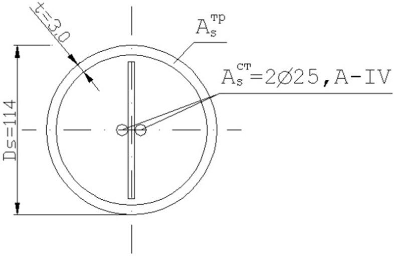
Cross-section of a tubular reinforced concrete element (own research)
Based on the above analytical and numerical calculations, a numerical model for calculating such structures on a computer has been developed. The program has been compiled and implemented in the Turbo environment. Pascal 7.0 (Complete Guide to Turbo Pascal 7.0, 1983; Lancaster, 1985).
The program consists of two large modules trubo_beton_1 and trubo_beton_2. The first module contains procedures for inputting and outputting input information: geometric dimensions of elements (cross-sectional areas of reinforcing bars and pipes, concrete), their geometric locations relative to the center of the section, physical characteristics of materials (modules of elasticity), their control points from real deformation diagrams of materials, viewing intermediate calculation results, forming longitudinal and transverse stress plots and deformation graphs. The second module contains calculation procedures, constructing real deformation diagrams of concrete and reinforcing steel, calculating stress and deformation, and performing iterative calculation processes.
In works (Barabash, 1977; Klymenko & Shmyh, 1994; Onyskiv et al., 2001), the calculation method is considered, and a numerical model is developed for reinforced concrete structures operating in bending. The decisive factor in the failure of such structures was the loss of strength of compressed elementary layers at the point of application of external load.
In our case, the loss of bearing capacity occurs due to the destruction of elementary layers from tension, that is, the bearing capacity is determined entirely by the tension section of the material σ diagram ɛ.
Concrete σ-ɛ diagram was described using a quadratic dependence according to the proposals of the EKB-FIP with the clarification of the coefficients proposed in the works (Barabash, 1988a; Barabash, 1988b). For the stretched section of the concrete diagram, the following relationship was used:
\eta = {{{\varepsilon _{bi}}} \over {{\varepsilon _{bu}}}} ɛbi, ɛbu – tensile deformations of concrete, which correspond to the highest tensile stresses Rbt,
k0 – coefficient that takes into account plastic deformations in concrete.
In the diagram σ-ɛ for reinforcing steel, a rectilinear dependence was assumed in the sections up to the elastic limit, and the curvilinear sections were described using the quadratic dependence of the EKB-FIP.
The calculation model is based on a discrete representation of the rod. It is assumed that a tubular reinforced concrete rod operating in central tension consists of individual sections along the axis, and of layers of concrete k, reinforcing steel n layers, and metal pipe m layers along the height (Fig. 2). The circular cross-section of the specimen is conditionally divided into rectangular quadrangles of equal area. The total value of the areas is the total area of the circular cross-section, and the difference does not exceed 0.001 %. The cross-sectional areas of the longitudinal bar reinforcement and the outer metal pipe are reduced to the area of ordinary rectangles.

Discrete representation of a tubular reinforced concrete rod operating in axial tension (own research)
Internal forces within sections and deformations and stresses within layers are assumed to be constant. Their magnitude is set by the values at the level of the median planes. Since the deformations and stresses in concrete, longitudinal bar reinforcement and steel pipe, which make up the sections, are mutually conditioned, the iterative method of successive approximations was used to solve the problem. The iterative process was stopped when the relative magnitude of the difference in deformations in the most stressed elementary particle in two adjacent cycles did not exceed 0.1 %. The numerical studies performed showed that further reduction of the stopping criterion does not give a significant increase in the accuracy of the calculation.
The implementation of calculations on a computer is performed according to the following algorithm:
Input information is entered about the dimensions of the cross-section of the reinforced concrete pipe rod (external Rexternal and internal Rinternal diameters of the pipe, pipe wall thickness ttr, cross-sectional area Atr, standard strength supports Run and their corresponding relative deformations ɛtr, determined according to the real diagram “σ-ɛ”, initial modulus of elasticity Etr, diameter of the rod reinforcement ds, cross-sectional area As, distance from the edge of the section to the center of the rod, standard strength supports Run and their corresponding relative deformations ɛsi, determined according to the real diagram “σ-ɛ”, initial modulus of elasticity Esi, standard concrete supports Rb and Rbt and their corresponding relative deformations ɛb, determined according to the real diagram “σ-ɛ” of concrete.
According to the methodology (Lancaster, 1985), matrices of initial conditions are formed, the entered input information is checked for order of magnitude, and real tension diagrams of materials are constructed: metal pipe, rod, and concrete.
The initial section modulus of the elasticity of concrete, pipe and reinforcement is equated to the modulus of elasticity Eb,ijk = Eb, Es,ik = Es, Etr,ik = Etr, and the magnitude of the displacements of the sections to zero fi = 0, the forces in the sections to the values of external loads Ni = N.
The area and moments of inertia of the sections reduced to a unit value of the modulus of deformation are calculated as follows:
(16) {A_{red}} = \sum\limits_{i,j = 1}^{i,j = \max } {{E_{b,ijk}}{A_{b,ijk}}} + \sum\limits_{n = 1}^{n = \max } {{E_{s,in}}{A_{s,in}}} \; + \sum\limits_{m = 1}^{m = \max } {{E_{tr,im}}{A_{tr,im}}} (17) {I_{red}} = \sum\limits_{i,j = 1}^{i,j = \max } {{E_{b,ijk}}{A_{b,ijk}}y_{ijk}^2} + \sum\limits_{n = 1}^{n = \max } {{E_{s,in}}{A_{s,in}}y_{in}^2} + \sum\limits_{m = 1}^{m = \max } {{E_{tr,im}}{A_{tr,im}}y_{im}^2} The deformations of the concrete and reinforcement layers are calculated as follows:
(18) {\varepsilon _{b,ijk}} = {N \over {{A_{red}}}} (19) {\varepsilon _{s,in}} = {N \over {{A_{red}}}} (20) {\varepsilon _{tr,im}} = {N \over {{A_{red}}}} Based on the descriptions of real deformation diagrams of materials, the stresses σb,ijk, σs, in and σtr,im are calculated and the displacements in the layers are determined.
The values of the secant modules are adjusted according to the obtained new values of deformations and stresses:
(21) {E_{b,ijk}} = {{{\sigma _{b,ijk}}} \over {{\varepsilon _{b,ijk}}}} (22) {E_{s,in}} = {{{\sigma _{s,in}}} \over {{\varepsilon _{s,in}}}} (23) and from real deformation diagrams of materials, we determine the refined deformations.{E_{tr,im}} = {{{\sigma _{tr,im}}} \over {{\varepsilon _{tr,im}}}} The deformations in adjacent cycles are compared, if the deviation is within the established accuracy, then we consider that the condition is met, increase the external tensile force N = N + ∆N and proceed to point 3, that is, we start the calculation again with a larger external load. Otherwise, the calculation cycle is repeated until the established condition is met. If the tensile deformations on any of the elementary particles become greater than the limit value, then it is considered that destruction has occurred. The program will stop the calculation, and the graphs of stresses and deformations along the height and length of a discrete tubular reinforced concrete element will be displayed on the screen. In this case, all stages of the calculation are simultaneously recorded in a text file, which can then be analyzed.
The results of computer calculations of bearing capacities, increase in bearing capacities and economic efficiency of reinforced concrete pipe elements, the basis of which are steel pipes and steel profiles, bent, closed welded, are presented in Table 1.
Load-bearing capacity and cost-effectiveness of prestressed tubular reinforced concrete elements (own research)
| Steel pipe (according to DSTU 8943:2019) | Reinforcing bars (in accordance with DSTU 3760:2019 Reinforcing bars for reinforced concrete structures. General technical conditions) | Carrying capacity | ||||
|---|---|---|---|---|---|---|
| Section |
| Steel economy by 1 m.p., kg | D, mm |
| Ny, kN | Nu, kN |
| 1 | 2 | 3 | 4 | 5 | 6 | 7 |
| ∅83x2 | 5.09 | 1.95 | 1 ∅25 | 4,909 | 340.5 | 399.0 |
| ∅83x2.5 | 6.31 | 2.40 | 1 ∅25 | 4,909 | 369.2 | 441.7 |
| ∅83x3 | 7.53 | 2.87 | 1 ∅28 | 6,158 | 454.0 | 540.7 |
| ∅89x2 | 5.46 | 2.08 | 1 ∅25 | 4,909 | 349.21 | 412.0 |
| ∅89x2.5 | 6.78 | 2.59 | 1 ∅28 | 6,158 | 436.43 | 514.4 |
| ∅89x3 | 8.10 | 3.09 | 1 ∅32 | 8,042 | 552.25 | 645.4 |
| ∅89x3.5 | 9.39 | 3.58 | 1 ∅32 | 8,042 | 582.55 | 690.54 |
| ∅83x2 | 5.09 | 1.94 | 2 ∅18 | 5.09 | 348.66 | 407.20 |
| ∅83x2.5 | 6.31 | 2.40 | 2 ∅18 | 5.09 | 377.33 | 449.9 |
| ∅83x3 | 7.53 | 2.87 | 2 ∅22 | 7.60 | 518.95 | 605.5 |
| ∅89x2 | 5.46 | 2.08 | 2 ∅18 | 5.09 | 357.4 | 420.2 |
| ∅89x2.5 | 6.78 | 2.56 | 2 ∅22 | 7.60 | 501.33 | 579.3 |
| ∅89x3 | 8.10 | 3.08 | 2 ∅22 | 7.60 | 532.35 | 625.5 |
| ∅89x3.5 | 9.39 | 3.58 | 2 ∅25 | 9.82 | 662.56 | 770.55 |
| ∅89x4 | 10.67 | 4.07 | 2 ∅25 | 9.82 | 692.6 | 815.35 |
| ∅89x4.5 | 11.93 | 4.55 | 2 ∅25 | 9.82 | 722.25 | 859.45 |
| ∅114x2.5 | 8.76 | 3.36 | 2 ∅25 | 9.82 | 647.0 | 748.5 |
| ∅114x3.0 | 10.45 | 3.98 | 2 ∅25 | 9.82 | 687.47 | 807.65 |
| ∅114x3.5 | 12.15 | 4.63 | 2 ∅28 | 12.32 | 839.9 | 979.65 |
| ∅114x4 | 13.81 | 5.26 | 2 ∅28 | 12.32 | 878.7 | 1037.4 |
| ∅127x3.5 | 13.56 | 5.17 | 2 ∅28 | 12.32 | 863.0 | 1019.0 |
| ∅127x4 | 15.44 | 5.89 | 2 ∅28 | 12.32 | 907.2 | 1084.8 |
| ∅140x3.5 | 15.00 | 5.70 | 2 ∅28 | 12.32 | 896.9 | 1069.4 |
| ∅140x4 | 17.08 | 6.51 | 2 ∅32 | 16.08 | 1124.9 | 1321.4 |
| ∅152x3.5 | 16.32 | 6.20 | 2 ∅32 | 16.08 | 1107.1 | 1294.8 |
| ∅152x4 | 18.59 | 7.11 | 2 ∅32 | 16.08 | 1159.8 | 1374.2 |
| ∅159x3.5 | 17.09 | 6.52 | 2 ∅32 | 16.08 | 1125.21 | 1321.75 |
| ∅159x4 | 19.47 | 7.42 | 2 ∅32 | 16.08 | 1181.1 | 1405.0 |
The proposed algorithm, which contains a discrete representation of a stretched tubular reinforced concrete rod and an iterative solution method, takes into account the physical and geometric nonlinearity of tubular reinforced concrete rods of complex cross-sections (Yermolenko & Demchenko, 2017; Yermolenko, 1997; Yermolenko et al., 2015; Kholod & Shmyh, 2010; Pysarenko, 2004; Barabash, 1995; Kholod, 2000; Onysjkiv & Kholod, 1994).
The use of Table 1 is reduced to accepting ready-made cross-sections of tensioned reinforced concrete pipe structures, in accordance with the calculated values of normal forces. The tables provide not only the bearing capacity, but also the savings in steel pipes and profiles per linear meter of a stretched reinforced concrete pipe element. For the tubular reinforced concrete elements presented in the tables of the appendix, high-strength bar reinforcement of a hot-rolled periodic profile was used in the calculations of bearing capacities and economic efficiency. Thermally strengthened periodic profile rebar has the same strength characteristics as hot-rolled rebar, so these tables can also be used for this rebar.