
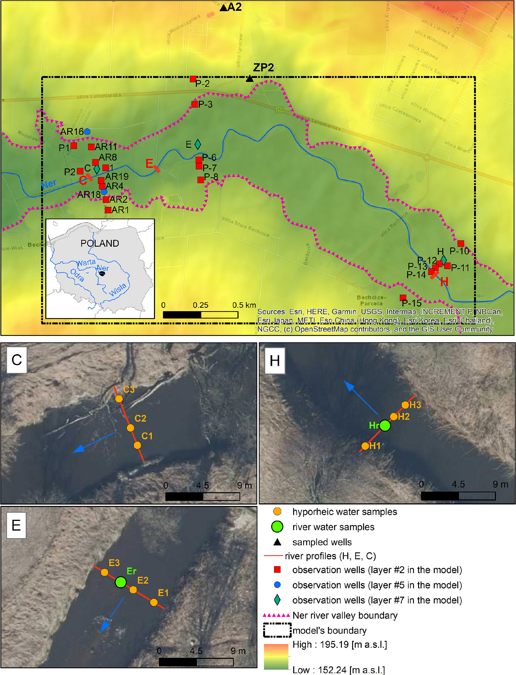
Fig. 1.
Locations of research profiles and sampling points.
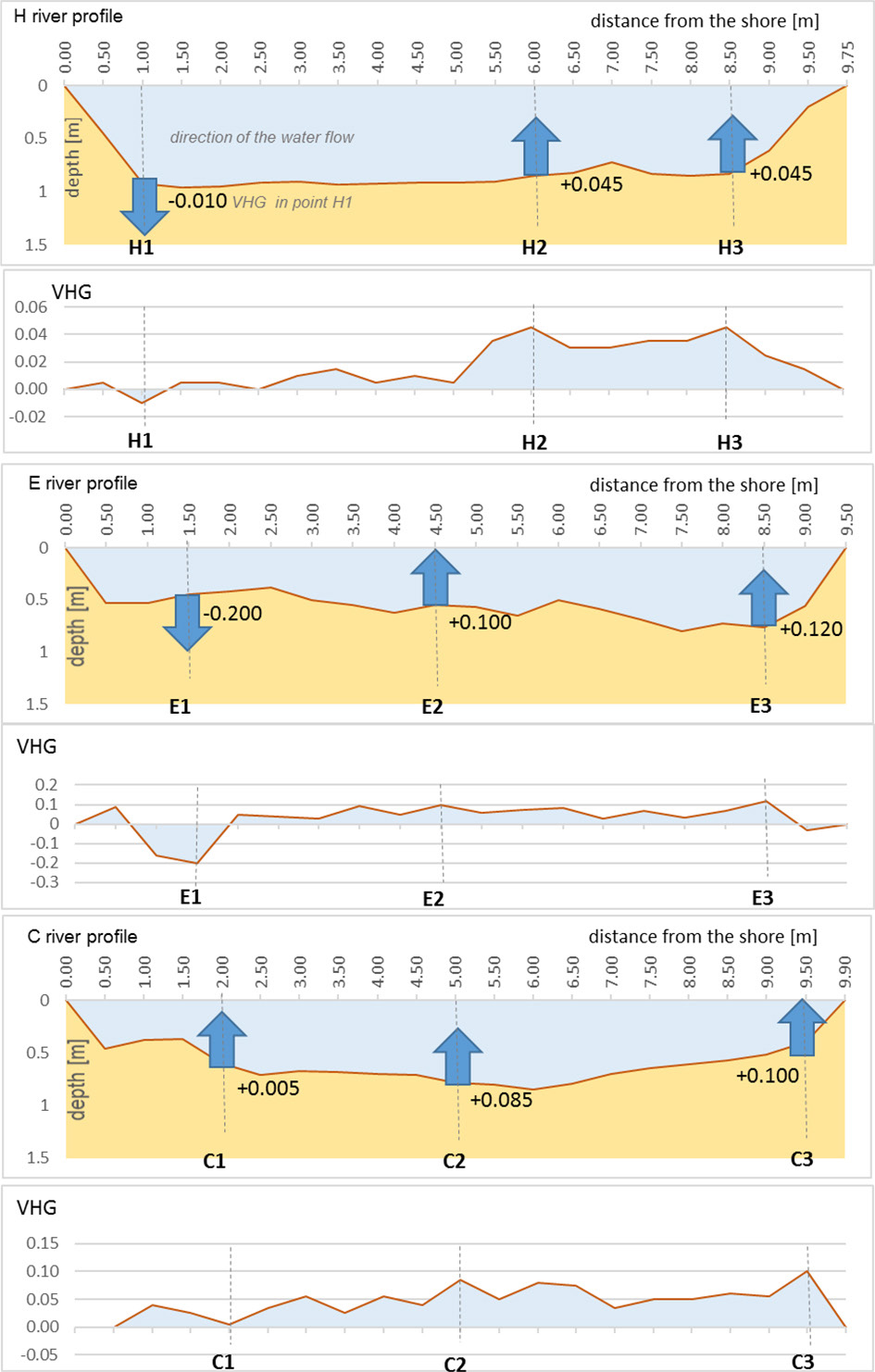
Fig. 2.
Vertical hydraulic gradients (VHGs) [m · m−1] and dominant directions of water flow in hyporheic zone (HZ) at locations where water samples were taken for chemical analysis (marked with arrows).
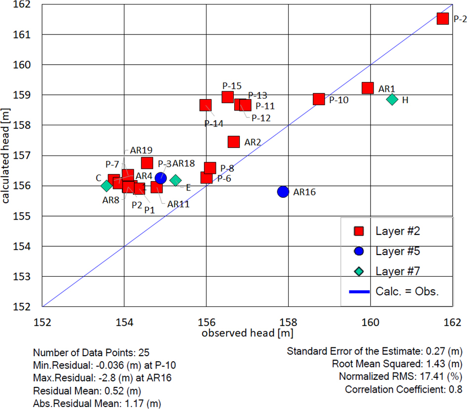
Fig. 3.
Model calibration graph.
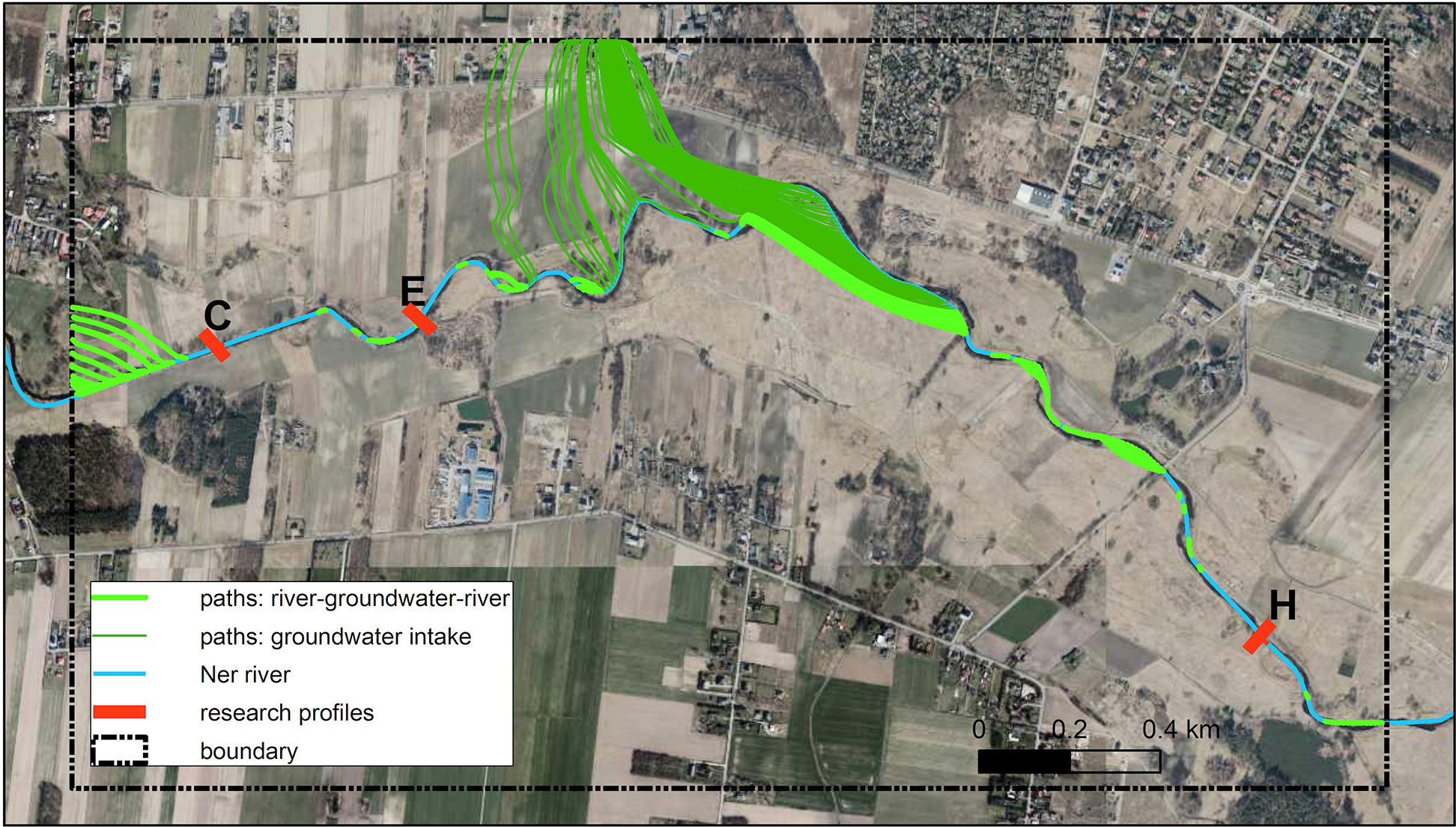
Fig. 4.
Infiltration zones of Ner River waters.
Table 1.
Characteristics of the hyporheic exchange flow (HEF).
| Parameters | Average distance | Minimal distance | Maximal distance | Standard deviation | Average travel time to drainage zone | Average velocity | Percentage of the river length |
|---|---|---|---|---|---|---|---|
| [m] | [a] | [m a−1] | [%] | ||||
| All paths | 389.48 | 10.57 | 1117.49 | 307.88 | 20.24 | 19.24 | 55.24 |
| Paths within Ner River drainage zone (light green in Fig. 4) | 143.42 | 10.57 | 566.88 | 138.23 | 12.86 | 11.15 | 29.41 |
| Paths to groundwater intake (dark green in Fig. 4) | 669.64 | 408.41 | 1117.49 | 183.13 | 28.63 | 23.39 | 25.83 |
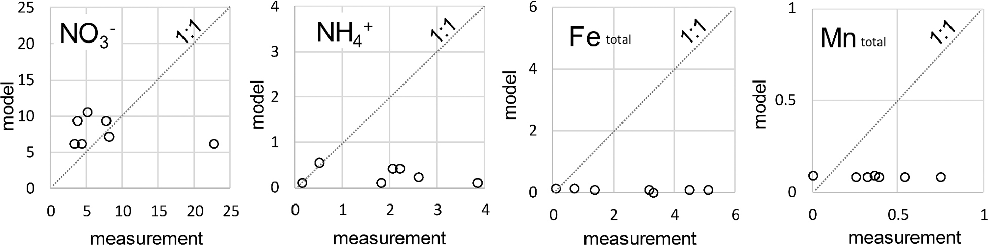
Fig. 5.
Comparison of laboratory-determined content of selected components in the hyporheic zone (HZ) waters with content calculated by hydrogeochemical models [mg · dm−3].
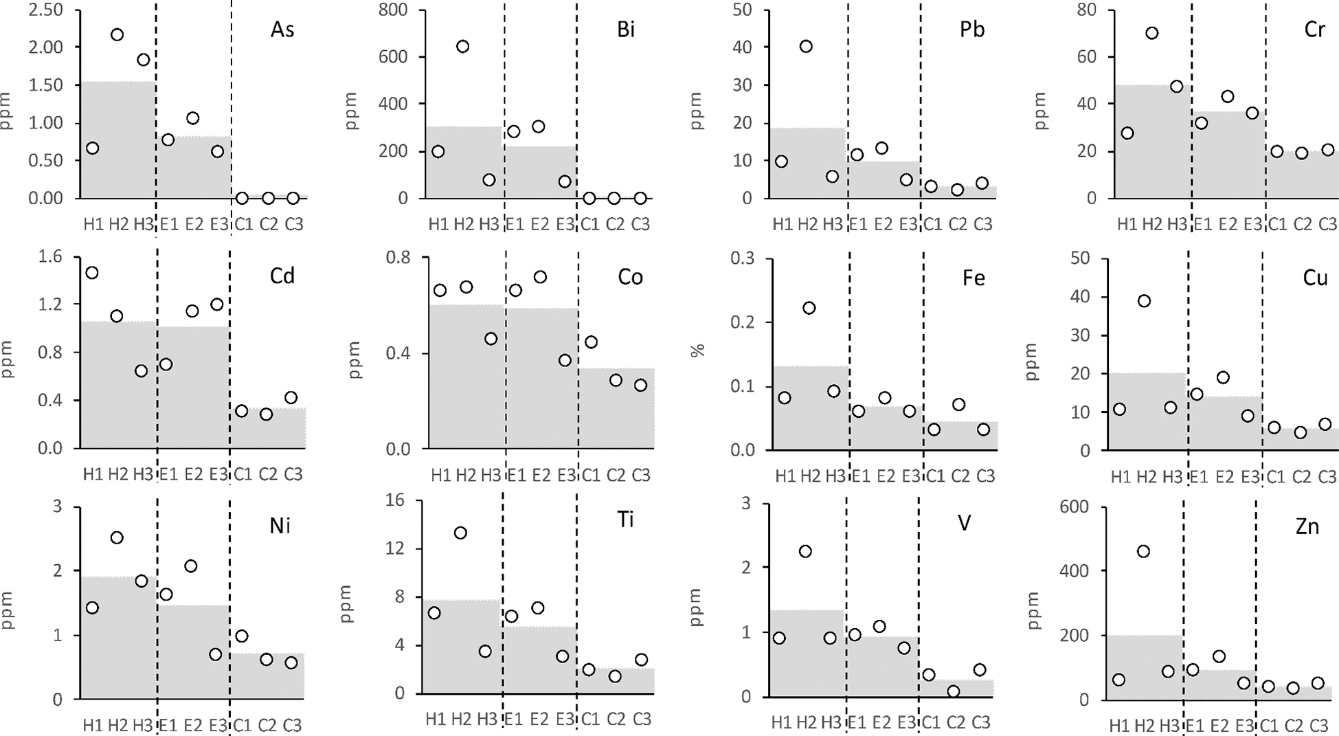
Fig. 6.
Concentrations of selected elements in the alluvium of Ner River (average values for each profile studied shown in grey).
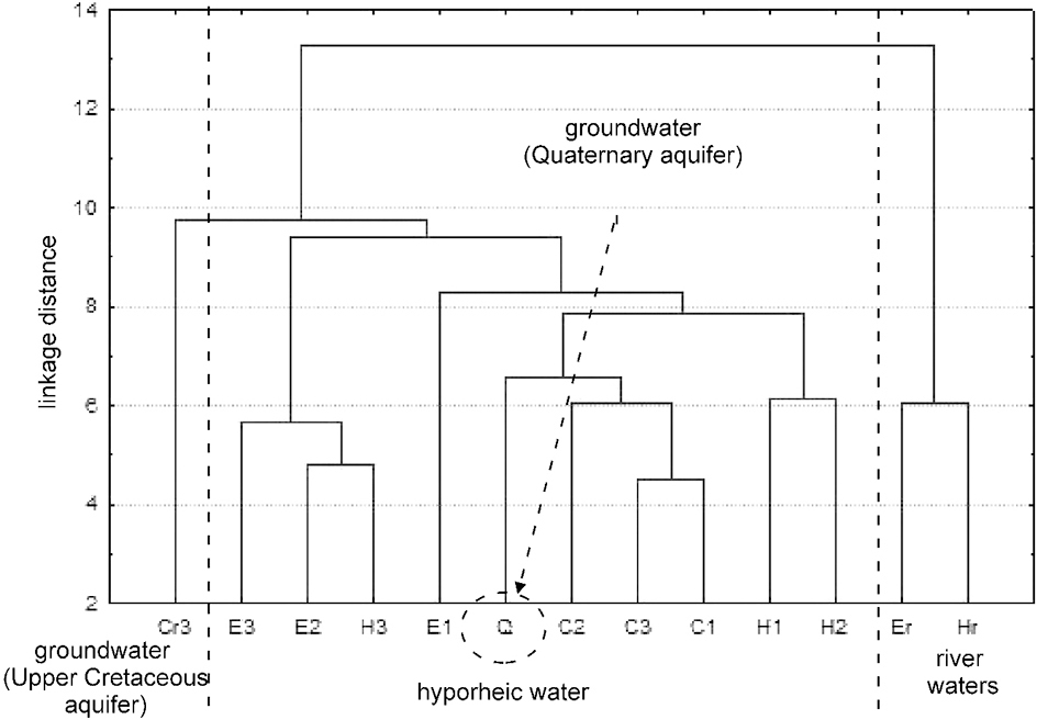
Fig. 7.
Dendrogram of hydrochemical similarity of the studied waters.