
1. Introduction
The construction of a hydrogen infrastructure brings with it new safety-related challenges. In order to evaluate emerging risks, extensive experimental and theoretical studies in the field of hydrogen safety were carried out at the KIT Institute for Thermal Energy Technology and Safety (ITES).
In tunnels and rooms such as underground car parks and factories, there is the possibility of fire fighting with permanently installed foam extinguishing systems or mobile foam extinguishing equipment. The extent to which firefighting with foam is suitable near hydrogen vehicles and other pressurized gas-powered machines has not yet been clarified. One scenario would be that after an accident with a hydrogen vehicle resulting in a fire, the vehicle is covered with extinguishing foam as part of the fire fighting. Leaking hydrogen could penetrate the foam masses and accumulate therein. This would create a foam containing hydrogen and air. It is also conceivable that foam solution settles over a leak, so that hydrogen flows into the solution and foams it up, which could result in foam with a highly enriched hydrogen content. There is up to now no technical application for flammable aqueous foams. The limited literature on this topic shows that such foams are entirely flammable. Burgoyne & Steel (1962) determined the ignition limits of foams filled with methane-air and found that the presence of the liquid foam structure narrows the range of ignitable methane concentrations. Baer, Griffiths and Shepherd (1982) found for their hydrogen-air foams that the ignition limits of lean mixtures are hardly affected by the foam structure. Zamashchikov and Kakutkina (1993) determined the speed of flame propagation in foams with 10 to 15% hydrogen content and a wide range of different liquid content and observed flame speeds of a maximum of 2.4 m/s. Kichatov et al. (2016; 2017) give an overview over relevant publications in this field. In literature, there are no studies of foam combustion over a wide range of hydrogen concentrations, especially for rich mixtures and in general devoted to firefighting foam solutions.
The goal of this experimental work is the investigation of fundamental burning behavior of H2/air flames inside foam. Therefore, systematic tests were performed in transparent and vertically oriented cylindrical open-end tube (d = 0.09 m; 1.5 m length) and in a rectangular thin layer open-end channel (0.02 m × 0.2 m; 2 m length) for a wide range of hydrogen concentration (8 to 70% H2 in air). Two different foaming agents with varying concentration were studied in this work. A commercial standard family bubble bath foam and a professional firefighter extinguisher foam with foam expansion rates from 20 to 50. For the realistic point of view, in addition to the small-scale tube tests, a limited number of larger scale experiments in horizontal pool geometry (0.30 m × 1 m × 2 m) were performed with H2/air concentration up to stoichiometry. High-speed imaging is used to observe the combustion behaviour and to determine flame velocities. The focus is on flammability limits and flame acceleration. Finally, to answer the question if detonation is possible in fuel enriched foam few small-scale experiments performed with H2/O2-mixtures.
2. Experimental Set-Up
2.1 Foaming agents
The use of foam in firefighting technology is on a very high professional level. Many different foam agents and foam generators for different applications are available on the market. Foam itself is not a uniform medium. A foam is commonly defined as a dispersion of gas bubbles in a liquid. In general, it is water, gas, foaming agent and mechanical energy necessary to create aquatic foam. In this work deionized water and a defined H2/air mixture flow, provided by mass-flow-controller, used to create foam at ambient temperature and pressure. Two different foaming agents were investigated in this work. A professional firefighter extinguisher foam concentrate (STHAMEX®-class A Classic 1% F-15) especially designed for extinguishing solid material (class A) fires and use with compressed air-foam technology (CAFS). This STHAMEX® class A agent can also be used for non-polar class B fuels (e.g., diesel or petrol) as low- and medium-expansion foam and is suitable to extinguish a car fire. The extinguishing foam STHAMEX® class A is described as fluorine-free, physiologically harmless, and fully, very easily biodegradable but on the other hand, a special wastewater treatment is required on the test side using firefighter extinguisher foams. To reduce the waste production to a minimum a second, completely harmless, commercial standard family bubble bath concentrate was used in this work.
2.2 Combustion facilities
The used foam generators were directly integrated inside the combustion facilities. The sketches in Figure 1 show the different combustion ducts and its periphery. The horizontal pool geometry (Figure 1, left) consists of a stainless-steel pool (0.30 m × 1 m × 2 m) with an adapted foam generator on the bottom side. The reservoir of the foam generator can hold up to 15 dm3 water foam concentrate mixture (foam solution). On its bottom several small porous stones were mounted, see Figure 2(d). A constant, premixed H2/air mass flow (100 STP dm3/min) passed through the porous stones into the solution and creates foam above the liquid level. This pre-foam has a very amorphous structure and includes large instable bubbles. The connection of the foam generator to the combustion pool is realized with a 10 mm porous metal sintered plate, see Figure 2(e). After the pre-foam is squeezed through the sintered plate, it has a relatively uniform structure, in particular almost uniform stable bubble sizes. Another task of the stable sintered plate with very fine porosity is to protect the foam generator from flashback.
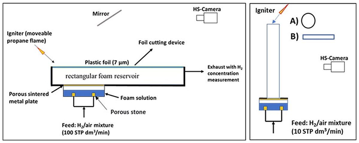
Figure 1
Left, large-scale pool. Right, small-scale tubes, circular A) and rectangular B).
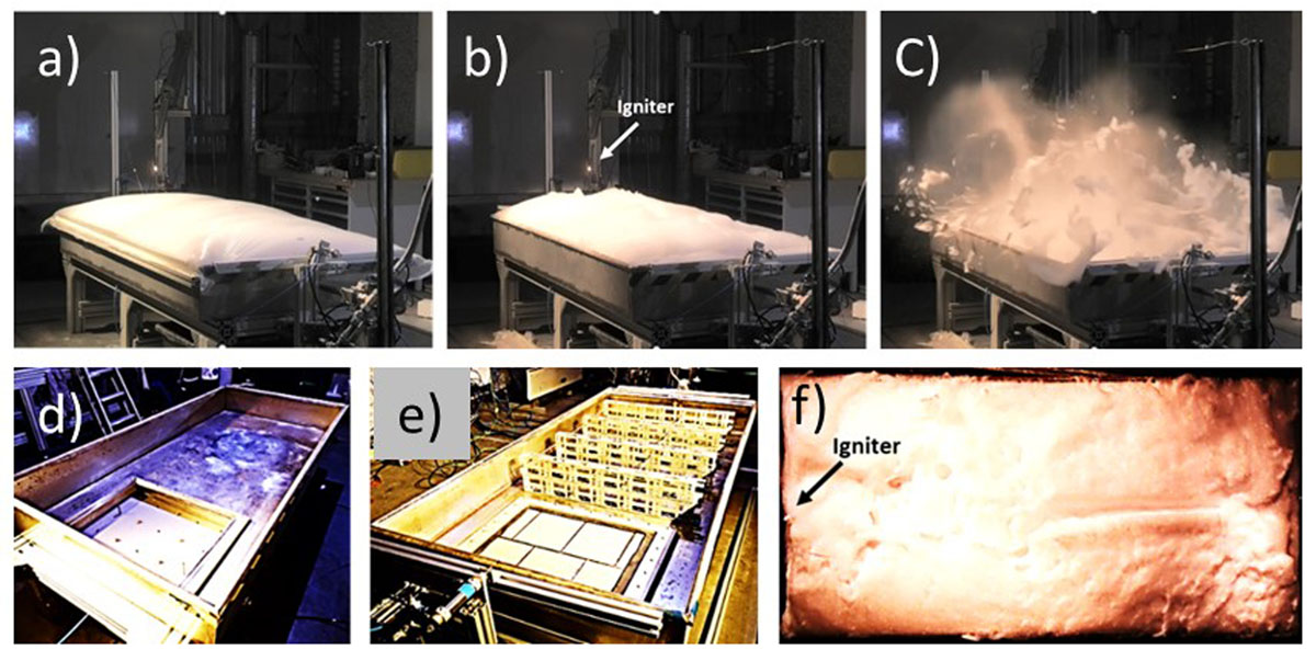
Figure 2
(a) Pool filled with foam and covered with foil; (b) Pool filled with foam and removed foil; (c) Snapshot after ignition. (d) Empty pool with open foam generator. (e) Empty pool with sintered plate covered foam generator and obstacle lines. (f) Snapshot from high-speed video (2000 f/s).
In order to fill the pool completely with foam, it is necessary to direct the foam flow horizontally. For this reason, a thin foil (7 µm) covered the pool. The foam filling procedure with 100 STP dm3/min gas-flow takes a time of 5 min. During this time, the H2-concentration in the squeezed-out atmosphere is measured continuously. Remarkable is the very low measured H2-concentration below 1% in all cases. Figure 2(a) shows the foam filled pool covered with the thin plastic foil. Shortly before the ignition, the foil is removed via a foil cutting device, Figure 2(b). The ignition source is a 2 cm long laminar propane diffusion flame, which immersed in the foam mass at the front end. The snapshot Figure 2(c) shows the ignited foam, the pool is fully open at the top. To observe and to measure the combustion behaviour, the foam surface of the pool was recorded via a mirror above the pool with a high-speed camera. Figure 2(f) shows a picture from a high-speed movie (2000 f/s) of the foam surface shortly before the ignition. Most of the experiments were performed in an unobstructed pool. To investigate the influence of obstacles in the flame path, the pool can be equipped with 50% blockage ratio, see Figure 2(e).
The sketches in Figure 1 right, show the small-scale vertical tube facility. The principle of the foam formation is the same as in the pool facility. The reservoir can hold up to 5 dm3 foam solution and the feed gas flows of the pre-mixed H2/air are fixed to 10 STP dm3/min. Two different transparent (Plexiglas) combustion channels can be adapted above the sintered plate of the foam generator. One is a rectangular thin layer open-end channel with a cross section of 0.02 m × 0.2 m and a length of 2 m, Figure 3(a) and the second a circular tube with an inner diameter of 0.09 m and a length of 1.5 m, Figure 3(c). The constant pre-mixed H2/air flow can be switched from a bypass through the foam generator and the generated foam rises with constant velocity to the open end of the tube, the filling time is ~1 min. The tubes will be slightly overfilled, a metal sheet round the open end takes the overflow. The ignition source is also a 2 cm long laminar propane diffusion flame, which immersed in the overflow foam mass at the open channel end. To observe and measure the combustion behaviour of the foam in the tubes, a high-speed camera is used. Figure 3(b, d) show snapshots from the high-speed movie from both channel configurations. In several experiments, three PCB pressure sensors were installed in the rectangular thin layer channel.
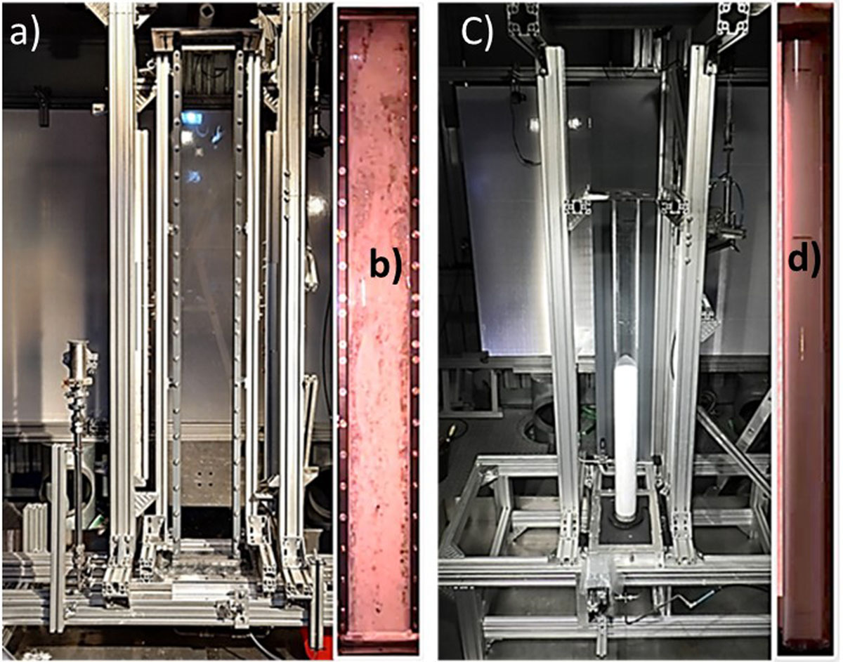
Figure 3
Small-scale vertical tube facility. (a) Rectangular thin layer configuration; (b) Snapshot from high-speed video, rectangular thin layer; (c) Circular tube configuration during foam filling; (d) Snapshot from high-speed video, circular tube.
2.3 Foam properties
Several properties are important for the characterization of foam, such as bubble size distribution, foam stability, and foam density. The used foaming agents are special professional products. It was found that the method of foam generation could influence the foam properties significantly. Due to the fixed method of foam formation, the variation of the foam properties is limited. All measurements of the foam properties were directly performed in the combustion facilities. Foam itself is not a uniform medium and after the production a rapid starting foam aging takes place. Due to the drainage of liquid with time, the foam density decreases with time. Figure 4 (left) shows the decaying foam density versus the run-time of foam generator (small-scale facility) for different gas-flow rates (air) using extinguisher agent concentrate (1 vol. %). The foam density was measured gravimetrical by taking samples on the open end of the circular tube. With increasing gas-flow rates the foam density increases but all foam densities decrease with time. Above gas-flow-rates of 20 dm3/min large gas bubbles (empty space) were observed inside the tube. The visual best foam uniformity was observed for a gas-flow rate of 10 dm3/min in the small-scale facility and respectively 100 dm3/min in the larger pool facility. The variation of the foaming agent concentration shows a limited influence on the density of the created foam. Figure 4 centre shows the decaying foam density versus the run-time of foam generator (small-scale facility) for different extinguisher agent concentrate and gas-flow rates (air) of 10 dm3/min. All foam densities decrease with time and the differences of the foam densities gained from the different foam solutions are low. In addition, the run-time of the foam generator is very long. In the combustion experiments, the level of solution inside the foam generator was controlled and refilled before each experiment and the run-time of the foam generator is in the range of 1 min. It can be also assumed that inside the tube exists a vertical density gradient. To measure the average foam density at the time of ignition, the entire foam-filled tube (gas-flow rate 10 dm3/min) was taken from the facility and was weighed. Figure 5 left summarized the results for the family bubble bath foam. The measured foam density of ~20 kg/m3 is independent of the foam agent concentration.
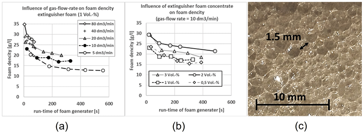
Figure 4
Left, example of foam density vs. run-time of foam generator for different gas-flow rates. Center, example of foam density vs. run-time of foam generator for gas-flow rate (10 dm3/min) for different extinguisher agent concentrate. Right, picture of extinguisher foam (2% extinguisher agent concentrate; gas-flow rate 10 dm3/min).
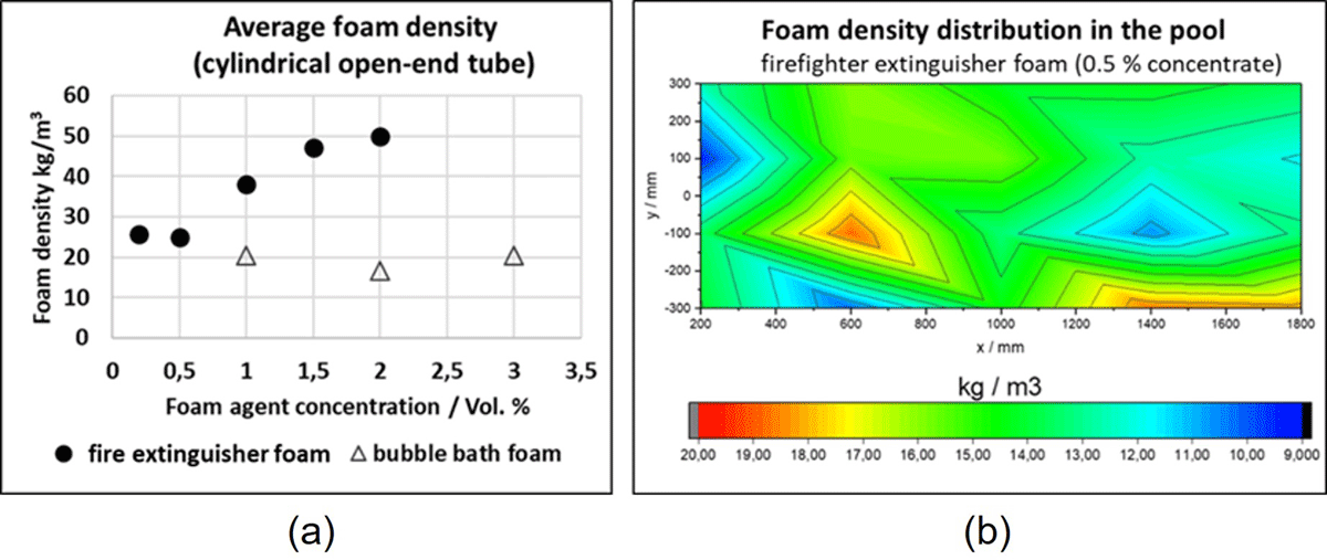
Figure 5
Foam density. Left, average foam density in the small-scale circular tube vs. foam agent concentration. Right, example of foam density distribution in large-scale pool.
In contrast, the fire extinguisher foam density increases with increasing foam agent concentration. Figure 5 (right) shows the foam density distribution in the large-scale pool for the extinguisher foam with 0.5% concentrate. The measured density distribution is uniform and in average 15 kg/m3. Due to the pool filling time of 5 min the drainage effect in the pool is stronger as in the tubes where the average foam density for extinguisher foam with 0.5% concentrate is 25 kg/m3. In summary all experiments performed with medium expansion foam (foam expansion ratio is in a range of 20 to 200). The foam generator produces serviceable foams using solution concentration between 0.5% and 2% (extinguisher agent) and 1% and 3% (family bubble bath agent). The visual differences of the foam variations are limited, Figure 4 right shows exemplarily the foam structure (2% extinguisher agent concentrate; gas-flow rate 10 dm3/min), the most bubbles have sizes in the range of 1.5 mm but sometimes the bubble size is much larger.
3. Results
The foams created with H2/air-mixtures burn very well. A typical combustion scenario is shown exemplarily in Figure 6 with a 25 vol.% H2 in air for firefighter extinguisher foam (0.5%). The left side shows the picture from the high-speed movie (2000 f/s) at the time of ignition. The right side shows the combustion process in x-direction (1D centre-line) as a stack montage from the movie. The montage visualizes the flame front propagation as a distance-time diagram. After the ignition, the flame velocity is first low. Up some point (Hot spot), the flame velocity changes rapidly, the flame front propagates nearly constant with a faster velocity to the pool end.
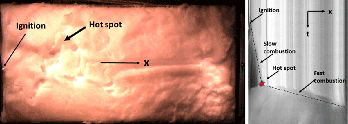
Figure 6
Left, snapshot from the high-speed movie (2000 f/s) at the time of ignition. Right, stack montage from the high-speed movie as distance-time diagram (25% H2 firefighter extinguisher foam 0.5%).
The stack montage from the high-speed movie as distance-time diagram (Figure 6, right) shows the combustion process in 1D (centre line x). The picture series in Figure 7 taken from a high-speed movie shows the combustion process in 2D inside the horizontal pool as a top view. The flame propagates after the ignition slowly in a hemispherical manner up to the position of the hot spot. The position of the hot spot is clearly visible, the flame velocity increases rapidly and a circular shock front is visible.
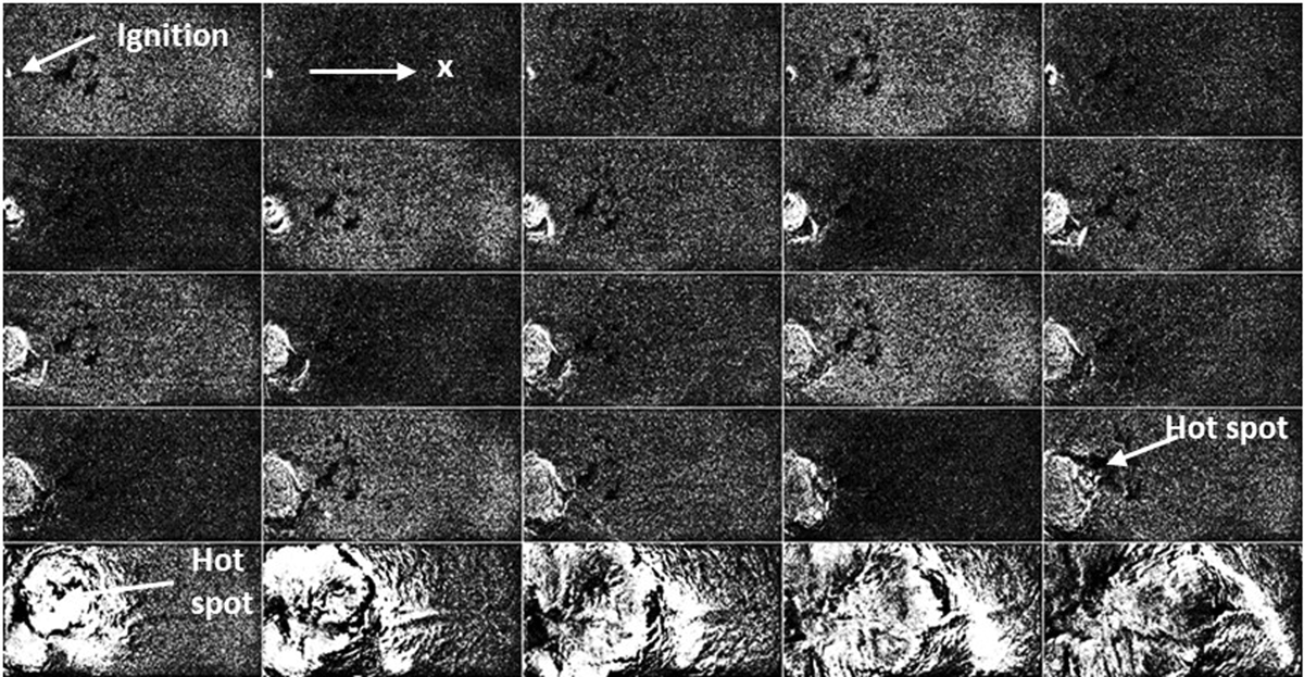
Figure 7
The picture series high-speed movie (25% H2 firefighter extinguisher foam; time step between frames = 6 ms).
For a lower H2-concentration (<25% H2) inside the foams, the effect of rapid flame acceleration was not observed, independent of an obstacle setup in the pool, Figure 2e. For a 20% H2 foam, corresponding to a family bubble bath 1% for foam generation, a nearly constant average flame velocity of 16.6 m/s was observed in the configuration with and without obstacles in the pool. This indicates that the combustion inside the foam is not sensitive to obstruction.
The observation of the flame front propagation in foam is inside the transparent small-scale tubes substantial superior as in the larger pool. Examples are shown in Figure 8, where the ignition is on the top (x = 0) and the flame propagates downwards. The left side shows the combustion process (23% H2; bubble bath 1%) as time distance plot in the transparent channel (d = 90 mm). The flame burns after the ignition first with a constant slow velocity up to a ‘hot spot’ point. At this point, the flame velocity changes into a faster and constant propagation mode. On such plots, it is visible, that exactly from the transition point an emission of a shock wave (SW) in the unburned foam takes place. The shock wave velocity is higher than the flame propagation velocity. The Stack montage on the right side of Figure 8 shows a time distance plot of a more reactive mixture (40% H2; bubble bath 1%). In this example, the hot spot takes directly place with or shortly after the ignition. The first emission of a shock wave (SW) propagates through the whole channel. The flame front propagates with a constant velocity. During the fast flame propagation, new shock waves were generated continuously in a nearly constant frequency.
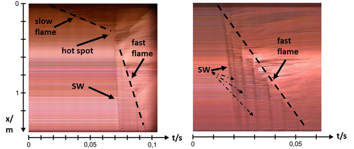
Figure 8
Stack montage from the high-speed movie (4000 f/s) as distance-time diagram. (Small transparent channel (d = 90 mm); family bubble bath 1%). Left, 23% H2; Right, 40% H2.
Generally, three different combustion behaviors are observed in the experiments. 1) For lean mixture (<~20% H2) and rich mixtures (>~60% H2) the flame velocity is constant and low. 2) For high reactive mixtures (>~28% H2 to <~50% H2) the flame velocity is in a fast mode directly initiated by the ignition. 3) For the other mixtures in the transition zone, the flame velocity starts first slowly and accelerates rapidly on a hot spot point. Figure 9 shows the run-up-distance (x) of the flame up to the hot-spot point inside the transparent channel (d = 90 mm) for the bubble bath and fire extinguisher foams. Is the run-up-distance given as 1.5 m, no transition of the flame velocity takes place, in this case the flame burns only in a slow mode without acceleration. Is the run-up-distance marked as zero, the fast flame propagation mode is directly initiated by the ignition or the run-up-distance is very short. An influence of the different foaming agent’s concentration on the run-up-distance was not detectable. The comparison of the bubble bath and fire extinguisher foams shows a more and bright scattering of the run-up-distance for the bubble bath foam.
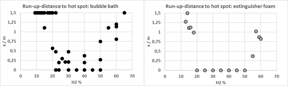
Figure 9
Run-up-distance (x) of the flame up to the hot-spot point inside the transparent channel (d = 90 mm) for the bubble bath and fire extinguisher foams.
In all experiments nearly constant flame velocity is observed, a continuously flame acceleration takes not place. Only the abrupt rise of the flame velocity due to hot spot event is recognized. Figure 10 summaries the results for the maximum flame propagation velocities in family bubble bath and the fire extinguisher foam respectively. The measured flame velocities in the horizontal larger pool experiments (red triangles) are in good agreement with the values measured in the vertical smaller tube. On the data from the family bubble bath, it is visible that the flammability limits of the foam lies at LFL =< 9% H2 and UFL => 65 H2. It indicates that under consideration of downwards propagation, the flammability limit in foam is very close to the flammability limit of the H2/air gas mixture (Kumar, 1985). The differences between the two investigated types of foam were surprisingly low. In general, the flame propagation velocity increases slowly, starting from the LFL (~9% H2), up to the H2-concentration ~20% H2 but it lies above the laminar flame velocity of the pure gas. The rapid transition of flame velocity occurs at the hot spot. The maximums of flame velocities (~<100 m/s) are observed at near stoichiometric conditions. With further increase of H2-concentration, the flame velocities decrease continuously.
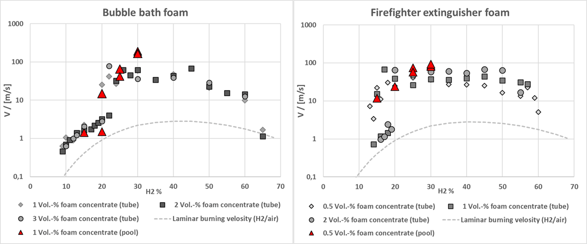
Figure 10
Flame propagation velocities in family bubble bath (Left) and the fire extinguisher foam (Right).
In the cases when flame velocity reaches the fast propagation mode, emission of shockwaves (SW) is observed. The optical measured speed of sound in the foams (Figure 8) is plotted in Figure 11. The speed of sound inside the foams is nearly constant for different H2-concentrations in the gas phase. It manifests that the speed of sound is nearly independent of the gas mixture in the foam. However, the speed of sound in the normal gas mixtures increases noticeable with increasing H2-concentration. The comparison of the bubble bath and fire extinguisher foams shows that the speed of sound of extinguisher foams lies below the speed of sound of bubble bath foams. For the fire extinguisher foams it is visible, that the foam with 1% foam concentrate has the lowest speed of sound (<100 m/s) while the foam with 0.5% foam concentrate reaches ~150 m/s and the foam with 2% concentrate lies in between. In general, the extinguisher foams show values that are more constant over the whole H2 concentration range as the more scattering bubble bath foam data. This indicates a more uniformity of the extinguisher foam.
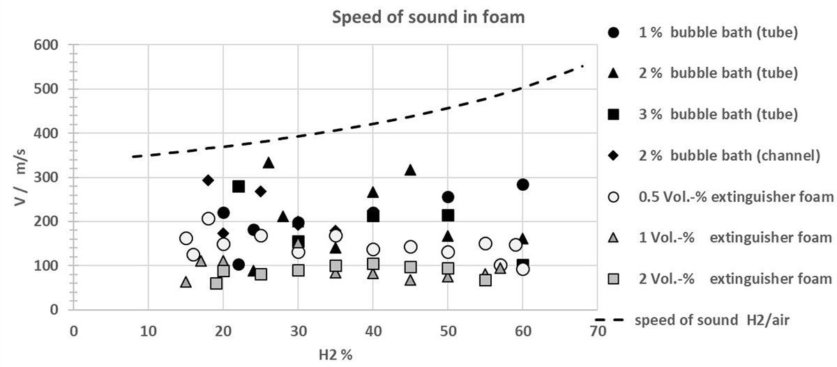
Figure 11
Speed of sound in the foams.
The combustion overpressure measured in the rectangular thin layer open-end channel with a cross section of 0.02 m × 0.2 m and a length of 2 m (Figure 3(a)). Figure 12 left shows a stack montage from the high-speed movie (4000 f/s) as distance-time diagram with signals of the three pressure gauges (P1 to P3) mounted in the channel (30% H2; fire extinguisher foam 0.5%). The overpressure detected from Sensor P1, near the ignition point and the open-end of the channel is all times low, in contrast to the sensor P3, located near the closed (porous sintered plate), which shows remarkable high-pressure loads(>1 bar). On the right side of Figure 12, the measured overpressure plotted versus the H2-concentration in the fire extinguisher foam (0.5%). The data from sensor P2 and P3 reflects the corresponding data from the flame propagation velocity shown in Figure 12 right.
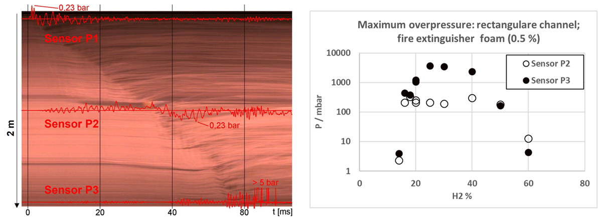
Figure 12
Left, stack montage from the high-speed movie (4000 f/s) with signals of the three pressure gauges. Right, maximum overpressure vs. H2-concentration in the fire extinguisher foam 0.5%.
An onset of detonation was not observed by using H2/air-mixture. Nevertheless, by using higher reactive H2/O2-mixture the burnable foam mixture easily detonates. Figure 13 shows exemplary the combustion of a family bubble bath foam (2%) filled with 50% H2 in O2. The picture series show the flame propagation inside the rectangular (cross section of 0.02 m × 0.2 m) vertical 2 m high channel with a frame rate of 10000 f/s. The combustion starts first in a fast mode, DDT occurs between frame 4 and 5. The measured detonation velocity is 1180 m/s, which is less than the half of the theoretical detonation velocity (CJ = 2324.5 m/s) of the pure H2/O2-mixture. Nevertheless, the reaction front propagates in a supersonic mode through the reactive foam. The large liquid part and the cellular foam structure is not able to suppress the shock wave driven reaction propagate of a gas detonation. Therefore very high-pressure loads and high temperatures inside the burnable foam are possible is case of an onset of detonation.
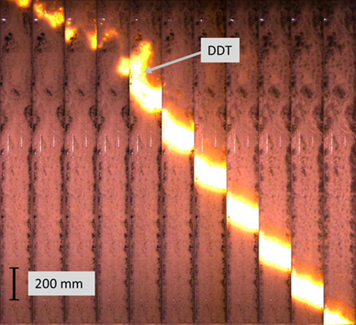
Figure 13
Picture series of the combustion of a family bubble bath foam (2%) inside the rectangular (cross section of 0.02 m × 0.2 m) vertical 2 m high channel (50 vol.% H2 in O2; 10000 f/s).
4. Discussion
Foam itself is a very complex fluid, it is an irregular structure build from liquid and gas. The generation of liquid foams is very important for many natural, technical or scientific processes (Drenckhan and Saint-Jalmes, 2015). However, there is no technical application for flammable aqueous foams and burnable or explosive fire extinguisher foam is a curio itself.
The flammable aqueous foams can be modeled as a cluster of soap bubble. It can be assumed that, if the gas in one bubble reacts, the separation soap film should be ruptured to ignite the gas in the neighbor bubble. Due to the small size of the bubbles and all times new start of the ignition inside the next bubble no flame acceleration will be observed and the geometries of the combustion ducts play no role for the flame propagation velocity of the foam. This simple model is able to explain the observed constant low flame propagation velocity inside the foams.
Figure 14 shows all low flame propagation velocities measured in this study, independent if the flame later on accelerates due to a hot spot event. The course of the points describes the line from the root of the products from the laminar burning velocity (SL) and the expansion factor (σ) of the pure gas mixtures (Kuznetsov et al., 2012).
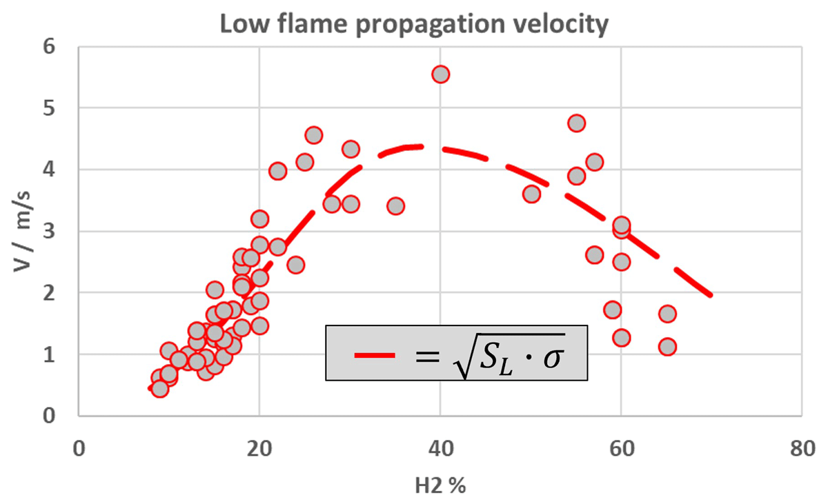
Figure 14
Low flame propagation velocity measured in this study.
No simple model was found to describe the mechanism of the observed hot spot events with a rapid change to faster and almost constant flame propagation velocity. Detailed high-speed imaging (30000 f/s) of bubble cluster shows strong oscillate bubbles in the unburned foam in front of the reaction zone. A flame front travel in ruptured bubbles in the faster combustion mode was not resolvable with the high-speed capturing. However, it can be assumed that some kind of preconditioning of the unburned foam, pushed from the flame front, is the reason of the onset of a hotspot and the rapid change of the flame propagation velocity. There are still many open questions.
The study shows that the combustion behaviour of the investigated foams is very different in comparison to the pure H2/air-gas-combustion. The foam suppresses radical the typical self-generated flame acceleration of H2/air. On the other hand, the foam is able to store a H2 fuel mixture in unconfined environments. Especially in fire fighter foam with special stabilisation additive is the mixture several hours ignitable. The H2 combustion inside foam leads also to lower thermal loads as the pure H2/air-gas-combustion, due to the large amount of water in the foam. Due to the combustion, the foam will be destroyed and the liquid phase splashes partially in the environment and accumulate on the ground. Only a small part evaporates.
This work deals only with the combustion behaviour of foam and not with the probability that the use of foam solution in combination with leaking H2 produces burnable foam. But one technical application is the traditional leak search method, using soap solution—on the leak you see bubbles. There are many methods to produce foams (Drenckhan and Saint-Jalmes, 2015). The use of extinguishing foam in combination with leaking gas fuels should be handled with extreme caution.
5. Summary and Conclusions
This work investigates basic fundamental burning behaviour of H2/air flames inside fire extinguisher foam. Therefore, defined foams were created by using premixed H2/air-mixtures, water and professional foam agent concentrate. In addition to a professional fire-fighting foam, a family bath foam was studied. The foams ignited in three different ducts under variation of the H2-concentration and foam agent concentrate.
The main conclusion of this work is that foam built with H2/air-mixture becomes burnable. H2 gas can be confined for several hours inside foams. There is no buoyancy effect and rapid dilution. The flammability limit in foam is comparable with the flammability limit in pure gas. For reactive mixtures of ~>20% H2 and <50% H2, a special sudden flame acceleration due to hot spots was observed. The maximums of flame velocities of ~<100 m/s were observed near stoichiometric conditions in all of the three investigated ducts. Detonation of foam enriched with H2/air-mixture was not observed; however, foams enriched with H2/O2-mixture easily detonate.
Acknowledgements
This research has received funding from the Fuel Cells and Hydrogen 2 Joint Undertaking (now Clean Hydrogen Partnership) under Grant Agreement No 826193 (HyTunnel-CS project). This Joint Undertaking receives support from the European Union’s Horizon 2020 Research and Innovation program, Hydrogen Europe and Hydrogen Europe Research.
Competing Interests
Thomas Jordan is the Editor in Chief of Hydrogen Safety. He was removed from all editorial processes in handling this paper. The authors have no other competing interests to declare.