
1. Introduction
From 2005 to 2019, the US digital economy grew at an average annual rate of 6.5%, outpacing US economic growth by ~360% (Sartor et al., 2023). Data centers, which are comprised of servers, data storage drives, and network equipment, are a key part of the ever-expanding digital economy. In 2020, the data center industry had a valuation of $8.4 billion and was estimated to grow to $13.9 billion in 2026 (Sartor et al., 2023). While the Information and Communication Technology sector has grown to meet the demand for data storage, this development has caused data centers to ‘become a major consumer of energy and an agent in the escalation of fuel prices’ (Shuja et al., 2012). In 2020, the International Energy Agency (IEA) estimated that data centers used between 240–340 TWh of electricity globally, accounting for 1.0–1.3% of the global electricity demand (2023). The carbon footprint associated with this electricity use is heavily dependent on how the electricity is produced and where the data center is located.
Backup power is critical for data centers, ensuring that systems remain operational in the event of a power outage. Data center operators could also use backup power generators as a source of energy during peak load times, reducing the strain on the local electric grid (Peng et al., 2022). Downtime from power outages or component failure can be very costly, with 60% of failures costing $100,000 and 15% of failures over $1,000,000 (Uptime Institute, 2022). These numbers have risen substantially since 2019, indicating a growing need for reliable backup power systems (Uptime Institute, 2022).
Currently, most data center backup power is provided by diesel generator sets, also known as gensets. Although it is an effective and robust method for providing backup power, gensets produce 1.22 kg CO2/kWh, as well as other pollutants that are hazardous to human health (NOx, particulate matter, etc.) (Jakhrani et al., 2012). Backup systems must be regularly tested per National Fire Protection Agency (NFPA) 110 to ensure the system remains functional in the case of a power outage. Typical agreements offered by data centers stipulate having fuel onsite to run for 48 hours in the event of a power outage.
Utilizing hydrogen as a backup power source at data centers is one way that operators can provide safe and resilient energy. Large-scale hydrogen demonstration projects enable proof of concept and validation of early-stage commercial hydrogen technologies. These projects not only show the feasibility of utilizing hydrogen as a reliable backup energy storage technology but also provide opportunities to identify unforeseen challenges and conduct workforce development.
In 2015, as part of a previous project, National Renewable Energy Laboratory (NREL) deployed 852 hydrogen backup generators at data centers across 23 states. Even though these generators had an average site capacity of 4–6 kW, which is substantially smaller than the current project, the overall 99.5% start ratio and continuous 65-hour run time showed that hydrogen could meet the requirements for backup generators (Kurtz et al., 2015).
In 2023, Caterpillar led a development and demonstration project with funding from the Department of Energy’s (DOE) Hydrogen and Fuel Cell Technology Office (HFTO) to deploy a 1.5 MW Proton Exchange Membrane Fuel Cell (PEMFC) at a data center for backup power. Caterpillar, along with Ballard Power Systems, Microsoft, and the NREL, successfully deployed the 1.5 MW PEMFC at a Microsoft data center to demonstrate hydrogen’s viability as a backup power source. This demonstration explored the technical challenges, safety, and economic factors associated with hydrogen backup power and deploying a full-scale system at an operational data center.
The successful deployment of a hydrogen system goes beyond the installation and operation of robust hardware. Safety reviews, siting consideration, permitting requirements, construction, commissioning, and the overall safe operation of hydrogen systems combine for a successful and safe deployment. The demonstration of a large-scale fuel cell at a data center is an excellent case study from which the lessons learned can be shared to help guide future deployments of hydrogen systems at scale.
Here, we explore the lessons learned from deploying liquid hydrogen in a backup power application, so that others can successfully implement hydrogen as a backup power source for data centers and other critical infrastructure.
2. Materials and Methods
2.1 Fuel cell demonstration project
In this demonstration, Ballard Power Systems developed a 1.5 MW PEM FC. Caterpillar was the systems integrator and provided the energy storage system (ESS) and microgrid controller. Linde supplied the LH2 storage tank and hydrogen. Microsoft was the data center host and McKinstry completed the engineering, procurement, and construction (EPC). The subsystems were commercial or near-commercial components which were integrated in a novel configuration.
This demonstration occurred in the fall of 2023 in Cheyenne, Wyoming. The unique weather of the region allowed the demonstration to operate the large fuel cell in warm, dry weather and cold, snowy weather, as seen in Figure 1. During the demonstration, researchers observed temperatures as low as 12°F, shown in Figure 2. Even in these challenging weather conditions, and at an altitude of 6,068 ft (1855 m), the fuel cell system met the performance targets of the demonstration. The project team was able to operate the system safely, achieving zero Occupational Safety and Health Administration (OSHA) recordables. This success can be attributed to the project team’s safety planning and execution.
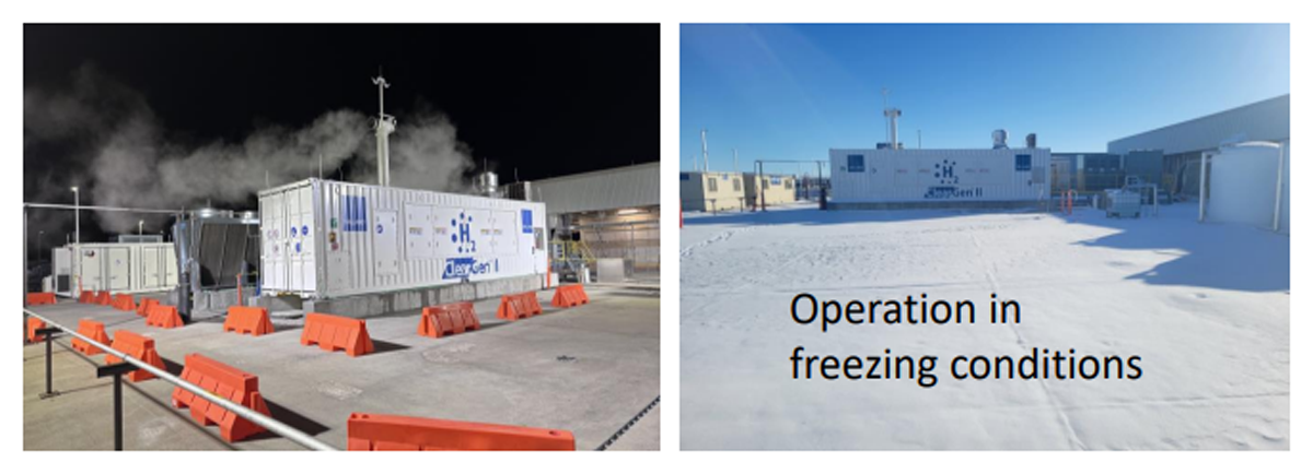
Figure 1
The hydrogen fuel cell operated in freezing conditions (left and right), including following snowfall (right) at the datacenter (Wang and Manda, 2024).
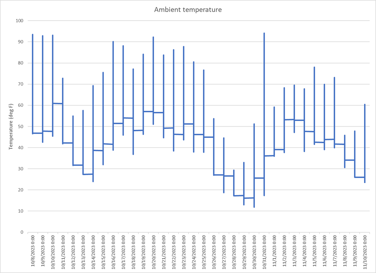
Figure 2
Ambient temperature measurements at the site.
The data center in which the hydrogen system was deployed can be described as an active and fully operational data center. An older portion of the data center that was being decommissioned was used as the demonstration site. The electrical spine/infrastructure remained, which was connected to switchgear. The switchgear was also connected to the 1.5 MW fuel cell, two ESS units each rated at 1.25 MW (peak), and a load bank allowing for islanded operation. The footprint required for the demonstration equipment was approximately 300 ft × 100 ft.
For the demonstration, the data center host required that the hydrogen system be able to support a 48-hour backup power event. Liquid hydrogen was chosen as the storage medium to reduce the footprint and cost of the backup power system. An 18,000-gal LH2 tank, which holds approximately 4,200 kg, provided the capacity to power the fuel cell for 48 hours of continuous operation at an average power output of 1.125 MW. This tank also enabled the demonstration of the fuel cell’s ability to meet the data center host’s and project requirements without exceeding the mass storage limits established in OSHA’s 29 CFR 1910.119. Given additional bulk storage or LH2 deliveries, the fuel cell system could run continuously during a power outage of any duration.
Factors such as safety (e.g., setbacks, handling, etc.), access control (e.g., access for delivery drivers, limiting exposure to unrelated employees), and stability/reliability (e.g., boiloff rates and replenishment) were closely considered when determining the location of the liquid hydrogen tank. To enable successful integration of the liquid hydrogen system with the fuel cell, specific system information (e.g., temperature concerns, flow rate requirements, etc.) and boundaries needed to be clearly communicated.
Liquid hydrogen was delivered at intervals to enable fuel cell experimentation and long duration operation. Caterpillar deployed a microgrid master controller that balanced and coordinated the demand and power production from the ESS (battery) and fuel cell to meet the selected data center load profiles. The fuel cell system was integrated with a load bank to reduce the impact on data center operations. This enabled specific test profiles to be run that were not limited by the current operations of the active data center. This allowed the team to challenge the fuel cell system’s transient capabilities.
The fuel cell backup power system successfully demonstrated a fast response to a power outage, meeting ISO 8528-5. The battery and fuel cell combination allowed the system to minimize voltage and frequency deviations and exceed G3 specifications. This configuration also enabled a smooth transition from battery to fuel cell operation and rapid load stepping.
The full backup power system included a liquid hydrogen storage tank, vaporizer, fuel cell, batteries, switchgear, and a load bank, which were installed at an operational data center, as shown in Figure 3. This data center was essential to the day-to-day operations of the owner, meaning that this demonstration could not interfere with the data center operator’s ability to meet their customers’ needs. Through the duration of the design, build, commissioning, and experimentation, the project team looked for opportunities to quantify and reduce risk to the data center and its occupants.
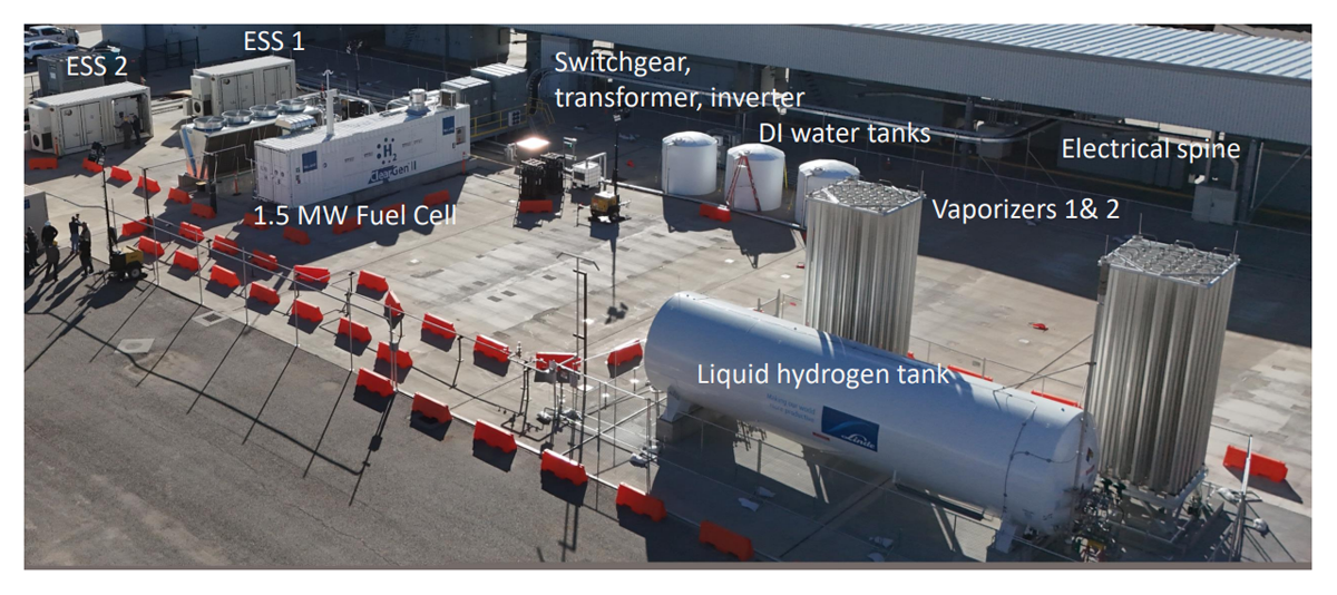
Figure 3
Site layout of the demonstration project showing bulk hydrogen storage, fuel cell, ESS, and electrical systems (Wang and Manda, 2024).
3. Results and Discussion
3.1 Safety and code compliance
Codes are generally considered to be the minimum safety requirements, while best practices or lessons learned are informed by other sources, like subject matter experts (SMEs), the Hydrogen Safety Panel, or information on websites like H2Tools (2024). In this demonstration, the EPC worked with NREL, the Hydrogen Safety Panel, and subsystem hydrogen experts from Ballard Power Systems and Caterpillar to support the development of a robust safety-focused design.
Coordination between the EPC company, subsystem designers, and hydrogen system experts was needed to streamline the design process, ensure that safety requirements were met, and that best practices were followed. NFPA 2, Hydrogen Technologies Code, and other standards have specific minimum requirements that must be complied with, such as setback distances between bulk hydrogen storage and other infrastructure (NFPA, 2023). In addition to setting the standard for safety, hydrogen safety codes and standards are valuable resources that can inform system design. Key high-level codes and standards for this demonstration were NFPA 2, CSA/ANSI FC1, CGA P-28, and NFPA 70.
3.2 Hydrogen safety plan
A hydrogen safety plan was developed and reviewed by the Hydrogen Safety Panel. The hydrogen safety plan includes critical safety documentation and provides a centralized reference location for all safety information for the project. This includes, but is not limited to, design specifications, hazard review documentation, risk analysis, procedures, and emergency response plans. The structure of a hydrogen safety plan provides a clear path for successful project completion and helps identify gaps in the deployment design and coordination.
The fuel cell deployment required detailed safety planning and expert knowledge of the system operation and maintenance. The project team started the safety planning process early and included SMEs throughout the project. According to H2Tools, the core members of the safety planning team should include safety professionals, project leader(s), operations manager, maintenance lead, workers, and subject matter experts (2024). Due to the novel aspect of the demonstration project, the Hydrogen Safety Panel, NREL, and external consultants all served as SMEs who supported the development of the safety argument.
Environmental, health, and safety (EH&S) points of contact (POCs) provided work authorization based on the completion and documentation of procedures, design, hazard review, and pre-startup safety review, which are all components of the safety planning process. With multi-entity projects—especially with larger companies—it is recommended that the EH&S POCs for the organizations that are the project lead and facility owner be involved in safety planning as early as possible. For the fuel cell demonstration, the project team initially focused on overcoming technical challenges and designing a safe system, while the policies and procedures related to operating the system were developed later in the project. This created two key challenges for the demonstration project. First, the EH&S POCs needed to be informed following the initial design phase. This led to the development and completion of project-specific policies and procedures for work authorization to be finalized just prior to system commissioning. Second, the project lead and facility owner were two different companies that required alignment of risk tolerance, policy, and safety documentation. Clear communication between companies was critical to ensure that the correct people were informed, and the operations were fully understood and authorized. Alignment and agreement were needed to determine elements such as training requirements, management of change, and emergency response plan, and other project safety documentation. The hydrogen safety plan was complete when the critical safety information and documentation were compiled and accessible to all project team members prior to introducing hydrogen to the facility.
3.3 Identification of safety vulnerabilities and risk reduction
As part of the safety planning for the demonstration project, the team completed two safety design reviews: the first using What-If analysis and the second using Hazard and Operability Analysis (HAZOP). The What-If analysis was conducted early in the project, prior to 30% design completion. This analysis allowed the team to evaluate the most significant hazards and identify relevant safeguards at an early stage of the demonstration project while the design could be modified.
Subsequently, an in-person safety review was completed by the project team using HAZOP analysis. Overall, the team found HAZOP to be an extremely valuable tool, identifying 87 safeguards that helped to mitigate the potential hazards. A total of 43 recommendations came from the HAZOP analysis and were subsequently managed to closure by the HAZOP team. Challenges associated with executing the HAZOP included: conducting HAZOP with key design details missing, conducting HAZOP with a large team, and the reliance on experience in the HAZOP process when used for novel systems or applications.
Since the HAZOP methodology relies on specific details of the system design and safety implementation, it was expected that conducting the HAZOP later in the project would be ideal for identifying and assessing the full breadth of possible hazards present. However, despite such scheduling, it was found during the HAZOP that some key details were missing, including instrument tag numbers, safety relief valve setpoints, instrumentation specifications, and piping specifications. The lack of key details resulted in more time being spent on design discussions and more post-HAZOP action items to be resolved. Also, missing details such as tag numbers made it difficult to properly reference specific equipment, valves, and instruments in the HAZOP report, leading to potential confusion weeks or months later. To mitigate the impact of design creep, the design for the hazard review was locked at a clear transition point, and the updated drawings were shared with the team. Ensuring that the design of the system is sufficiently established prior to the hazard review (regardless of when it falls in the project schedule) is recommended. Through the hazard review, changes were recommended and later implemented to improve the safe system design. This is a normal part of the hazard review process and was documented as part of the closeout of recommendations.
Due to this project involving multiple companies, a large number of people attended the hazard review. For a more efficient review, the number of people involved could have been reduced to key personnel. This would have optimized some aspects of the safety review process and kept the focus of the meeting on the task at hand. This was made more challenging due to the number of project partners involved in this demonstration. This was a first-of-its-kind demonstration that combined commercial and near-commercial systems in a novel way. Therefore, the safety review focused on how the different systems interface, rather than reviewing already established commercial system designs. This also meant that it was important to have all parties represented throughout the safety review. A narrowed list of key participants for the safety review includes the technology-specific subject matter experts, EH&S, and integration designers. Successful completion of the hazard review gave the demonstration a clear path to project success and documented whether the risk reduction methods that have been implemented are sufficient or if additional mitigation is needed.
Confirming that the risk mitigations claimed and recommended in the hazard review have been implemented as intended prior to the hazard, hydrogen—being introduced into the system—was tracked with recommendation closeout sheets. This provided documentation for how each recommendation from the safety review was incorporated in the design, or why that recommendation was not accepted, and if any other action was required. The physical implementation of the safeguards was then confirmed during the pre-startup safety review (PSSR).
Traditional Process Hazard Analysis (PHA) methods are qualitative methods of assessing and mitigating the hazards associated with an activity. The effectiveness of PHA tools such as HAZOP and Failure Mode and Effects Analysis (FMEA) depends in part on the experience of the team conducting the analysis. However, when working with new technologies or applying conventional technologies into new applications, there is often a lack of collective team experience, which risks the outcomes of these analyses. To provide a more quantitative understanding of the risk from the PEM fuel cell demonstration project, a contractor was hired to complete a quantitative risk analysis (QRA). Understanding the risk tolerance at the site and the failure mode assumptions are critical to the usability of a QRA. Contractors who have experience working with hydrogen QRAs should be able to recommend failure modes assumptions that are most important to understand the worst-case scenarios and the frequency or probability of that scenario occurring. This frequency number is critical as a scenario may present a significant hazard but the probability of that event occurring could be very low. Additionally, other controls or safeguards may be able to reduce the risk or probability to lower the hazard. This could include doing high-risk operations when there are fewer people at the facility, increasing the controlled area around equipment, minimizing the number of operators, or improving the blast resistance of control buildings and other areas where people will commonly be located, as was done for this demonstration. Sometimes, there are simple things that can be done to reduce the potential hazard associated with activities. The earlier this type of analysis is done, the sooner changes to the design and procedures can be implemented.
3.4 Permitting
The permitting process is heavily dependent on the location, scale, and nature of the hydrogen deployment. County and city officials play a major part in approving projects. In this case, the EPC coordinated directly with the local officials as a single point of contact. The local officials were notified of the upcoming hydrogen demonstration early in the project, and a meeting was held to share the project plan with the local officials. Complete design drawings were shared, along with a meeting to help the local officials better understand the location and scale of the demonstration project. The selected demonstration location was inside a data center facility with restricted public access in a sparsely populated industrial area. The permitting process for this demonstration project went smoothly with a few verifications following the initial proposal’s approval. These checks were specifically related to the design of the concrete foundations for the equipment. Throughout the construction phase of the project, the EPC coordinated with local officials to schedule the appropriate reviews and approvals required for operation.
3.5 Pre-startup safety review
The PSSR is a critical step in verifying that the equipment is installed as specified in the drawings and that safeguards accounted for in the hazard analysis have been correctly implemented. This happens before the primary hazard is introduced, which is hydrogen in this case. The PSSR included physical inspections in addition to in-person meetings to review the procedures, training, emergency response plans, and test plans. Once again, a key takeaway was to prioritize the procedures, training, emergency response plan, and test plan early in the development of the project. These documents are critical in a multi-entity project where agreement and alignment are needed by all stakeholders. Each entity needs to have a clear understanding of the scope of the work and what is authorized at the facility or with the equipment. Process documentation helps ensure that the right processes are in place to respond to an emergency and allow staff to complete their work safely with the right resources. Furthermore, the more finalized the system design build is—including the system documentation prior to the PSSR—the more thorough and effective a single review can be. Our team ended up completing multiple reviews to complete the PSSR checklist due to delays in the system integration. As the equipment reaches an operable state, there is a desire to start the equipment up. If you can have all the paperwork complete, this allows the PSSR to give startup approval and begin operation. Tight timelines can become challenging as even minor delays can affect the startup date and impact coordinated activities, such as hydrogen deliveries. Maintaining lines for clear communication and ensuring that all parties receive updated information and remain in agreement is crucial. Communication was a strength of the demonstration project team, especially as timelines became tight during the PSSR and commissioning. Leadership and the safety team did well to clearly communicate the status of the PSSR checklist and identify the critical path to startup.
3.6 Working with local AHJs and first responders
Prior to system startup, local first responders were invited onsite for training on the hazards associated with hydrogen and battery systems. They became familiar with the equipment, learned about best practices for emergency response, and asked questions about the deployment. The project team brought in an expert from the Hydrogen Safety Panel and a battery system SME from Caterpillar. This training and exchange of information was an effective way to engage the local community of first responders and share knowledge about battery and hydrogen systems. Liquid hydrogen systems are not very common yet, and the knowledge sharing was appreciated by the first responders. This type of first responder outreach is suggested for similar demonstration projects. It is an excellent way to help first responders be prepared and more comfortable responding to an emergency situation with novel systems.
3.7 Storage and handling of liquid hydrogen
The unique properties of hydrogen require proper component selection using hydrogen-compatible materials to ensure the safe deployment and longevity of the system. Sourcing components that are explicitly designed for hydrogen use has become easier but is not always possible. For the 1.5 MW project, the team worked with hydrogen system experts to review material compatibility and to assist with component selection. The hydrogen system experts were able to assist the designers in identifying valves and fittings that have been historically used for hydrogen service. The project team worked to develop a comprehensive system design, leveraging the Hydrogen Safety Panel and other SMEs, which incorporated safeguards and best industry practices for a safe deployment.
3.8 Integration with existing power systems
The integrated design should consider how commissioning, operation, and maintenance processes will be completed. For the demonstration, each subsystem was supplied with individual system processes that needed to be aligned for full system deployment. For example, understanding the commissioning process (e.g., pressure testing the system) will help the system designer ensure that lockout-tagout locations are available, a pressure testing source can be connected, and that all systems are protected from the pressure testing source and rated appropriately, thus allowing system commissioning to be completed in an optimized way. The demonstration project could have prioritized the development of integrated system procedures earlier in the design build process. An issue arose during commissioning when it was determined that the various purge procedures for the hydrogen systems were not aligned, leaving a segment of piping unpurged. In this case, the purge procedures for liquid hydrogen and for the downstream gas feed to the fuel cell were built by different teams, each with relevant experience in their particular system. It was assumed that by combining the two procedures, the complete system would be purged. However, each team aligned its procedures with standard company practice/experience. This presented a challenge in resolving the discrepancy as both teams had a strong preference to maintain a standard purge procedure. Ultimately, a solution was reached without a significant impact on the project timeline or system design, but it did require additional project team meetings to review and approve processes on short notice.
3.9 Construction
Equipment containing or transporting hydrogen was installed per the manufacturer’s specification and in accordance with the local and national codes and standards. In general, this was a standard construction operation. Equipment was lifted into position and integrated mechanically or electrically by the project partners or EPC.
When working with hydrogen—which tends to leak because of its small size—quality control is especially important. During the demonstration project, the weld inspection identified welds that did not pass. This highlights the value of a physical walkdown as part of the PSSR or other inspections to confirm that the expected equipment is installed and that the installation has been done correctly. The weld fixes consequently caused project delays and additional costs. More consequential process or safety issues were avoided, and the project team was able to respond and move forward. The project delays were in part due to challenges related to scheduling a weld inspector. Access to the data center was controlled and the authorized vendors were limited. These factors combined to cause the weld inspection timing to be late enough in the construction phase of the project that problem welds caused general project delays. An important lesson learned is to schedule quality control inspections shortly following completed work. This allows issues to be identified and resolved as efficiently as possible.
3.10 Commissioning
Following closeout of all PSSR open items identified as ‘critical,’ system commissioning began with the first liquid hydrogen fill. A key decision first proposed by the demonstration host and adopted by the project team was to limit the first fill of liquid hydrogen to days and times of low occupancy at the data center (i.e., outside normal working hours). This decision was taken as a risk mitigation strategy since liquid transfers are activities with an elevated risk profile. The first fill is at particularly heightened risk since the storage tank is warm (i.e., at ambient temperature), resulting in rapid vaporization, gas expansion, pressurization upon introduction of liquid, and increased venting of gaseous hydrogen.
As is commonly the case, the commissioning process included delays and beginning-of-life equipment failures. One lesson learned is to leave some extra time to resolve issues and bring the system online. Especially with novel system configurations, components may need to be repaired or replaced, and tuning may be needed to reach the desired performance.
3.11 Operation
System operation was carried out by Caterpillar and leveraged manufacturer expertise for the initial operation of the fuel cell system. Throughout testing, the team maintained communication and shared plans with relevant entities including site operations and site security. This included the starting of experiments and the duration of the operation. New equipment comes with unique noises and visuals that will be different from what the facilities previously experienced. Understanding when equipment will be running and the type of operation that is to be performed helps onsite personnel stay vigilant for out-of-normal situations that may arise.
One such situation occurred when a pressure safety valve (PSV) began leaking through. This caused the LH2 boiloff to be vented at an increased rate which tripped a parts per million, level alarm on the combustible gas detector in a nearby battery system enclosure. For the battery chemistry selected in the ESS systems, an early detection of thermal runaway is the off-gassing of hydrogen. Therefore, the ESS systems have hydrogen detectors with alarms activated by ppm levels of hydrogen.
Once notified of the alarm, the team responded, investigated, and determined the likely cause of the fault was LH2 boiloff, given that the combustible gas detector was working appropriately and the battery systems were healthy. The PSV was replaced, and the system returned to normal operation. The slight increase in hydrogen venting may have been caught more quickly if the team had a normal mode to compare to, but since the increased venting occurred following the initial tank fill, a normal boiloff rate for that tank and configuration had not been established. Understanding what normal operation looks like for a system is a key first step in being able to determine minor out-of-normal conditions.
Additionally, this alarm happened in the early morning. The hydrogen detector in the battery enclosure set off an audible and visual alarm at the site. Security personnel noticed the alarm and notified the appropriate Caterpillar contacts who were trained and authorized to investigate the issue. This event highlights the importance of proper education and awareness of site personnel, including those who are not directly involved in the demonstration, especially security personnel. The security team was well informed on what could be observed and how to respond to that observation. Site security had the proper lines of communication so that when an issue was identified, the correct person could be located and informed quickly. The safety planning and outreach done by the team allowed the site to be prepared to acknowledge a potential issue and respond appropriately.
There were other component faults during the demonstration, and the project team worked tirelessly to quickly and safely resolve these faults, collaborating with data center operations, data center safety, demonstration operations, and the demonstration safety team. Communication and agreement between project partners were critical for successful problem-solving and kept the demonstration moving forward. It is recommended to have some spare parts for key components and work closely with the suppliers to quickly resolve system faults. The team had the appropriate procedures in place to safely address and resolve these system faults.
3.12 Decommissioning
Decommissioning is a unique one-time action which generally does not fit into the standard operating procedures. This is a time to re-evaluate the associated hazard. Additionally, the personnel involved in decommissioning may be different than those involved with equipment operation. The project team worked diligently to ensure that the hydrogen hazard was removed, and all equipment was put into a safe state prior to handing off the equipment to the EPC for breakdown and removal. For the fuel cell system, the most important step in this process was the removal of excess hydrogen from the bulk storage tank. First, as much hydrogen as possible was consumed to create electricity. The remaining hydrogen was then vented following a safety evaluation by the data center and project safety teams. The venting was coordinated with the data center site operations and conducted by an experienced technician. These precautions helped ensure that a seemingly routine activity did not have an unanticipated impact on data center operations.
4. Conclusion
The fuel cell and battery system operated for over 150 MW-hours, successfully responding and matching load step profiles as requested by Microsoft, similar to verifying the performance of characteristics of a diesel genset. The fuel cell battery system was able to quickly ramp up and down to meet load requirements with the exhaust of the fuel cell being water. The integrated system met the Microsoft backup power performance metrics, successfully demonstrating the path for full-scale data center backup power using hydrogen. The technology demonstrated has broader applicability than just as a backup power solution, because it is a microgrid solution that can operate islanded or connected to the grid.
The success of this project was heavily dependent on the coordination of the multiple partners including Caterpillar, Ballard Power Systems, McKinstry, Microsoft, Linde, and NREL. There were many lessons learned throughout the design and deployment of the 1.5 MW fuel cell at a controlled data center. The project team was dedicated to a safe deployment, committing to the safety planning process. There were no OSHA recordables, Significant Injury or Fatality (SIF), or Potential Significant Injury or Fatality (PSIF) events across approximately 5,000 on-site person-hours.
Nomenclature
EH&S Environmental, Health and Safety
EPC Engineering, Procurement, and Construction
ESS Energy Storage System
HAZOP Hazard and Operability Study
HFTO Hydrogen and Fuel Cells Technologies Office
IEA International Energy Agency
LH2 Liquid Hydrogen
NFPA National Fire Protection Association
NREL National Renewable Energy Laboratory
OSHA Occupational Safety and Health Administration
PEMFC Proton Exchange Membrane Fuel Cell
POC Point of Contact
PSIF Potential Significant Injury or Fatality
PSSR Pre-Startup Safety Review
PSV Pressure Safety Valve
SIF Significant Injury or Fatality
SME Subject Matter Expert
Acknowledgements
Microsoft for providing a host site and requirements for the evaluation of the hydrogen data center concept.
This material is based upon work supported by the US Department of Energy’s Office of Energy Efficiency and Renewable Energy (EERE) under the Hydrogen and Fuel Cell Technologies Office, H2@Scale Initiative, Award Number DE-EE0009252.
This work was authored in part by NREL for the US Department of Energy (DOE), operated under Contract No. DE-AC36–08GO28308. Funding provided by the US Department of Energy Office of Energy Efficiency and Renewable Energy Hydrogen and Fuel Cell Technologies Office. The views expressed in the article do not necessarily represent the views of the DOE or the US Government. The US Government retains, and the publisher, by accepting the article for publication, acknowledges that the US Government retains a nonexclusive, paid-up, irrevocable, worldwide license to publish or reproduce the published form of this work, or allow others to do so, for US Government purposes.
Competing Interests
The authors have no competing interests to declare.