
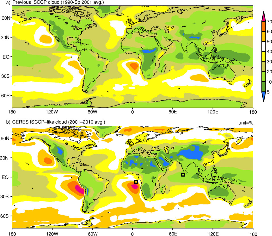
Fig. 1
Annual-mean low-level cloud fraction.
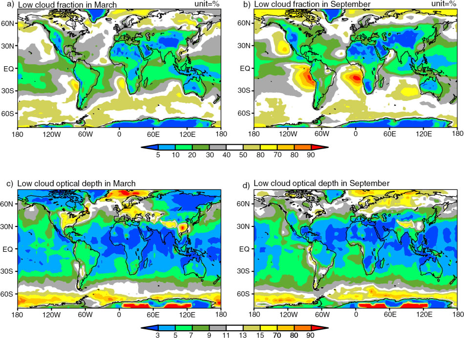
Fig. 2
CERES ISCCP-like cloud (2001–2010 average).
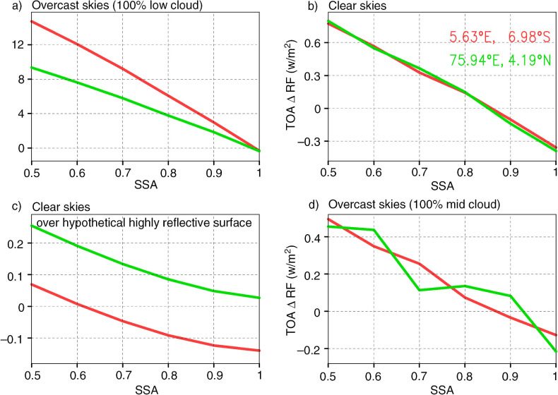
Fig. 3
Aerosol radiative forcing difference: ΔRF=RF2.5–3.5 km − RF0.0–1.0 km, where RF2.5–3.5 km refers to the forcing with aerosols between 2.5 and 3.5 km in height. The aerosol forcing is computed with the MACR model at two different locations: 5.63°E, 6.98°S and 75.94°E, 4.19°N (see Fig. 1b for the visual illustration of the locations), and the computed forcing represents the annual mean values at the TOA level. In (a), the overcast sky refers to a 100% cloud fraction by low-level cloud. The low cloud here is assumed to extend from 1.0 to 2.0 km in height. In (c), the surface is assumed to be land with an albedo of 0.9. In (d), the overcast sky refers to a 100% cloud fraction by mid-level cloud, which is set to extend from 4.0 to 6.0 km in height.
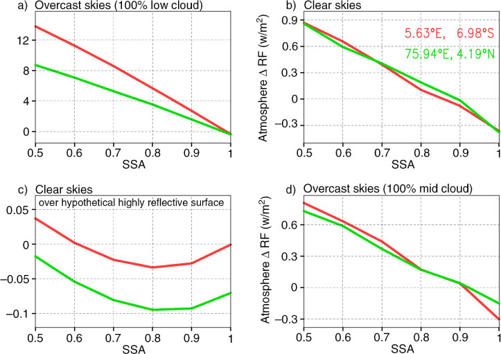
Fig. 4
Same as Fig. 3 except for the aerosol forcing in the atmosphere.
Table 1. The global sum of annual mean ∣ΔRF∣=∣RFupper-RFlower∣
[i] See Fig. 3 for the detailed definition of ΔRF.
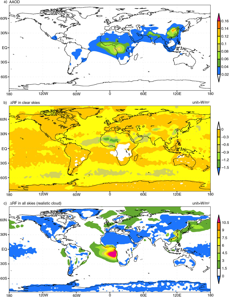
Fig. 5
AAOD (Absorption Aerosol Optical Depth) at 550 nm in (a). Aerosol radiative forcing difference: ΔRF=RF2.5–3.0 km − RF0.0–0.5 km, in (b) and (c). The aerosol forcing is computed with the MACR model, and the computed forcing represents the 2001–2010 mean values at the TOA level. Realistic 3D clouds from satellite observations are used in (c). These clouds are removed in (b).
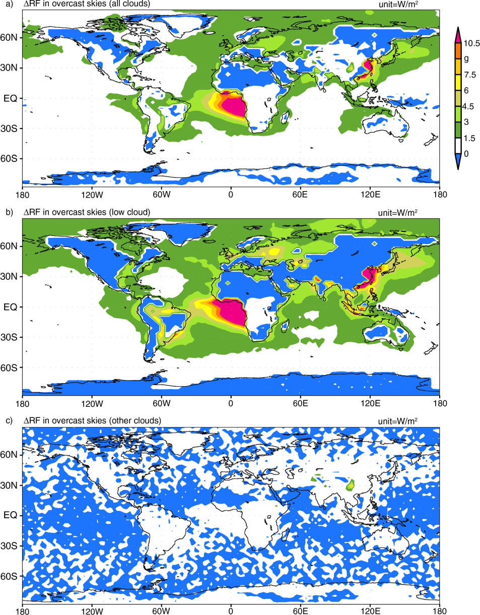
Fig. 6
Aerosol radiative forcing difference: ΔRF=RF2.5–3.0 km − RF0.0–0.5 km. Realistic 3D clouds as in Fig. 5c are expanded in fraction to have a 100% cloud fraction collectively in a). In b), the fraction of low cloud is set to 100% while other clouds are zeroed. In c), the low cloud is zeroed and other clouds are expanded in fraction to have a 100% cloud fraction collectively.