Table 1. Summary of acronyms and key clarifications
Fig. 1.
Three particle shapes used in this study: (a) black carbon (BC) aggregate generated by the cluster–cluster diffusion-limited aggregation algorithm with a fractal prefactor of 1.6, and fractal dimension (D f ) of 1.8; (b) BC aggregate with D f =2.4; and (c) BC sphere coated by scattering material. Black carbon in all of (a)–(c) has the same equivalent volume diameter.
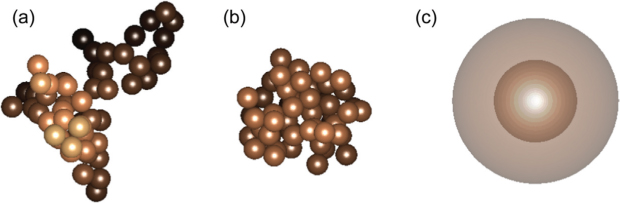
Table 2. Calculated optical properties of uncoated black carbon (BC) at 550 nm, as averaged over a realistic size distribution. All the cases in this table have the same amount of BC volume. Black carbon refractive index is 1.8–0.71i. BSCA refers to backscattering
[i] ASY, asymmetry parameter.
Table 3. Same as in Table 2 except for different K f
[i] ASY, asymmetry parameter.
Fig. 2.
GSD and CMD changes as the black carbon (BC) population is coated with increasing shells. With no shell, the CMD of BC is set to 122 nm. Shells increase the CMD of the particles. When the shell size increases linearly (i.e., equal shell size for all the BC cores), GSD declines with shell size. When we increase the ratio of shell to core (i.e., equal ratio for all the particles) to increase shell size, GSD remains unchanged.
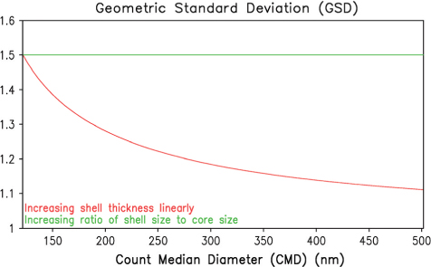
Fig. 3.
(a) Ratio of absorption/backscattering cross-section for coated black carbon (BC) to that for uncoated BC + scattering aerosol, at 550 nm. (b) ‘New particle creation scenario’ means that scattering shells create new scattering aerosols in the absence of BC. (c) ‘Existing particle expansion scenario’ is that scattering shells expand existing scattering aerosols instead of creating new particles. Red lines denote the coating experiment where the shells increase linearly; see Fig. 2 to understand ‘linearly’ and ‘ratio’. Uncoated BC optical properties are calculated in two ways: Assuming cluster structure of D f =1.8 (dashed line) and spherical shape (solid line) of BC population. The results in the hatched region are not very accurate as the Mie scattering core–shell model does not work well in this range. The shell refractive index is 1.465 + i0.0, as in Moffet and Prather (2009).
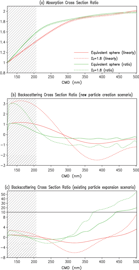
Fig. 4.
Same as Fig. 3, except for the ratio of absorption/backscattering cross-section for coated black carbon (BC) (i.e., BC + scattering material) to that for uncoated BC at 550 nm.
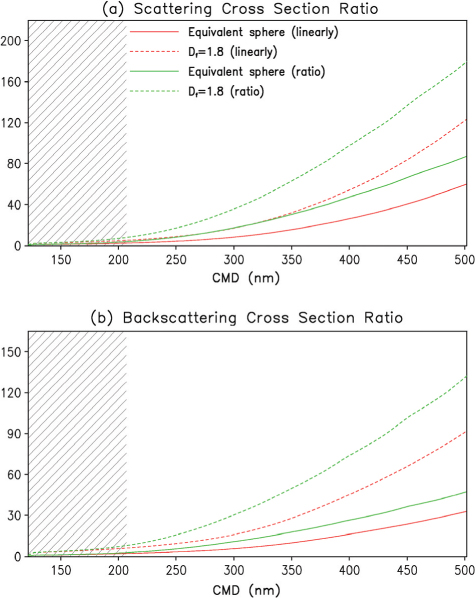
Fig. 5.
Absorption Angstrom Exponent (AAE) of uncoated black carbon (BC) and coated BC. Closed symbols denote AAE of uncoated BC, when BC is treated as spheres (circle), aggregates with D f =2.4 (triangle) and aggregates with D f =1.8 (square). Coated BC has two ways to increase shells; see Fig. 2 for details. The results in the hatched region are not very accurate as the Mie scattering core–shell model does not work well in this range.
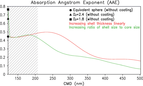
Fig. 6.
Black carbon (BC) aerosol optical depth (AOD) and BC forcing, when BC is all externally mixed with other aerosols.
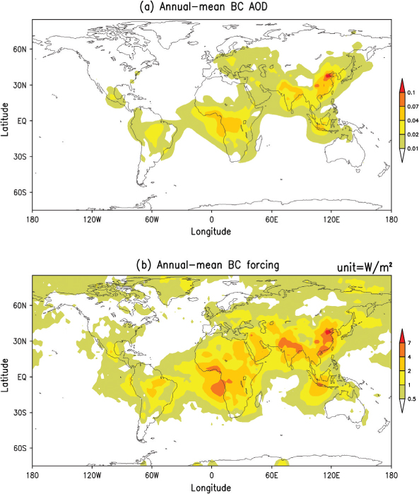
Table 4. Simulated globally averaged annual-mean black carbon (BC) forcing (anthropogenic + natural)
[i] TOA, top of the atmosphere.
Fig. 7.
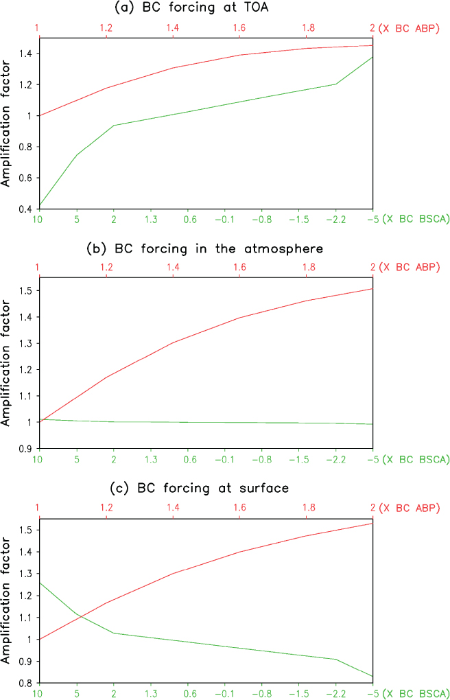
Ratio of black carbon (BC) forcing for coated BC to that for uncoated BC: (a) at the top of the atmosphere (TOA), (b) in the atmosphere and (c) at the surface. Black carbon forcing for coated BC here means the forcing for coated BC minus the forcing for scattering aerosols; see Section 1 for clarification. In this definition, coating always increases BC absorption but may decrease BC backscattering. The experiments here demonstrate the separate effects of BC absorption increase and BC backscattering change.