
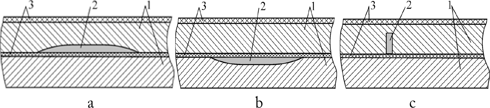
Fig. 1.
Hard-to-inspect double-layer ASs with uniform CD situated on the bottom surface of the first (top) layer (a) or top surface of the second layer (b); and local CD (pitting) situated on the bottom surface of the first (top) layer (c): 1 – skin; 2 – CD; 3 – dielectric coatings or sealants.
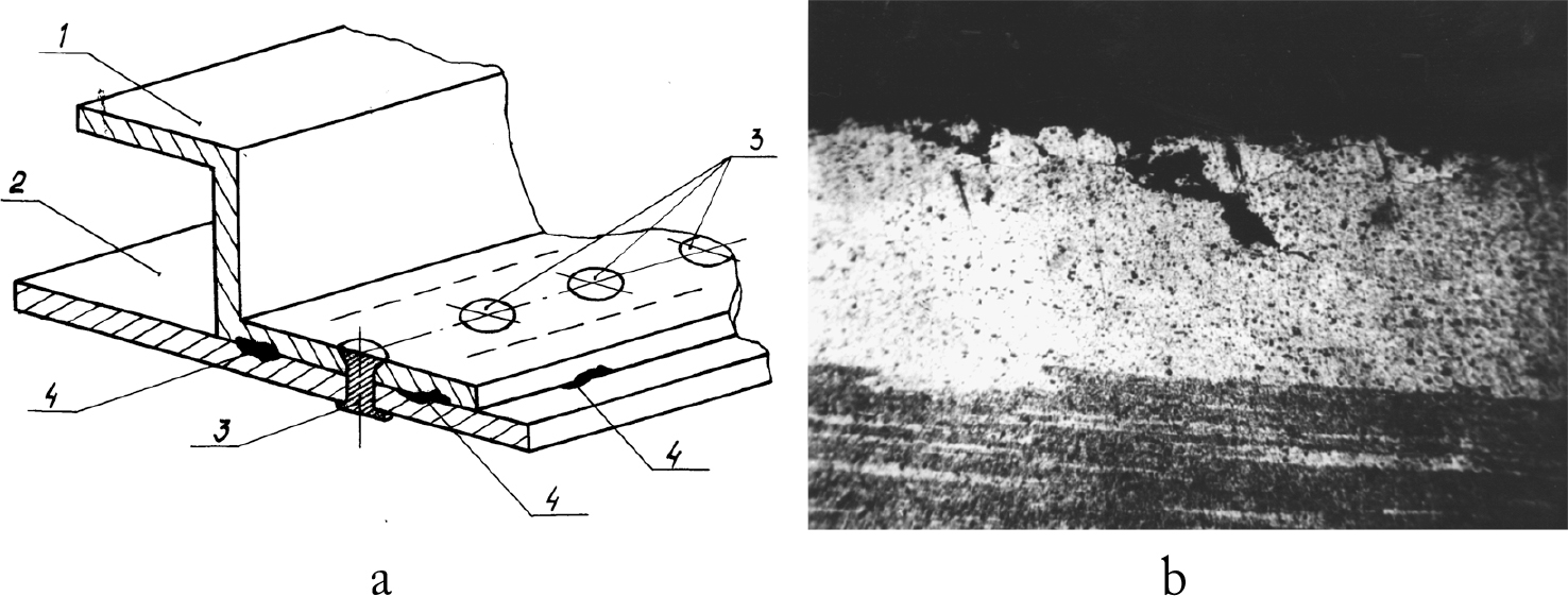
Fig. 2.
Evaluated stringer-skin type joints with local CDs, where 1 – stringer; 2 – cladding; 3 – rivets; 4 – local CD (a) and detected local CD (b)
Table 1.
Parameters of investigated EC probes
| EC probe type | DECP, mm | Df, mm | We | Ws | Le , μH | Ls , mH |
|---|---|---|---|---|---|---|
| MDF 0601 | 6.0 | 1.0 | 185 | 360 | 320 | 1.2 |
| MDF 0801 | 8.0 | 1.85 | 215 | 416 | 940 | 3.7 |
Table 2.
Detectability of local CDs using MDF 0801 and MDF 0601 EC probes
| EC probe type | MDF 0801 | MDF 0601 | MDF 0801 | MDF 0601 | MDF 0801 | MDF 0601 | MDF 0801 | MDF 0601 | MDF 0801 | MDF 0601 | MDF 0801 | MDF 0601 |
|---|---|---|---|---|---|---|---|---|---|---|---|---|
| hr, mm | 0.5 | 1.0 | 1.5 | 2.0 | 2.5 | 3.0 | ||||||
| Dlc, mm | ||||||||||||
| 2.0 | + | + | + | + | + | + | + | - | + | - | - | - |
| 3.0 | + | + | + | + | + | + | + | - | + | - | - | - |
| 5.0 | + | + | + | + | + | + | + | ± | + | - | ± | - |
Table 3.
Detectability of local CD situated in the second layer during inspection through the upper 1.6 mm thick skin using MDF 0801 and MDF 0601 type EC probes
| EC probe type | MDF 0801 | MDF 0601 | MDF 0801 | MDF 0601 | MDF 0801 | MDF 0601 | MDF 0801 | MDF 0601 | MDF 0801 | MDF 0601 | MDF 0801 | MDF 0601 |
|---|---|---|---|---|---|---|---|---|---|---|---|---|
| Tlc, mm | 3.0 | 2.5 | 2.0 | 1.5 | 1.0 | 0.5 | ||||||
| Dlc , mm | ||||||||||||
| 2.0 | + | + | + | + | + | + | + | + | + | + | + | + |
| 3.0 | + | + | + | + | + | + | + | + | + | + | + | + |
| 5.0 | + | + | + | + | + | + | + | + | + | + | + | + |
Table 4.
Detectability of local CD situated in the second layer during inspection through the upper 2.2 mm thick skin using MDF 0801 and MDF 0601 type EC probes
| EC probe type | MDF 0801 | MDF 0601 | MDF 0801 | MDF 0601 | MDF 0801 | MDF 0601 | MDF 0801 | MDF 0601 | MDF 0801 | MDF 0601 | MDF 0801 | MDF 0601 |
|---|---|---|---|---|---|---|---|---|---|---|---|---|
| Tlc, mm | 3.0 | 2.5 | 2.0 | 1.5 | 1.0 | 0.5 | ||||||
| Dlc , mm | ||||||||||||
| 2.0 | + | ± | + | ± | + | ± | + | ± | + | - | + | - |
| 3.0 | + | + | + | + | + | + | + | + | + | ± | + | - |
| 5.0 | + | + | + | + | + | + | + | + | + | ± | + | - |
Table 5.
Detectability of local CD situated in the second layer during inspection through the upper 2.8 mm thick skin using MDF 0801 and MDF 0601 type EC probes
| EC probe type | MDF 0801 | MDF 0601 | MDF 0801 | MDF 0601 | MDF 0801 | MDF 0601 | MDF 0801 | MDF 0601 | MDF 0801 | MDF 0601 | MDF 0801 | MDF 0601 |
|---|---|---|---|---|---|---|---|---|---|---|---|---|
| Tlc, mm | 3.0 | 2.5 | 2.0 | 1.5 | 1.0 | 0.5 | ||||||
| Dlc , mm | ||||||||||||
| 2.0 | + | - | + | - | + | - | + | - | + | - | - | - |
| 3.0 | + | ± | + | - | + | - | + | - | + | - | ± | - |
| 5.0 | + | + | + | ± | + | ± | + | ± | + | - | ± | - |
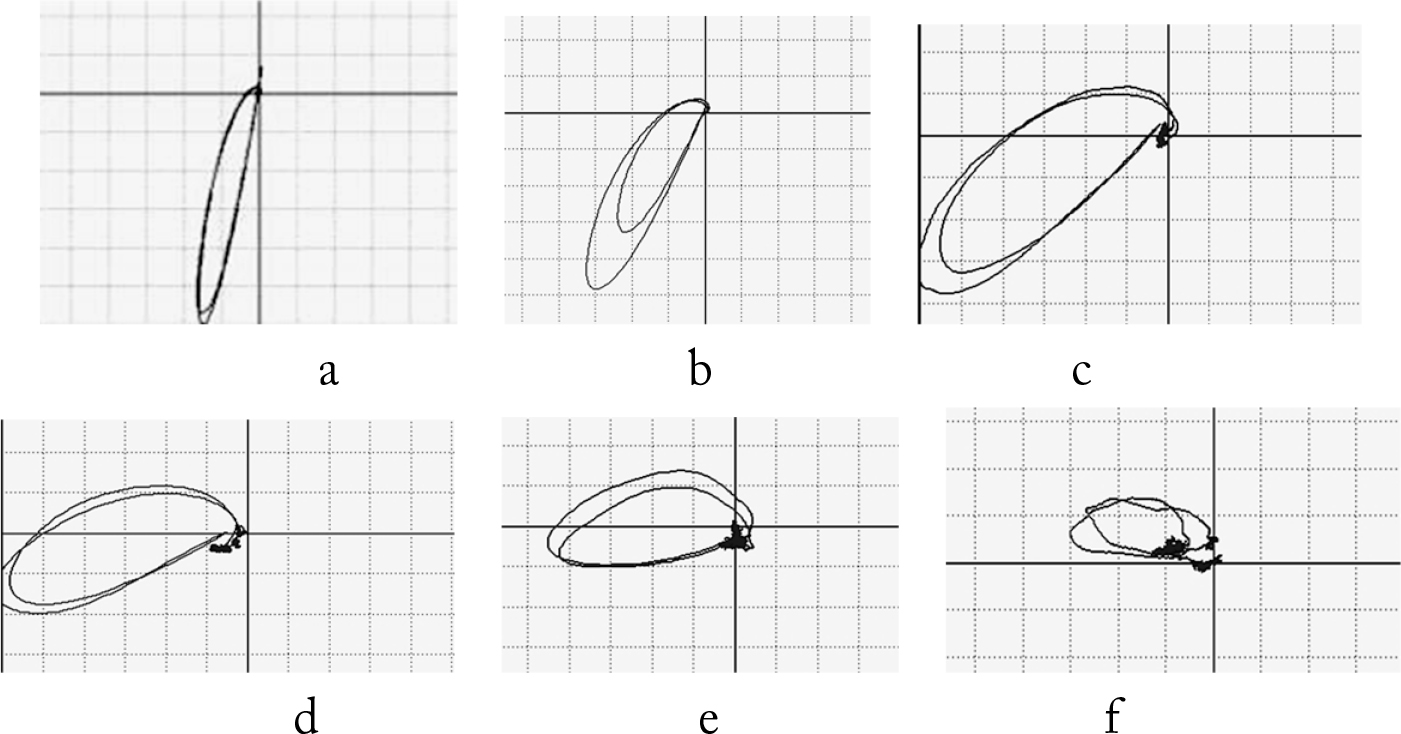
Fig. 3.
EC signal in the complex plane (hodographs) created by 2.0 mm diameter local CD for surface location (a), and created by subsurface 2.0 mm diameter local CDs with residual thicknesses 0.5 mm (b); 1.0 mm (c); 1.5 mm (d); 2.0 mm (e); and 2.5 mm (f)
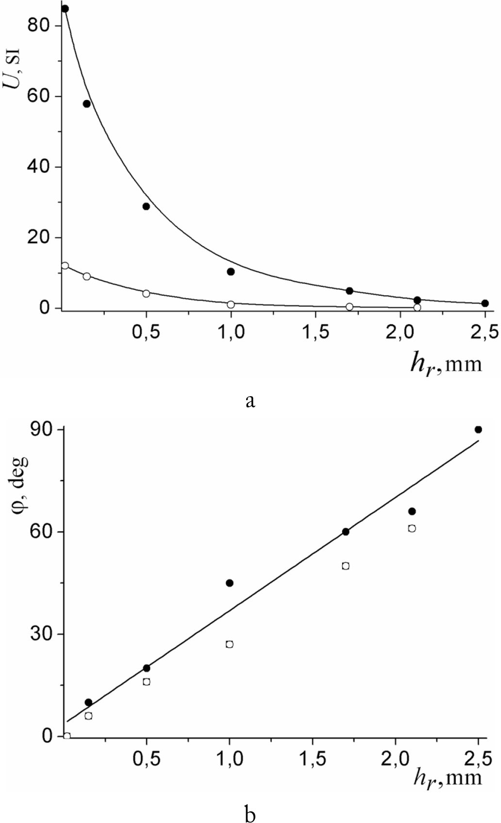
Fig. 4.
Dependences of EC signal amplitude U (a) and phase angle φ (b) created by local CD on the residual thickness hr for EC probes of MDF 0601 (●) and MDF 0801 (○) types