
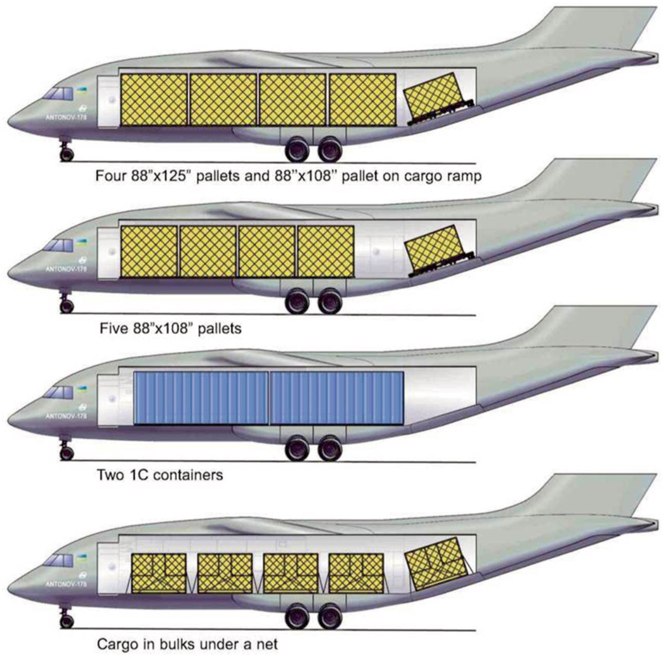
Figure 1.
Options for the loads arrangement in the cargo compartment for transportation in containers and on standard aircraft pallets.
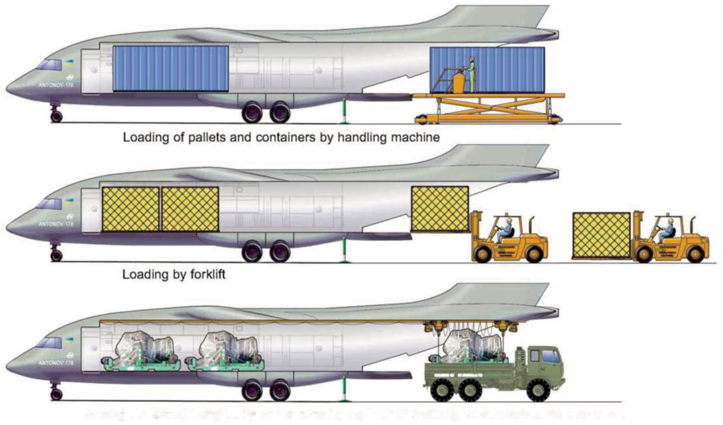
Figure 2.
Schemes for loading cargo in containers and on standard aircraft pallets.
Table 1.
Transported loads nomenclature.
| Transported loads | Quantity | Weight, tones. |
|---|---|---|
| Soldiers, people | 90 | 10.8 |
| Paratroopers, people | 70 | 8.3 |
| Injured on stretchers + on chairs, people | 48 + 15 | 6.0 |
| Containers, inch (m): | ||
| M1 96″ × 96″ × 125″ (2,438 × 2,438 × 3,175) | 4 | 18.0 |
| M2 96″ × 96″ × 238.5″ (2,438 × 2,438 × 6,058) | 2 | 18.0 |
| M3 88″ × 96″ × 125″ (2,235 × 2,438 × 3,175) | 4 | 18.0 |
| ID 96″ × 96″ × 117.8″ (2,438 × 2,438 × 2,991) | 2 | 18.0 |
| 1C 96″ × 96″ × 238.5″ (2,438 × 2,438 × 6,058) | 2 | 18.0 |
| Pallets, inch (m): | ||
| 88″ × 108″ (2,235 × 2,743) | 5 | 18.0 |
| 88″ × 108″ (2,235 × 3,175) | 4 | 18.0 |
| 88″ × 108″ (2,438 × 3,175) | 4 | 18.0 |
| 88″ × 108″ (2,438 × 6,058) | 2 | 18.0 |
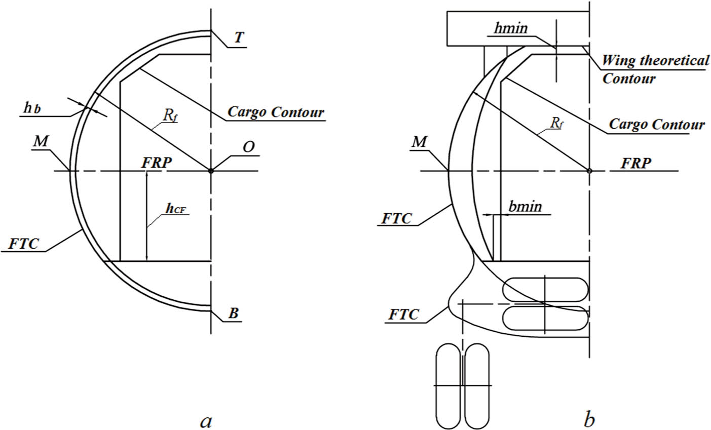
Figure 3.
Sections of the cargo compartment in the zone of the fuselage single curvature
(a – regular fuselage cross-section; b – fuselage cross section in the wing area).
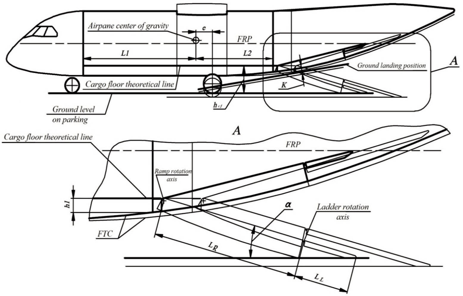
Figure 4.
Scheme for determining the length of the sloped floor and the nodes of the ramp hinge. FRP, fuselage reference plane.
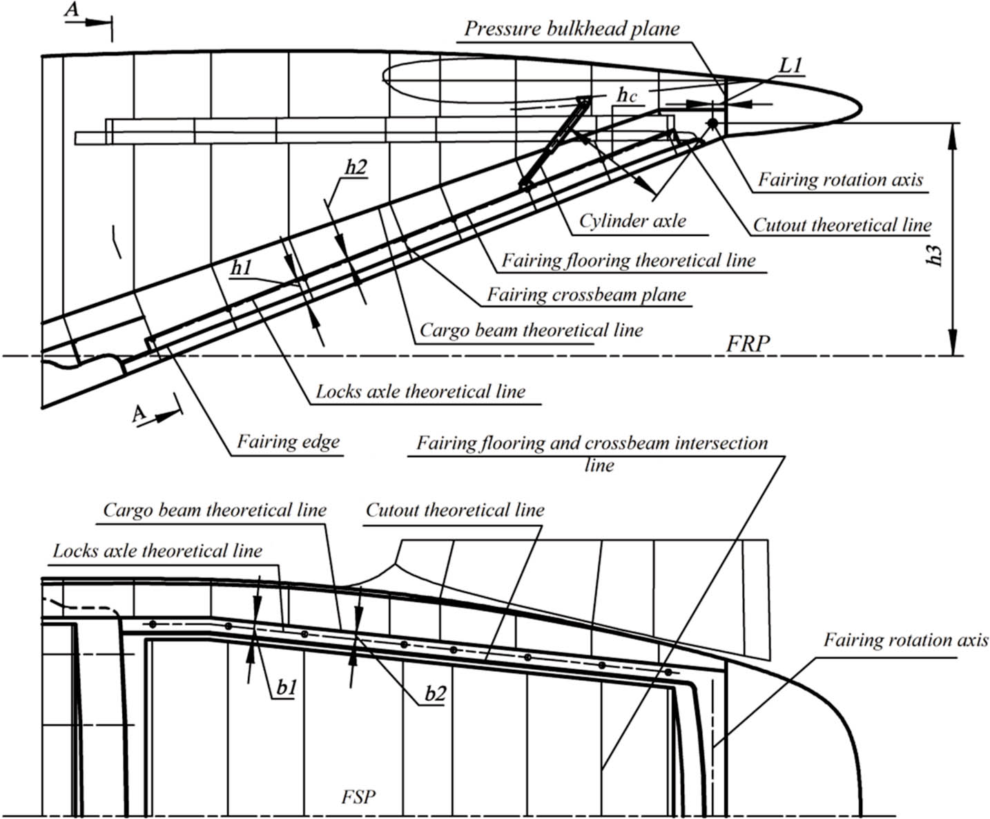
Figure 5.
General view of a pressurisated fairing compartment. FRP, fuselage reference plane; FSP, fuselage symmetry plane.
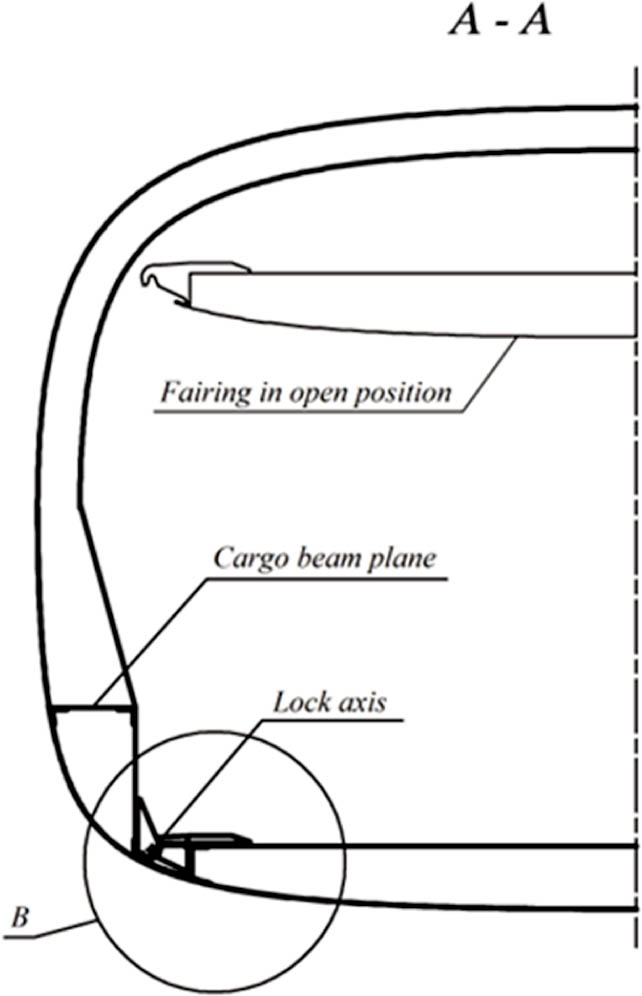
Figure 6.
Sectional view of a pressurisated fairing compartment.
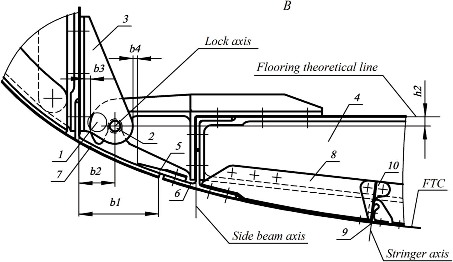
Figure 7.
Fairing closed position lock. FTC, fuselage theoretical contour.
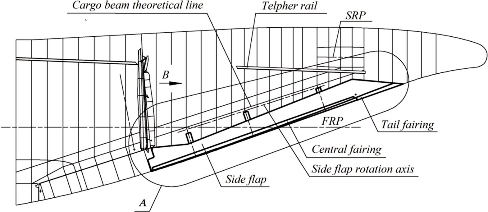
Figure 8.
Main view of fuselage tail part with non-pressurisated fairing compartment. FRP, fuselage reference plane; SRP, stabiliser reference plane.
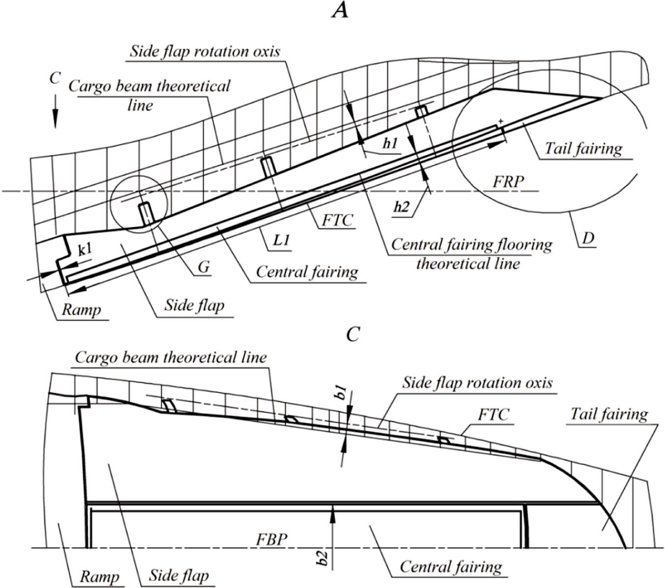
Figure 9.
Main and bottom view of non-pressurisated fairing compartment. FRP, fuselage reference plane; FTC, fuselage theoretical contour; FSP, fuselage symmetry plane.
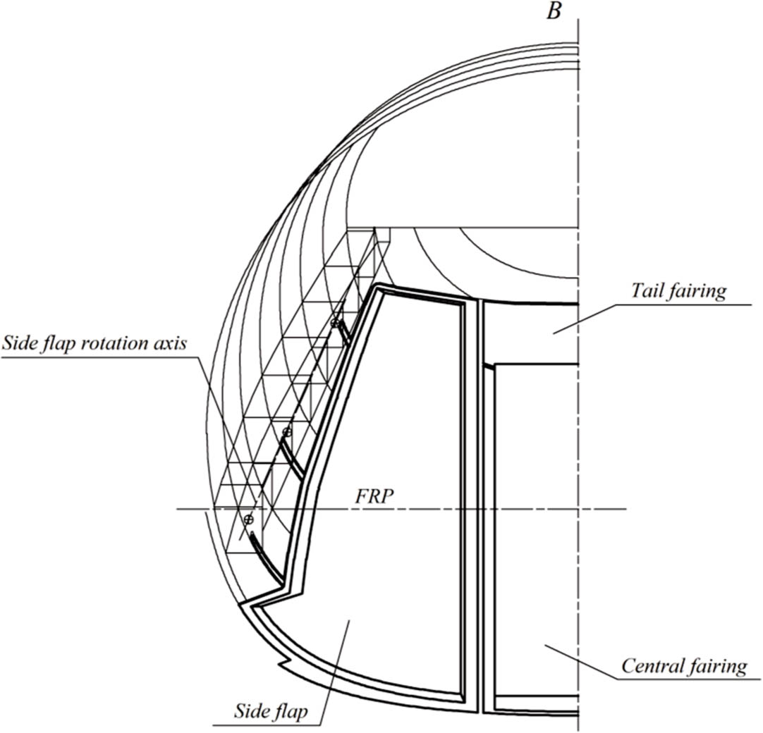
Figure 10.
Sectional view of non-pressurisated fairing compartment. FRP, fuselage reference plane.
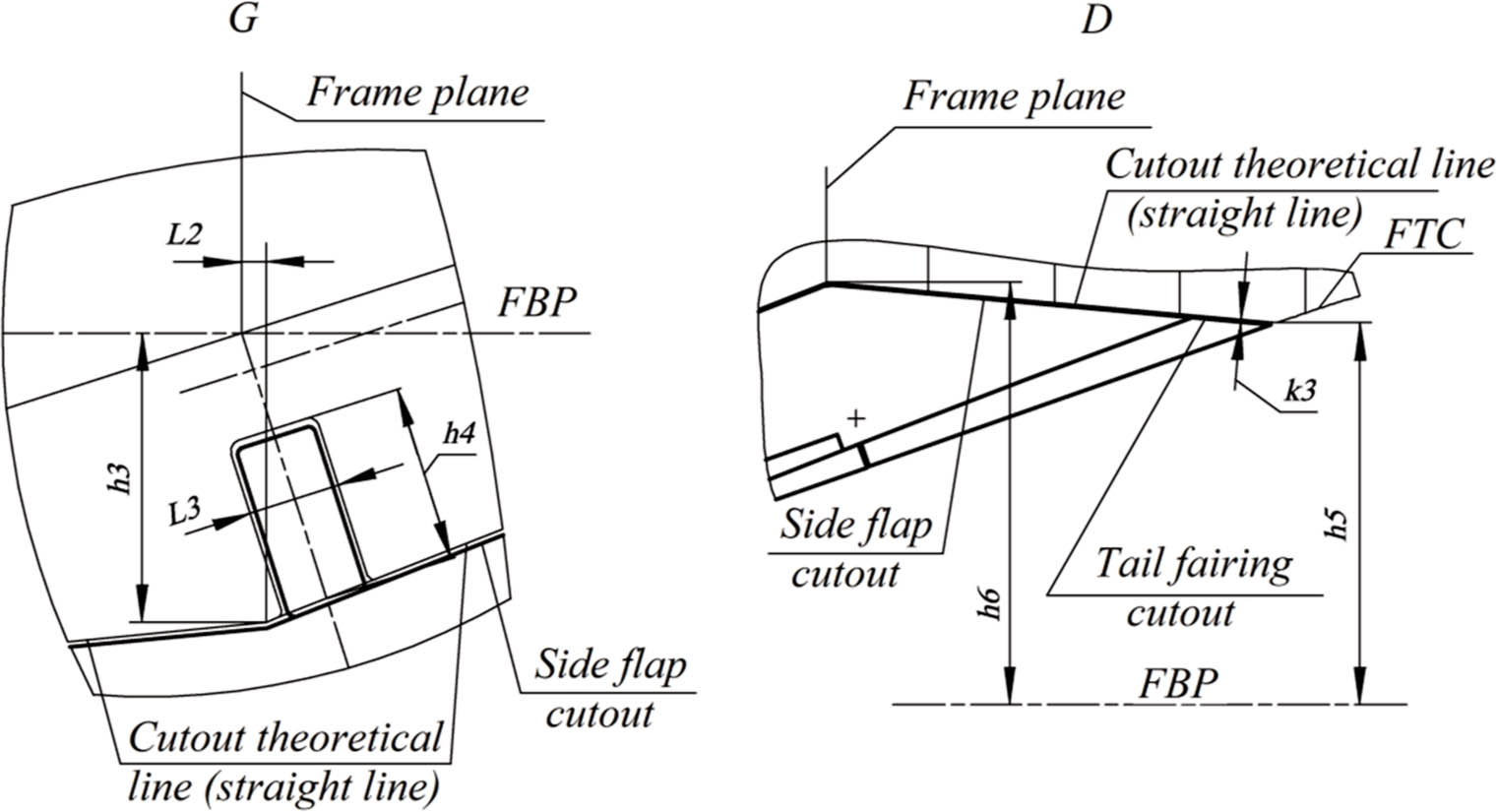
Figure 11.
Profiling of the cutouts for the side flaps hinge nodes and determination of the cut of the fairing compartment tail section. FRP, fuselage reference plane; FTC, fuselage theoretical contour.
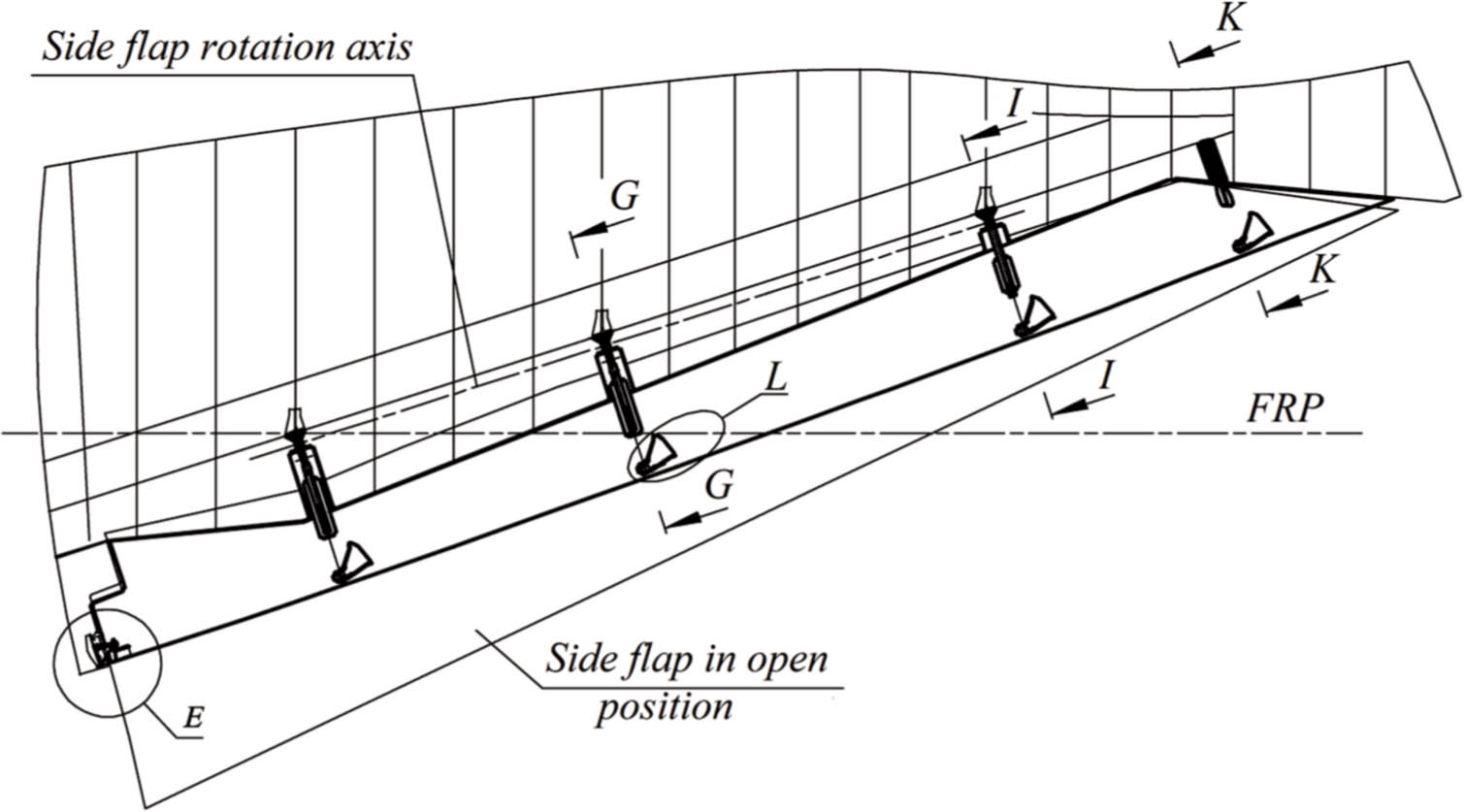
Figure 12.
Side flaps catchers location. FRP, fuselage reference plane.
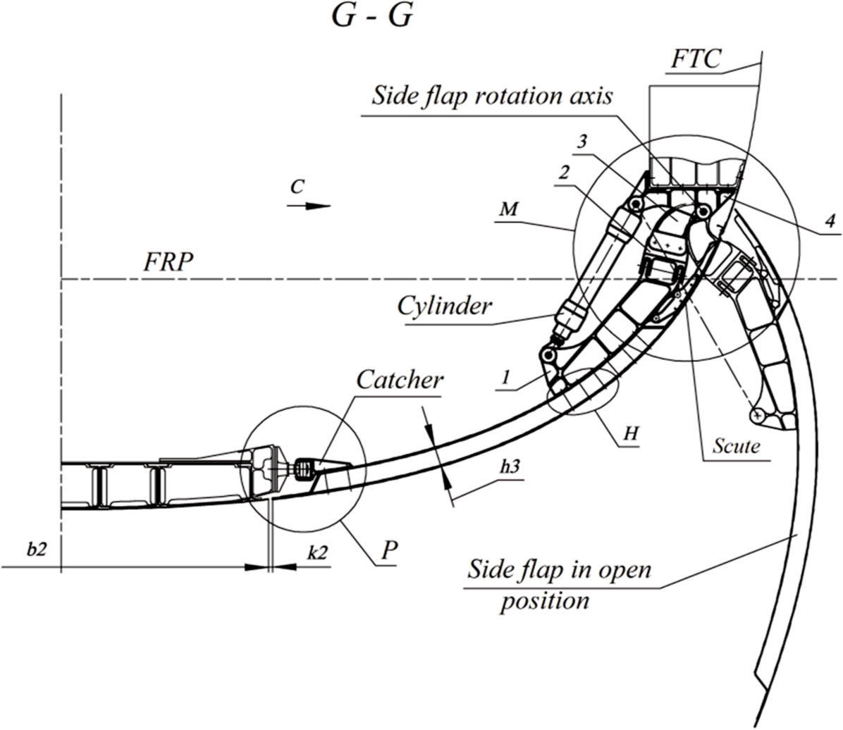
Figure 13.
Sectional view of the side flaps. FRP, fuselage reference plane; FTC, fuselage theoretical contour.
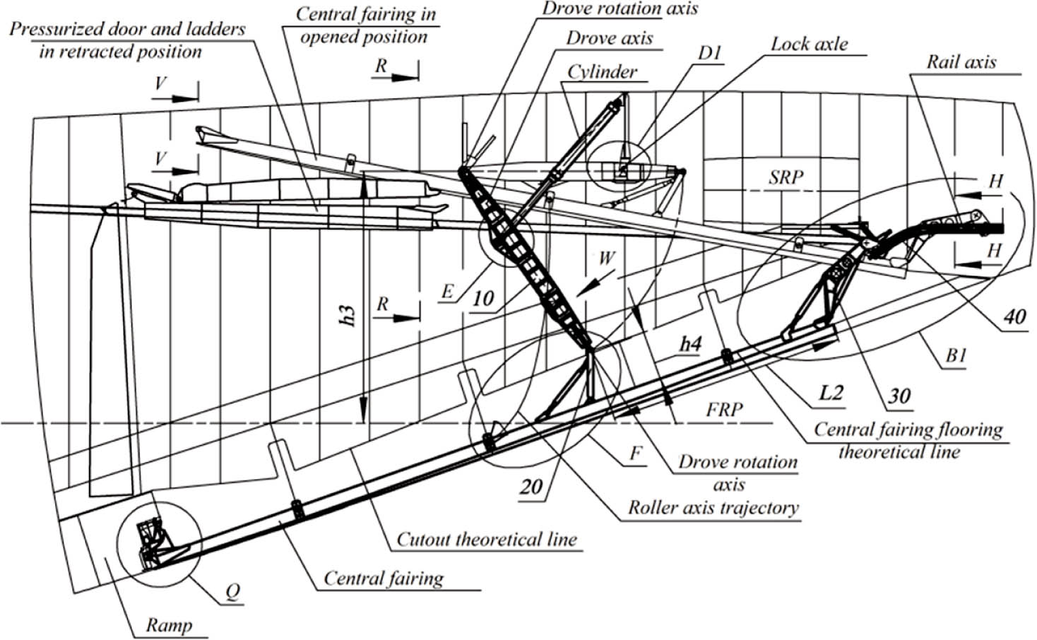
Figure 14.
Central fairing controlling. (10 – carrier; 20 – carrier bracket; 30 – rear hitch assembly; 40 – rail.) FRP, fuselage reference plane; SRP, stabiliser reference plane.
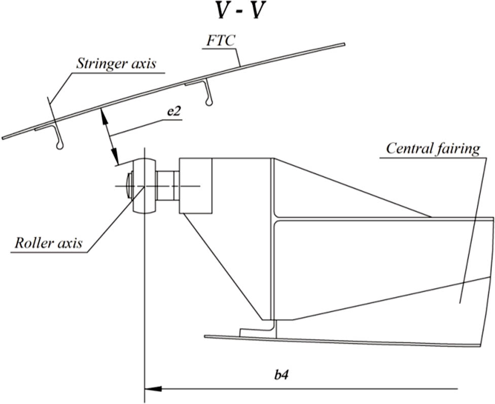
Figure 15.
Central fairing in the open position. FTC, fuselage theoretical contour.
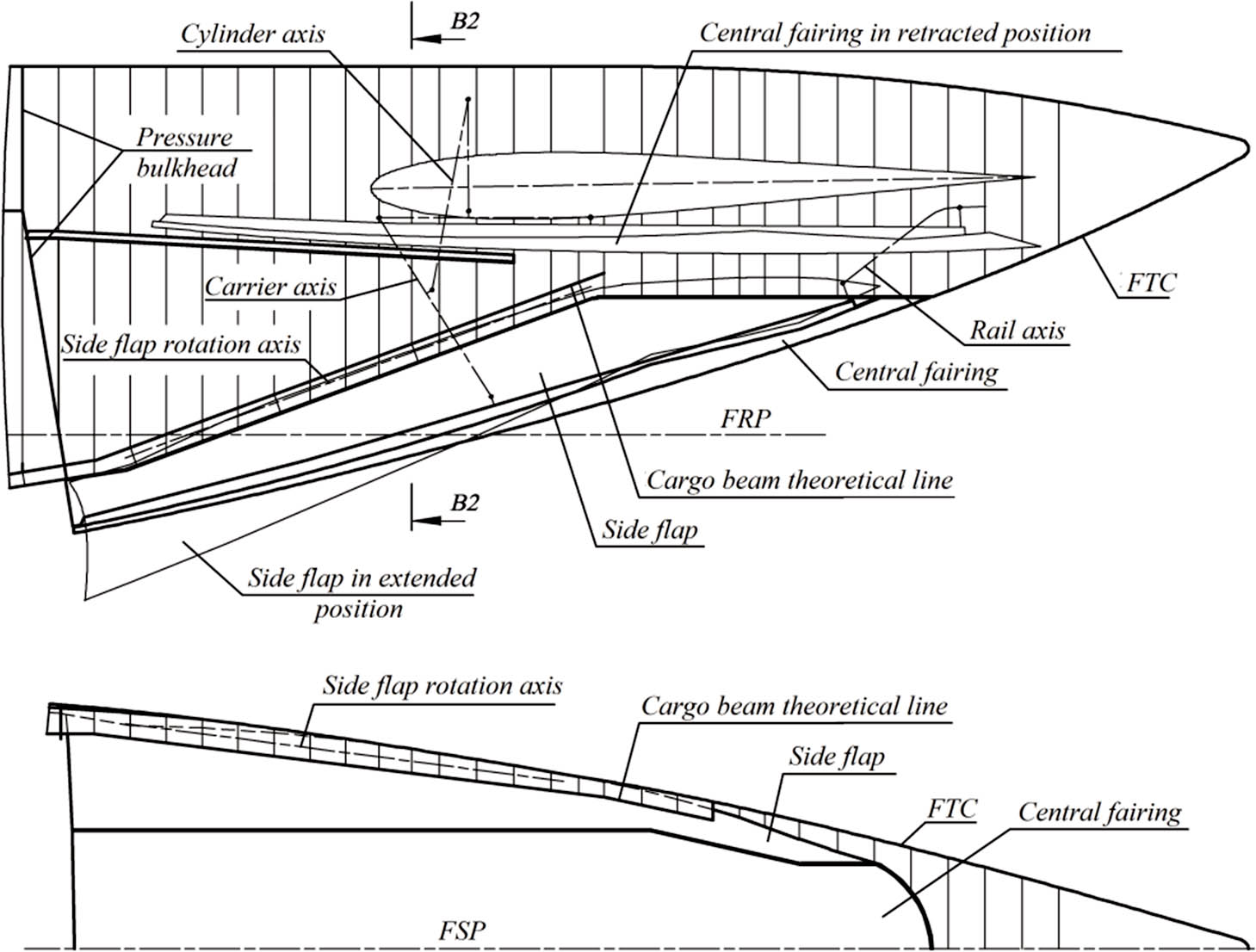
Figure 16.
Fairing compartment of a double-deck fuselage. FRP, fuselage reference plane; FTC, fuselage theoretical contour.
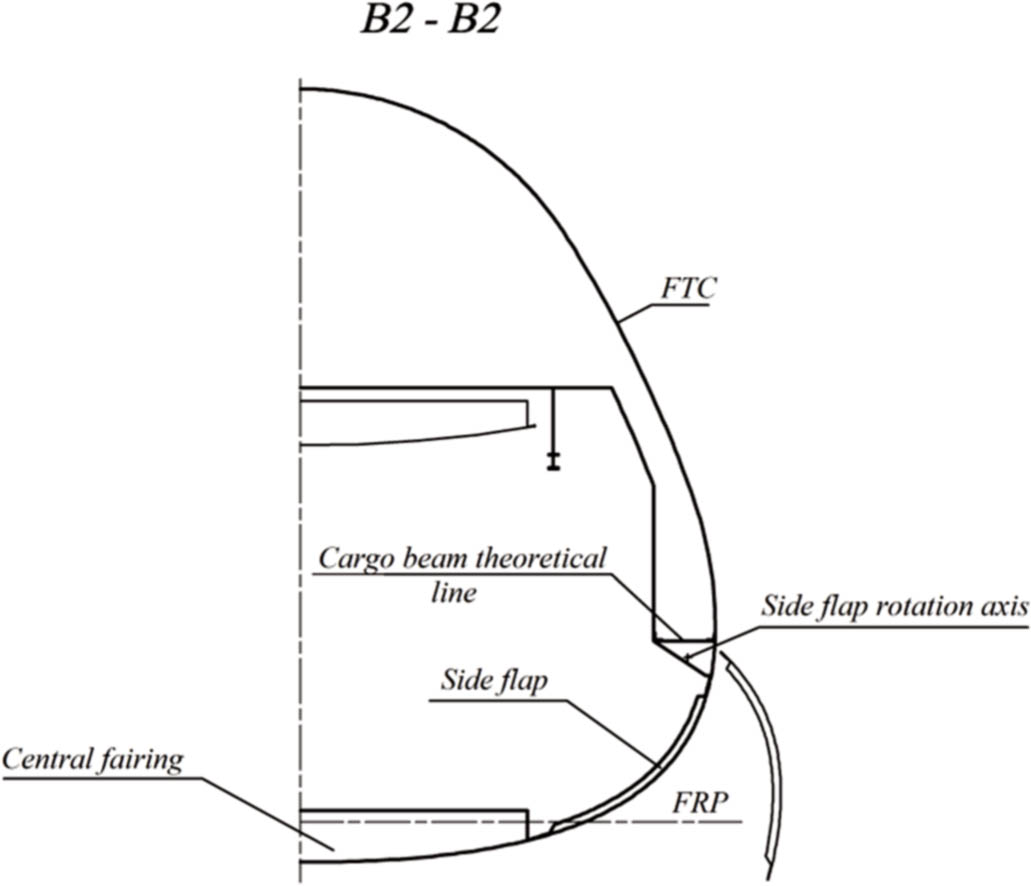
Figure 17.
Sectional view of the double-deck fuselage fairing compartment.
FRP, fuselage reference plane; FTC, fuselage theoretical contour.
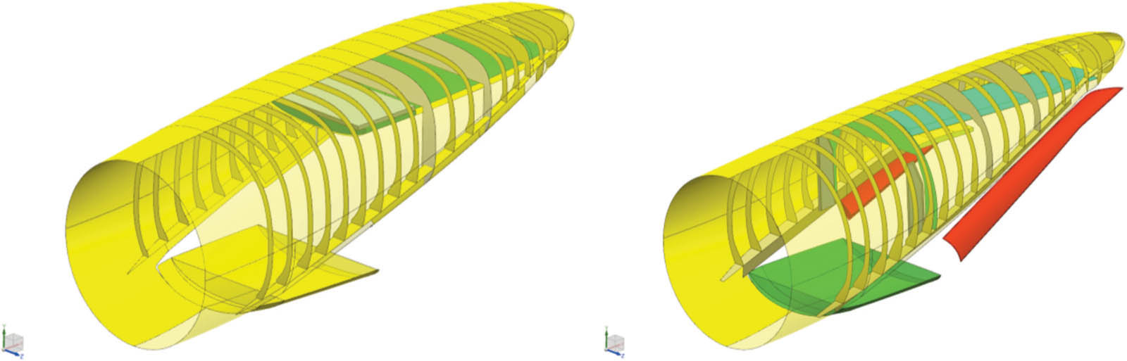
Figure 18.
Cargo door pressurised and non-pressurised fairing compartment.