
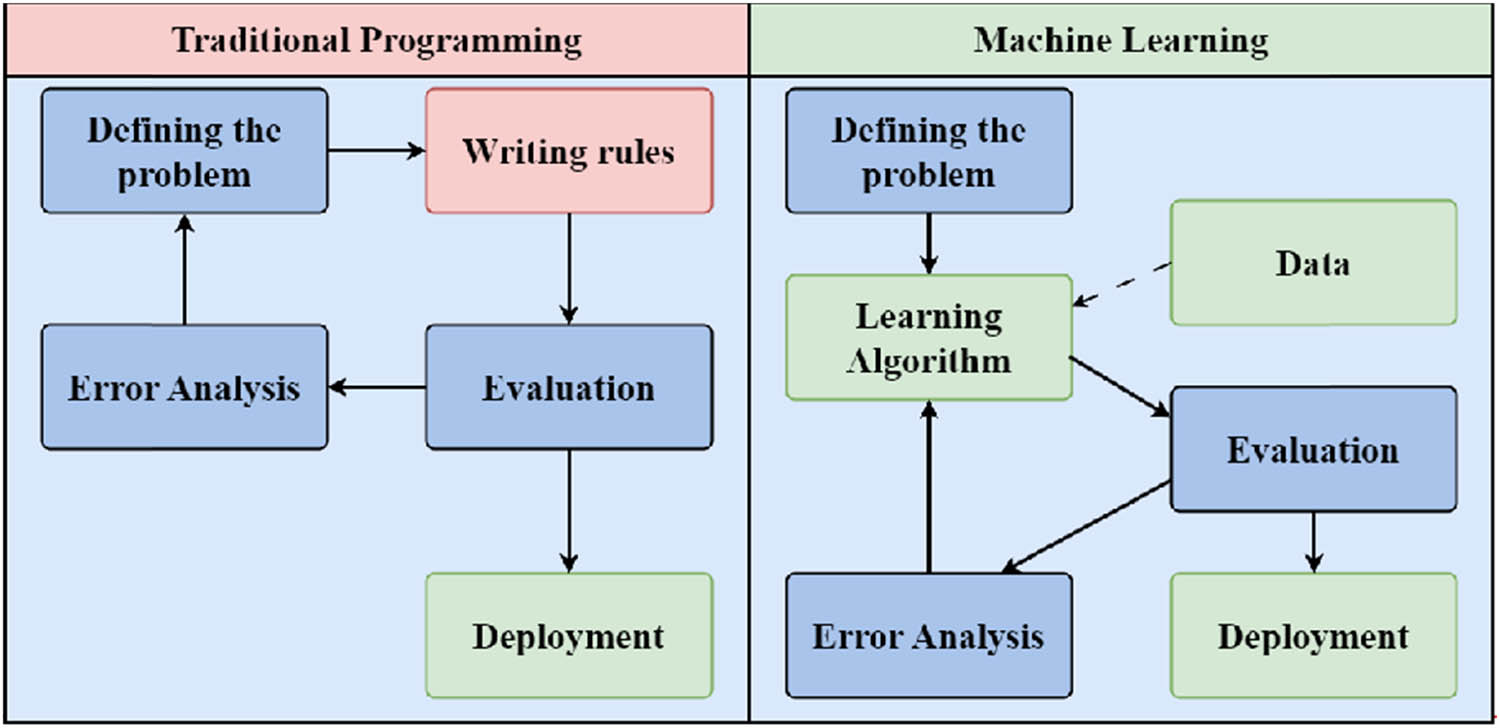
Figure 1
Comparative diagram of creating an algorithm based on traditional programming and ML.
Source: Author’s contribution; adapted from Géron [1].
Table 1
Overview of ML algorithm families.
| Algorithm family | Selected algorithms | Description |
|---|---|---|
| Linear methods | Linear Regression | Introduced as early as the nineteenth century by Francis Galton, formalized as a statistical model by Karl Pearson at the beginning of the twentieth century |
| Logistic Regression | Developed by David Cox in the 1950s | |
| Ridge Regression | Introduced in the 1970s by Hoerl and Kennard | |
| Lasso Regression | Developed by Robert Tibshirani in 1996 | |
| Decision trees and variants | Decision Trees | Developed from the 1960s, formally defined in the 1980s by Leo Breiman (CART algorithm – Classification and Regression Trees) |
| Random Forests | Introduced by Leo Breiman in 2001 as a combination of multiple decision trees to improve model accuracy | |
| Support vector machines | Support vector machines | Developed in the 1990s by Vladimir Vapnik and his collaborators; became popular in the second half of that decade |
| Probabilistic methods | Naïve Bayes Classifier | Originates from the eighteenth century, gained importance in the 1960s as a probabilistic method for text classification |
| Hidden Markov Models | Developed by Leonard E. Baum in the 1960s; widely used in the 1970s and 1980s for sequence analysis, e.g. in speech recognition | |
| Dimensionality reduction | Principal Component Analysis | Introduced by Karl Pearson in 1901 |
| Linear Discriminant Analysis and Quadratic Discriminant Analysis | Linear Discriminant Analysis introduced by Ronald Fisher in 1936; Quadratic Discriminant Analysis (QDA) developed later as a statistical classification method | |
| Clustering | K-means | Developed by Stuart Lloyd in 1957 (published in 1982); widely used for data clustering |
| Density-Based Spatial Clustering of Applications with Noise | Density-Based Spatial Clustering of Applications with Noise, introduced by Martin Ester and colleagues in 1996 as a method for grouping spatial data | |
| Artificial neural networks | Feedforward Neural Network | Early neural network model, developed in the 1950s, particularly by researchers such as Warren McCulloch and Walter Pitts, who proposed a theoretical model in 1943 |
| Self-Organizing Map | Developed by Teuvo Kohonen in the 1980s; widely used for data visualization and clustering | |
| Radial Basis Function Network | Introduced by Broomhead and Lowe in the 1980s | |
| Recurrent Neural Network | Developed in the 1980s, gaining popularity in the 1990s with architectures like Long Short-Term Memory (LSTM) proposed by Hochreiter and Schmidhuber in 1997 | |
| Convolutional Neural Network (CNN) | Based on convolution layers, developed by Yann LeCun in the 1980s, gaining popularity in the late 2000s | |
| Autoencoder | Developed in the 1980s, with significant advancements in the 2000s alongside deep learning | |
| Generative Adversarial Network | Introduced by Ian Goodfellow and collaborators in 2014; popular for generating synthetic data | |
| Transformer | Introduced by Vaswani and collaborators in 2017, revolutionized natural language processing by eliminating the need for sequential processing | |
| Graph Neural Network | Developed in the early twenty-first century, gaining popularity after 2010; used for processing data in graph form |
Source: Author’s contribution; concept based on Géron [1].
Table 2
General types of tasks in civil engineering being solved by ML algorithms.
| Task type | Description | Exemplary applications in civil engineering | Possible ML algorithms |
|---|---|---|---|
| Regression | Used to predict continuous values |
Linear Methods:
| |
| Classification | Useful for assigning categories to specific observations, such as material defect classification | Automatic defect detection and segmentation in pulsed thermography data for defect detection in materials such as steel, plexiglass, and carbon fibre-reinforced polymer [6] |
Probability-Based Methods:
|
Neural Networks:
| |||
| Clustering | Used for grouping data based on similarity | Fault detection in industrial devices based on the analysis of text data from service reports using Word2Vec, autoencoders and K-means clustering [7] |
Clustering Algorithms:
|
| Anomaly detection | Used to identify deviations from norms, which can be critical in structural monitoring and anomaly detection | Autoencoders for anomaly detection in structural health monitoring [8] |
Probability-Based Methods:
|
| Data denoising | ML algorithms help to eliminate noise or interference from data such as images or signals, particularly in analysing raw structural data for better interpretation | GPR data cleaning: The CFFM- ESAM-Res-UNet deep network, combining contextual fusion and spatial attention modules, effectively removes noise in GPR data and enables precise subsurface imaging using reverse time migration [9,10] |
Neural Networks:
|
| Dimensionality reduction | Used to reduce the number of variables in large datasets, facilitating visualization and speeding up computation | Material analysis data reduction: Prediction of the properties of building materials (thermal, mechanical, and optical) and optimization of their production processes [11] |
Reduction Algorithms:
|
| Time series analysis | Predicting future values based on historical data | Predict the soil liquidity index and classify the soil type based on sequences of CPTU test measurements [12] |
Neural Networks:
|
| RL | Particularly useful in controlling systems requiring decision-making | Construction site management: Application of RL in Supply Chain Management [13] |
Neural Networks:
|
Source: Author’s contribution; concept based on Géron [1].
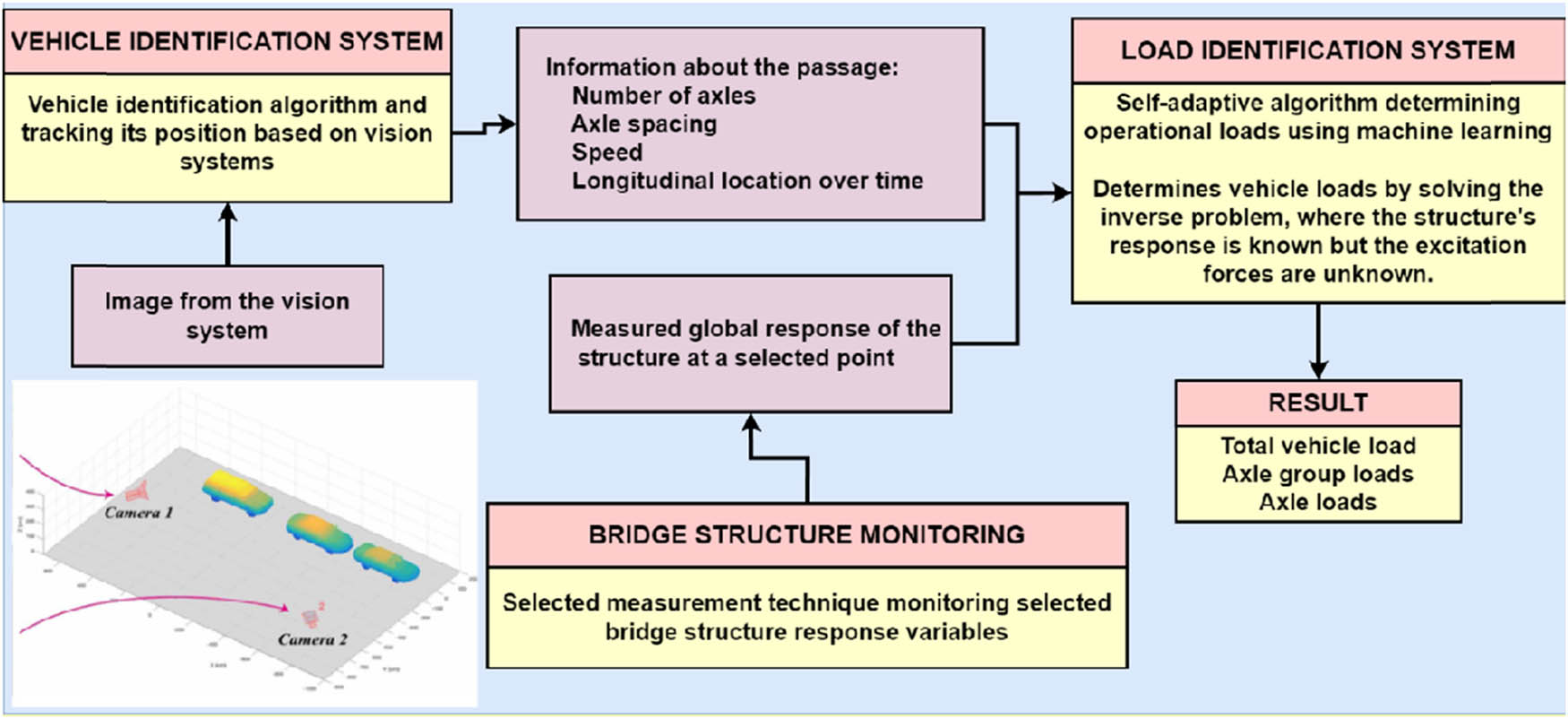
Figure 2
General concept of the proposed B-WIM system structure.
Source: Author’s contribution.
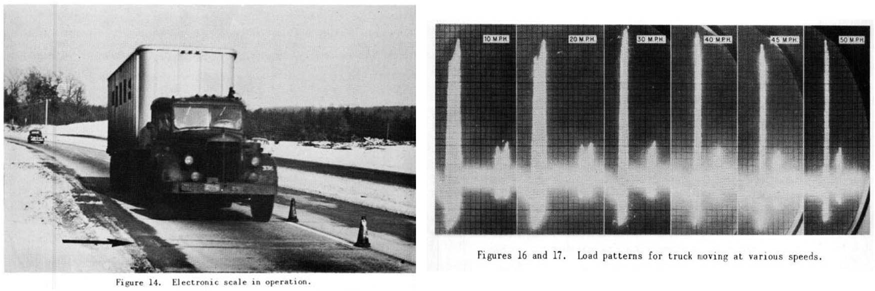
Figure 3
The passage of a tractor-trailer with a semi-trailer over a measuring device embedded in the pavement (on the left); The response of the measuring device to the passage of the vehicle at different speeds (on the right).
Source: data from [17].
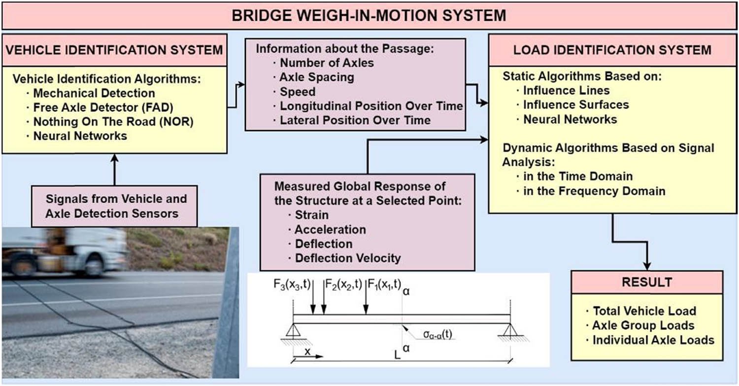
Figure 4
Diagram of a typical B-WIM system.
Source: Author’s contribution.
Table 3
Classification of vehicle identification algorithms in B-WIM systems.
| Algorithm | Typical sensor location | Results | Intended use | Literature references | |||
|---|---|---|---|---|---|---|---|
| Axle configuration | Velocity | Longitudinal location | Transverse location | ||||
| MDS | In the surface in front of the facility | ● | ● | ○ | Short-term monitoring on low- traffic facilities for low-accuracy systems | [22,24,27,28] | |
| FAD | Over support points or in points that give a clear answer | ● | ● | ○ | ○ | Continuous monitoring on medium- traffic facilities for systems with good accuracy | [25,26,29] |
| NOR | Most often in the middle of the span | ● | ● | ○ | ○ | Continuous monitoring on medium- traffic facilities for systems with good accuracy | [26,30,31,32] |
Explanation of symbols: usefulness (●) – high, (○) – medium, () – low.
Source: Author’s contribution,
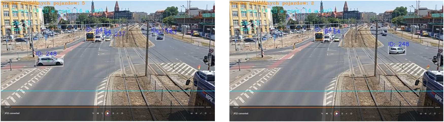
Figure 5
Identification and tracking of vehicles based on camera image.
Source: Author’s contribution.
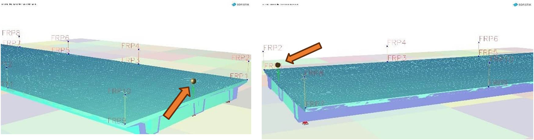
Figure 6
Screenshots of a model mass passage from two different perspectives.
Source: Author’s contribution.
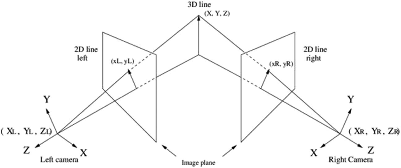
Figure 7
Stereo triangulation from a pair of cameras.
Source: data from [47].
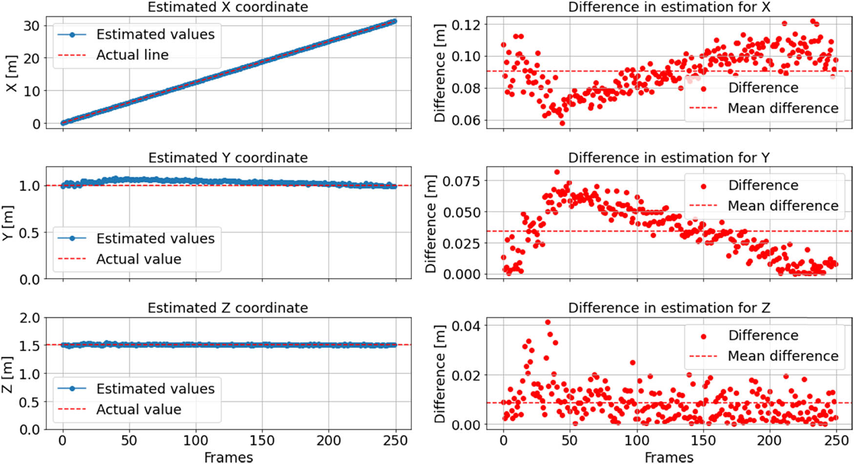
Figure 8
Comparison of estimated and actual coordinates for the tracked model mass based on screenshots triangulation, along with the corresponding estimation differences.
Source: Author’s contribution.
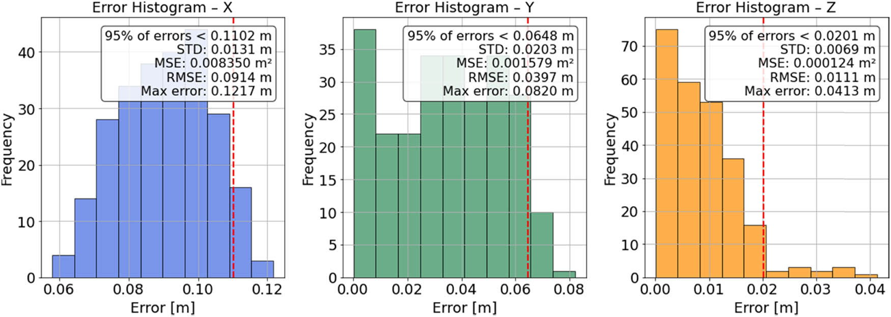
Figure 9
Estimation error histograms for the model mass position coordinates.
Source: Author’s contribution.
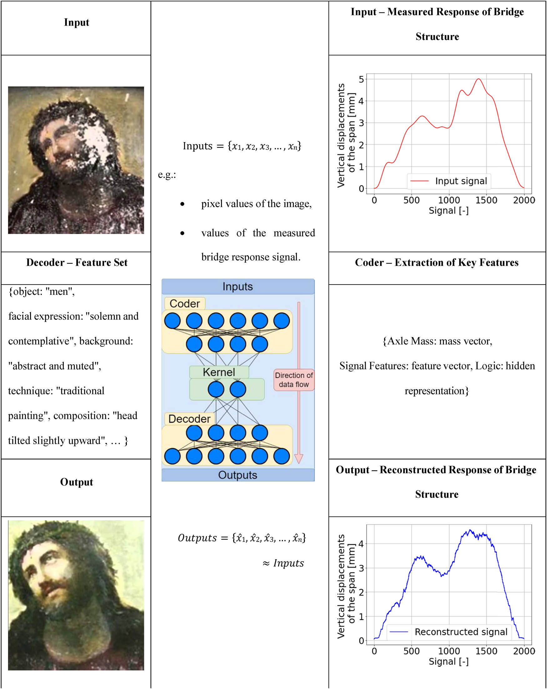
Figure 10
Experiment with image (left) and signal (right) reconstruction along with representation of the general idea of the autoencoder architecture (centre).
Source: Author’s contribution.
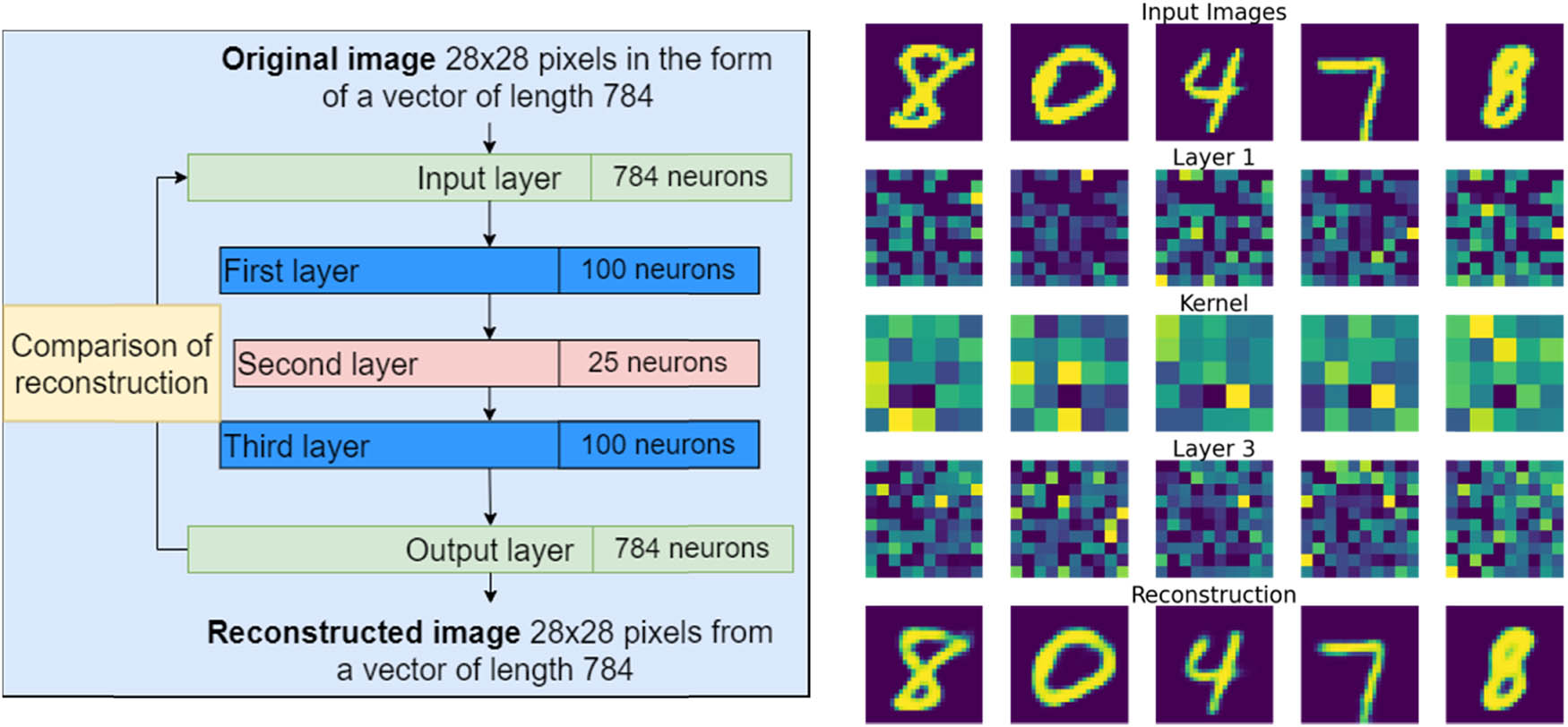
Figure 11
(a) Stacked autoencoder architecture and (b) results of the network operation in following steps.
Source: Author’s contribution.
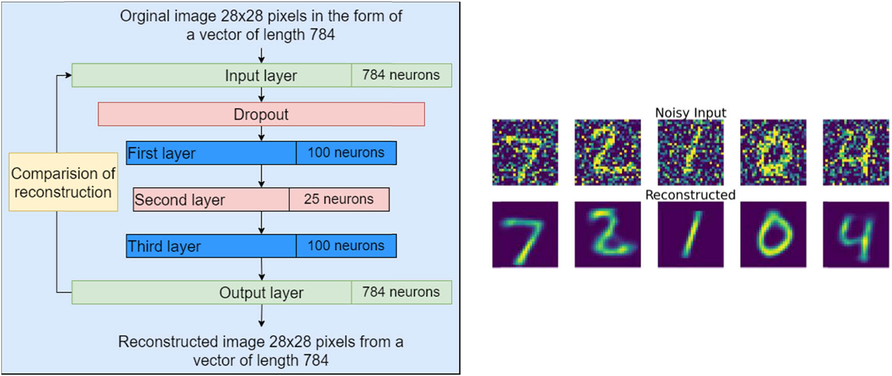
Figure 12
(a) Denoising autoencoder architecture and (b) results of the network operation in following steps.
Source: Author’s contribution.
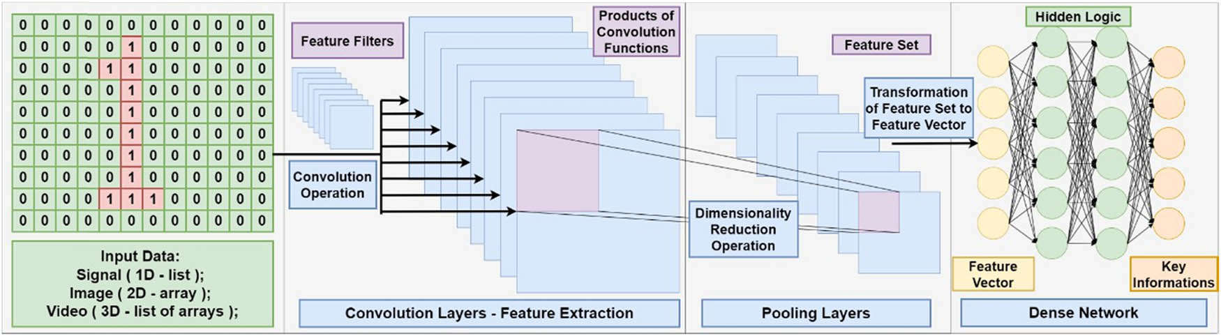
Figure 13
Typical structure of a CNN.
Source: Author’s contribution.
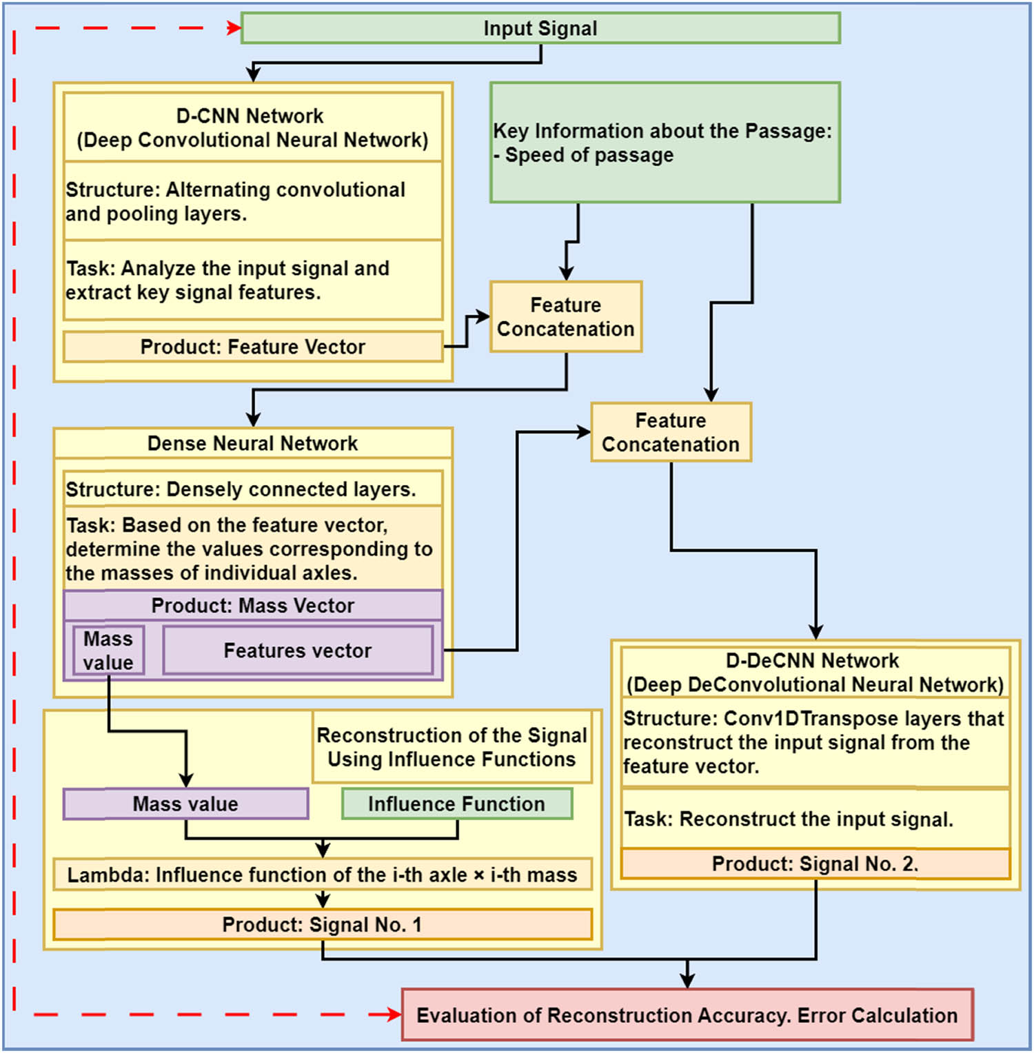
Figure 14
General block diagram of the proposed system algorithm and operation.
Source: Author’s contribution.
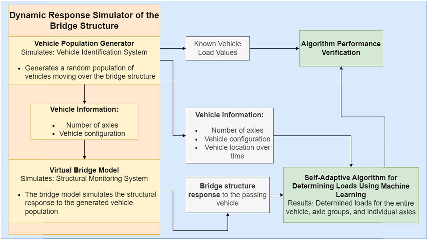
Figure 15
Implementation and testing scheme using mock system components.
Source: Author’s contribution.
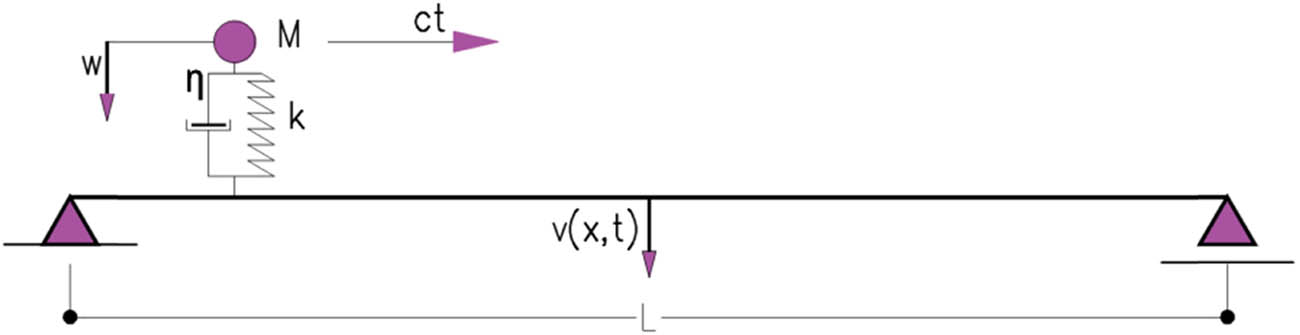
Figure 16
Virtual bridge model.
Source: Author’s contribution.
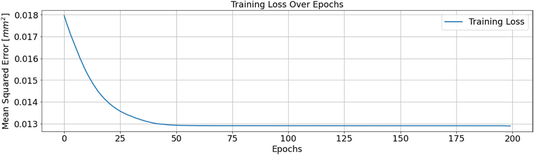
Figure 17
Learning curve values for training data.
Source: Author’s contribution.
Table 4
Determined static load values at various stages of network training.
| Static loads expressed as mass (t) | |||
|---|---|---|---|
| Mass no. 1 | Mass no. 2 | Mass no. 3 | |
| Actual value | 34.4 | 28.11 | 50.23 |
| Before training | 0.00 | 0.06 | 0.20 |
| After training | 34.6 | 28.23 | 49.99 |
| Error | 0.57% | 0.41 | 0.48 |
Source: Author’s contribution.
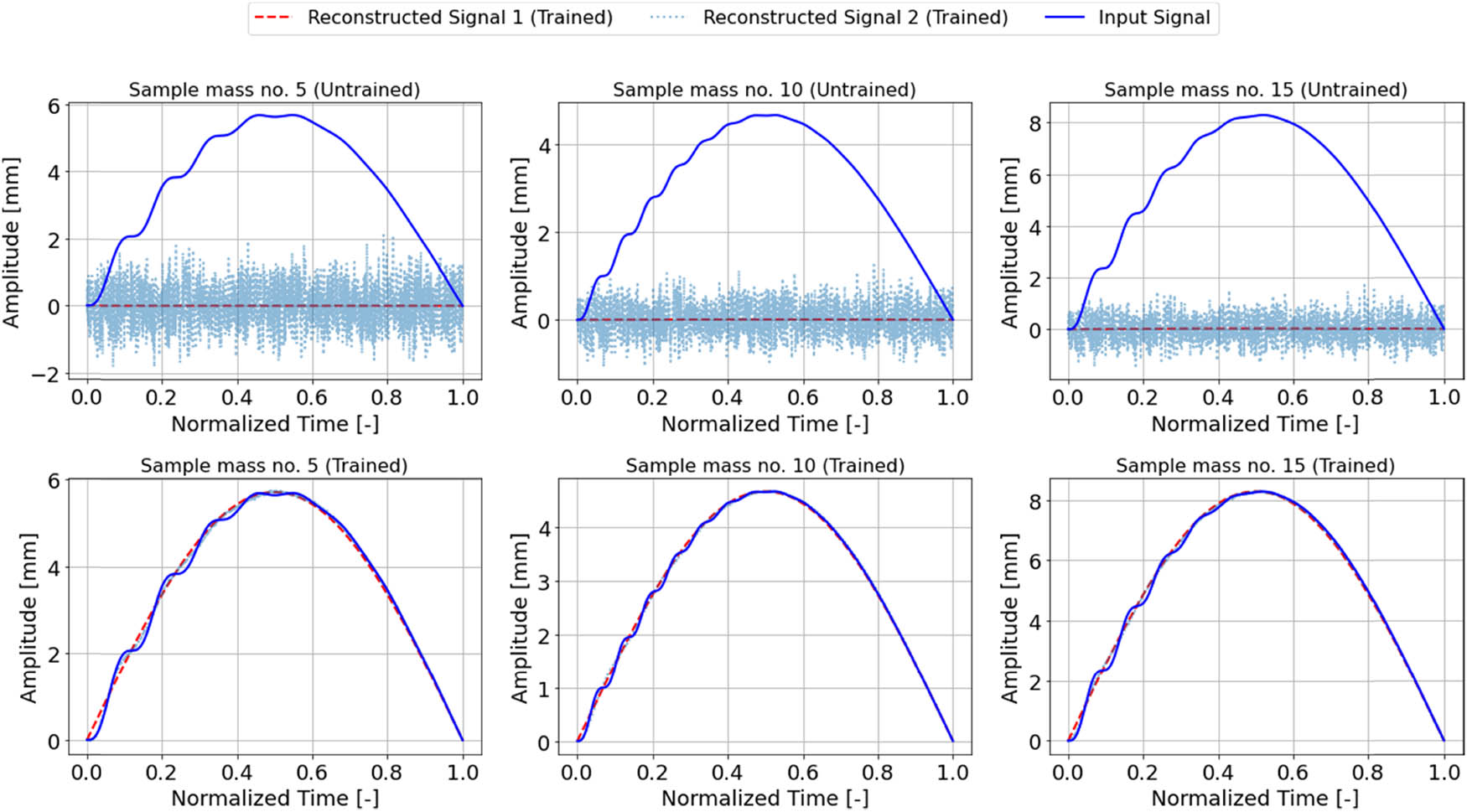
Figure 18
Comparison of reconstructed signals with the original for different training phases.
Source: Author’s contribution.
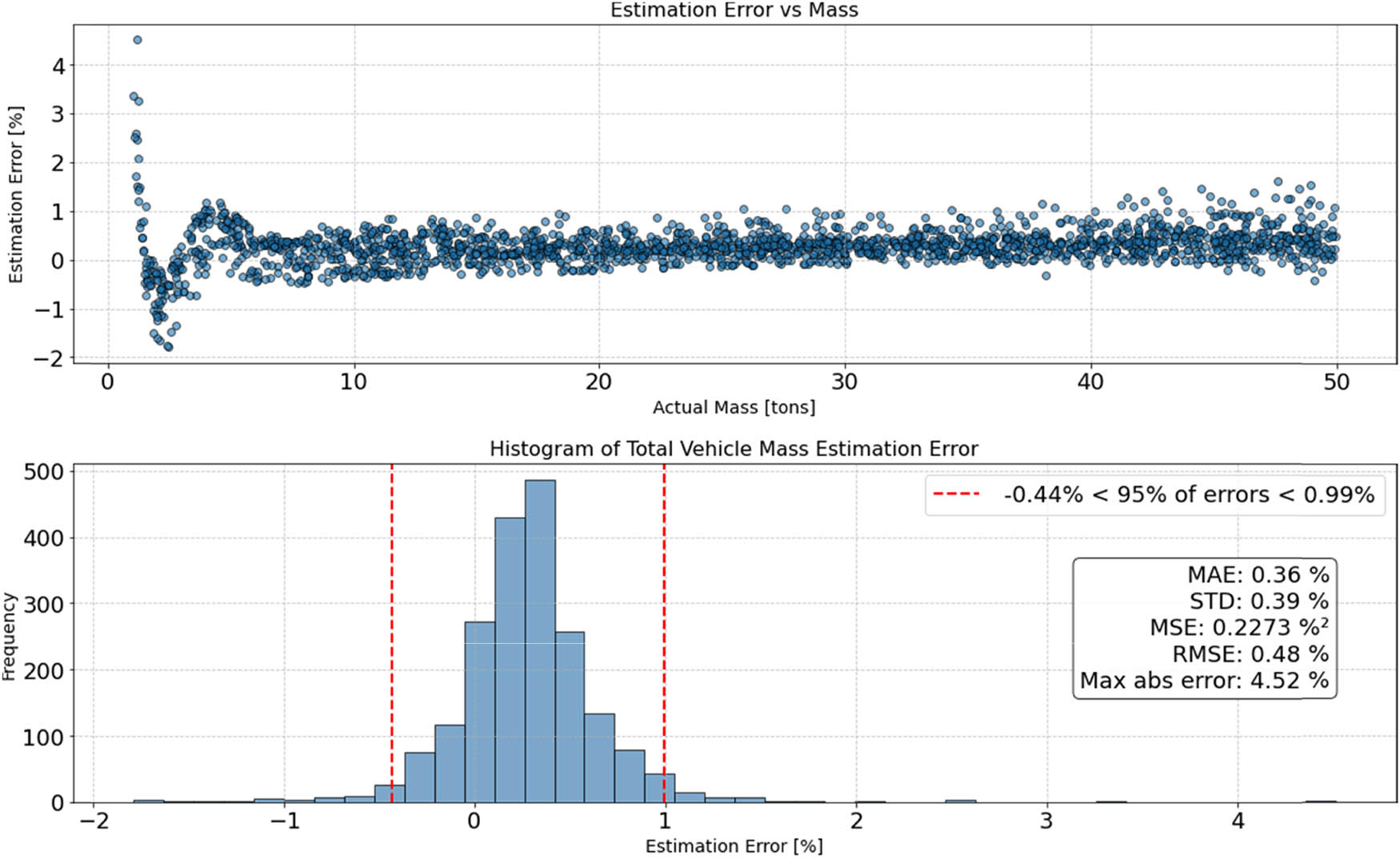
Figure 19
The estimation error for the test population.
Source: Author’s contribution.