
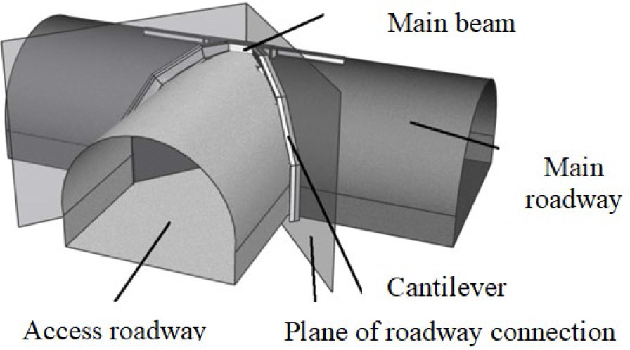
Figure 1:
Assumptions in the design of roadway junction supports (Rotkegel, 2013).
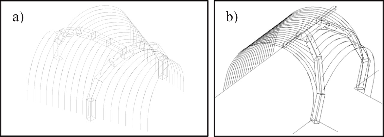
Figure 2:
Spatial sketches of typical portal supports for three-way junctions: (a) at an acute angle and (b) at a right angle (Rotkegel, 2015).
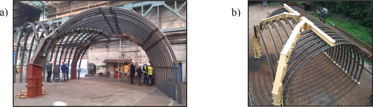
Figure 3:
Examples of portal support implementation for three-way junctions: (a) at an acute angle and (b) at a right angle (Rotkegel, 2015).
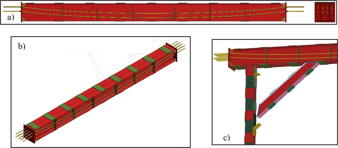
Figure 4:
Support structure made of steel I-beams with the canopy reinforced by pre-tensioned cables: (a) cross section of canopy, (b) canopy with pre-tensioned cables and (c) position of canopy attached with column legs.
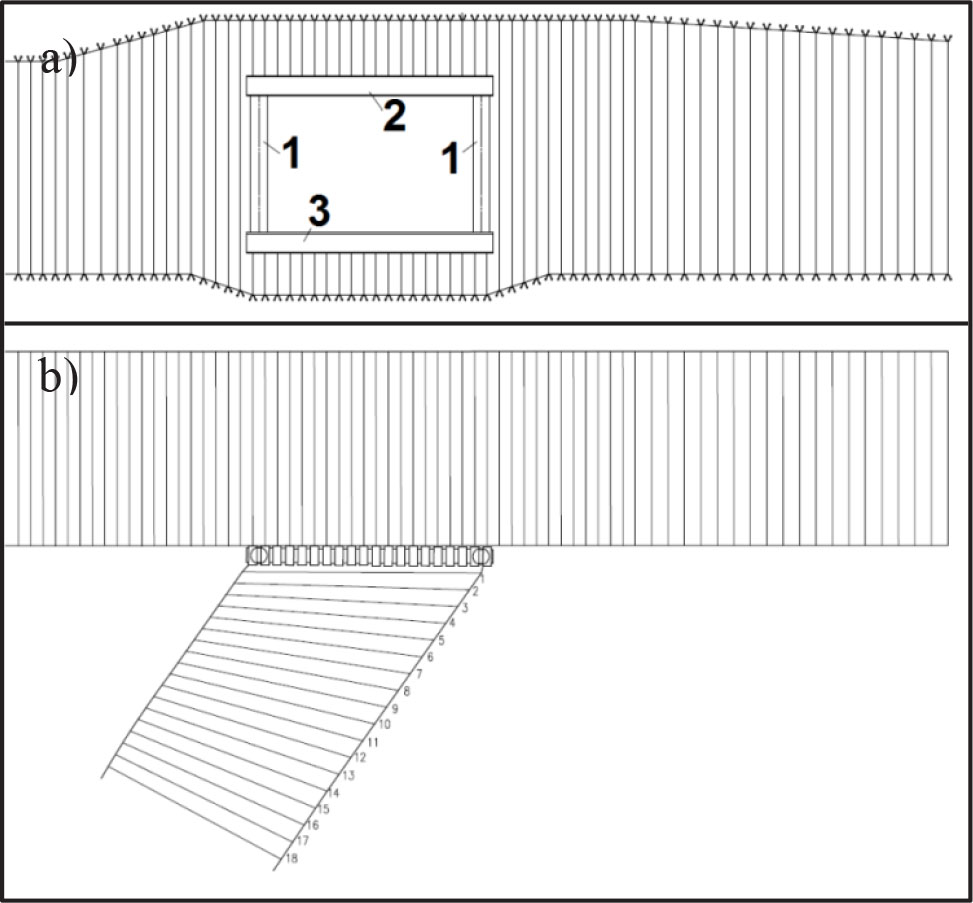
Figure 5.
Example of support for the roadway junction in the form of a rectangular portal: (a) cross section and (b) top view (1 – column legs, 2 – canopy, 3 – floor base).
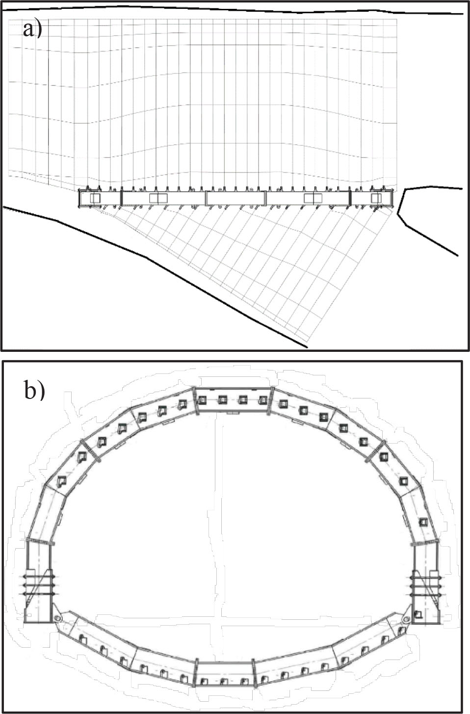
Figure 6:
Example of polygonal portal made in the form of an arch – a support construction designed for the Bogdanka coal mine: (a) top view and (b) cross section.
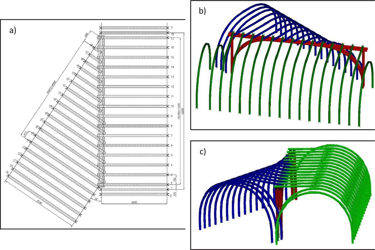
Figure 7:
The three-way roadway junction support is based on a portal made of the V profile steel frames: (a) top view and (b and c) cross section.
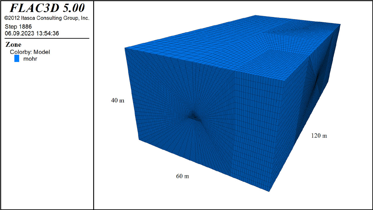
Figure 8:
Numerical model of rock mass in FLAC3D.
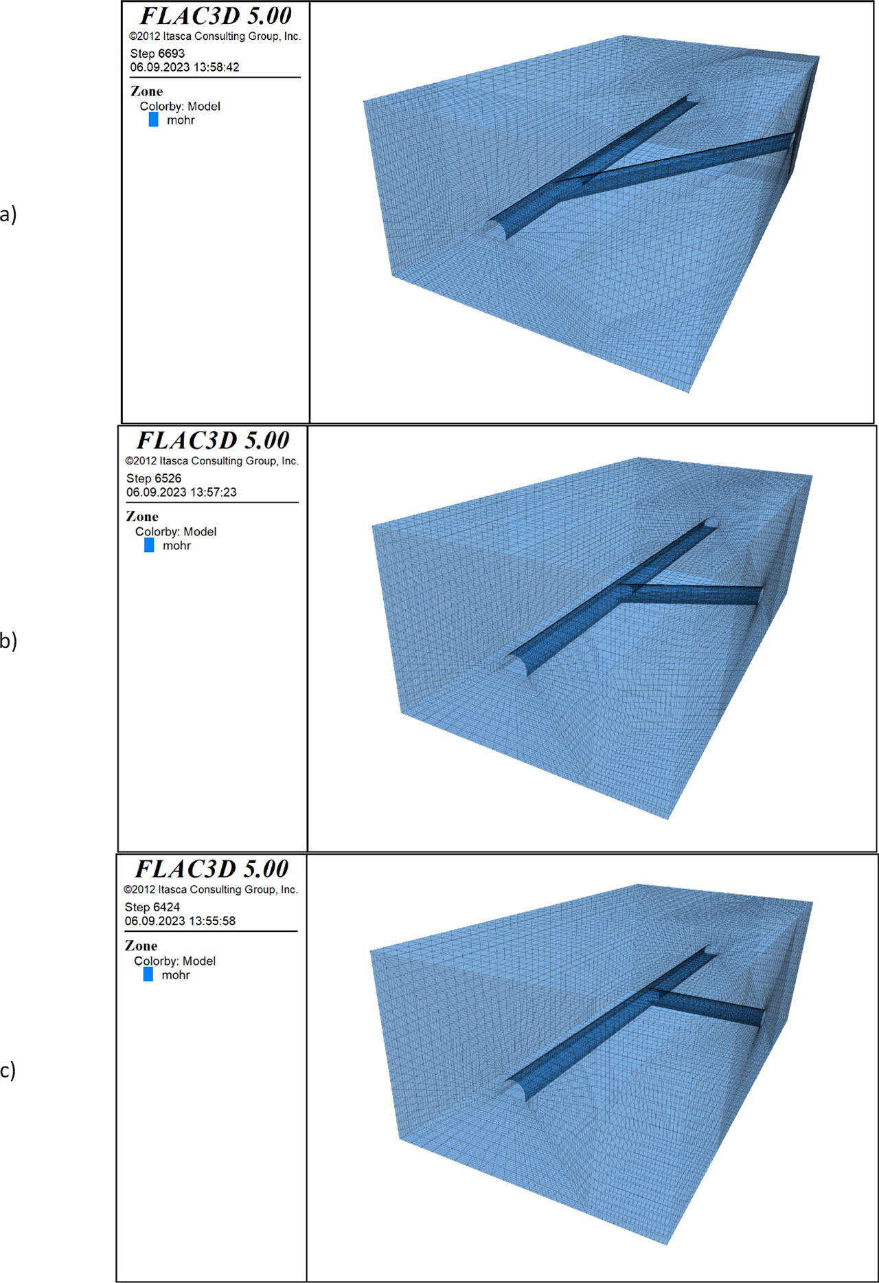
Figure 9:
Numerical model of the coal mine roadway and the configuration of their connection at different angles: (a) 30°, (b) 60° and (c) 90°.
Table 1:
Mechanical parameters of rock mass in the Cam Pha coal basin, Vietnam.
| Rock type | Bulk modulus, K (GPa) | Shear modulus, G (GPa) | Friction angle φ (deg.) | Cohesion c (MPa) | Tensile strength Rt (MPa) | Density ρ (kg/m3) |
|---|---|---|---|---|---|---|
| Sandstone | 3.94 | 2.58 | 32 | 4.0 | 1.20 | 2500 |
| Mudstone | 2.33 | 1.40 | 30 | 2.0 | 0.56 | 2700 |
| Claystone | 1.67 | 1.00 | 28 | 1.2 | 0.25 | 2600 |
| Coal | 1.25 | 0.58 | 25 | 0.8 | 0.10 | 1400 |
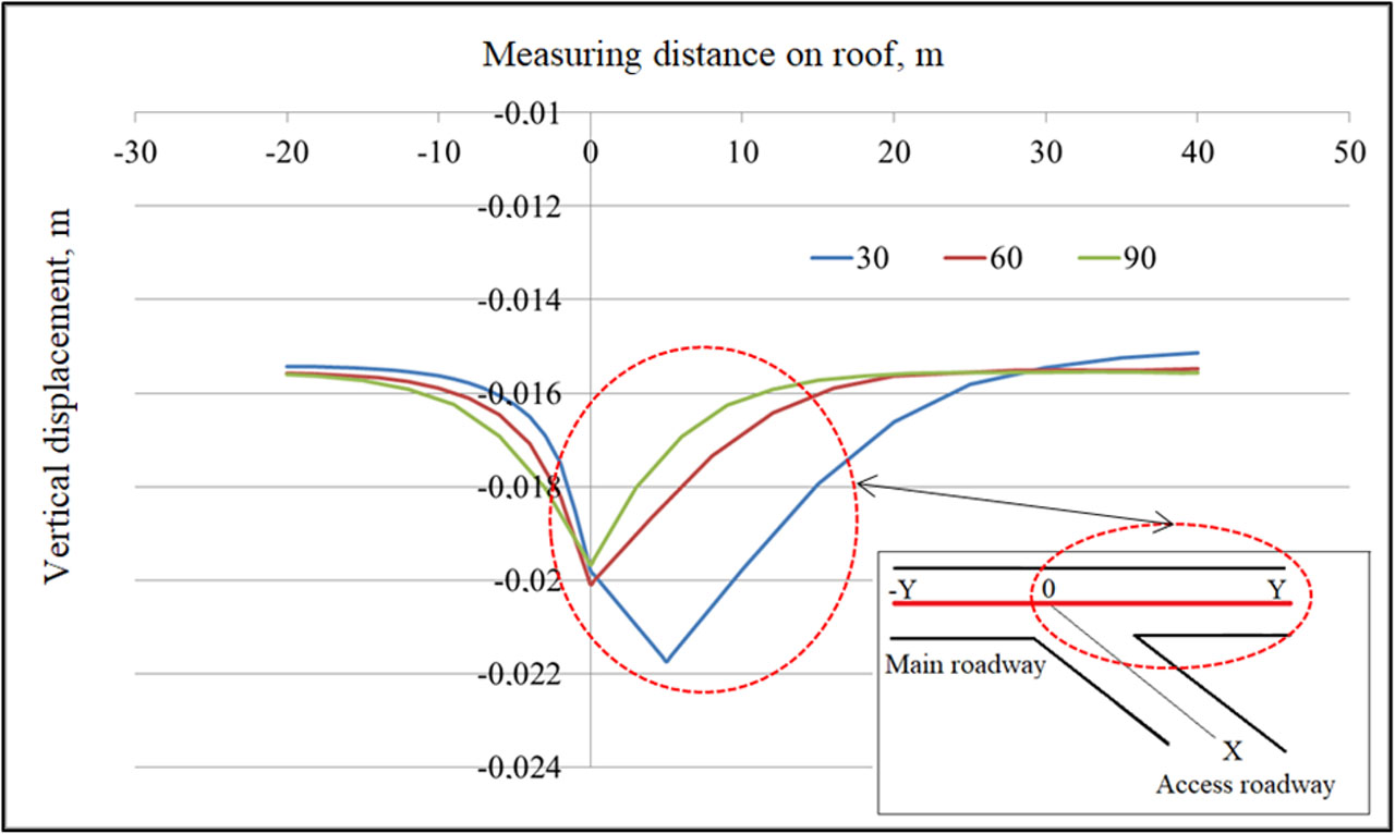
Figure 10:
Vertical displacement of roof rock in the main roadway.
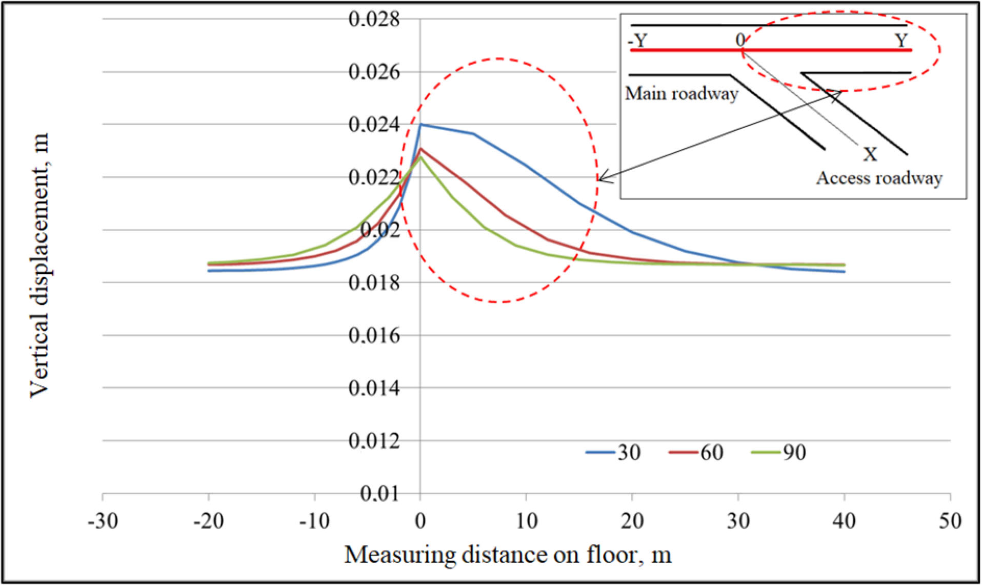
Figure 11:
Vertical displacement of floor rock in the main roadway.
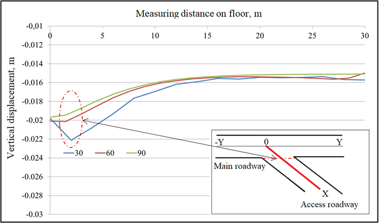
Figure 12:
Vertical displacement of roof rock in the access roadway.
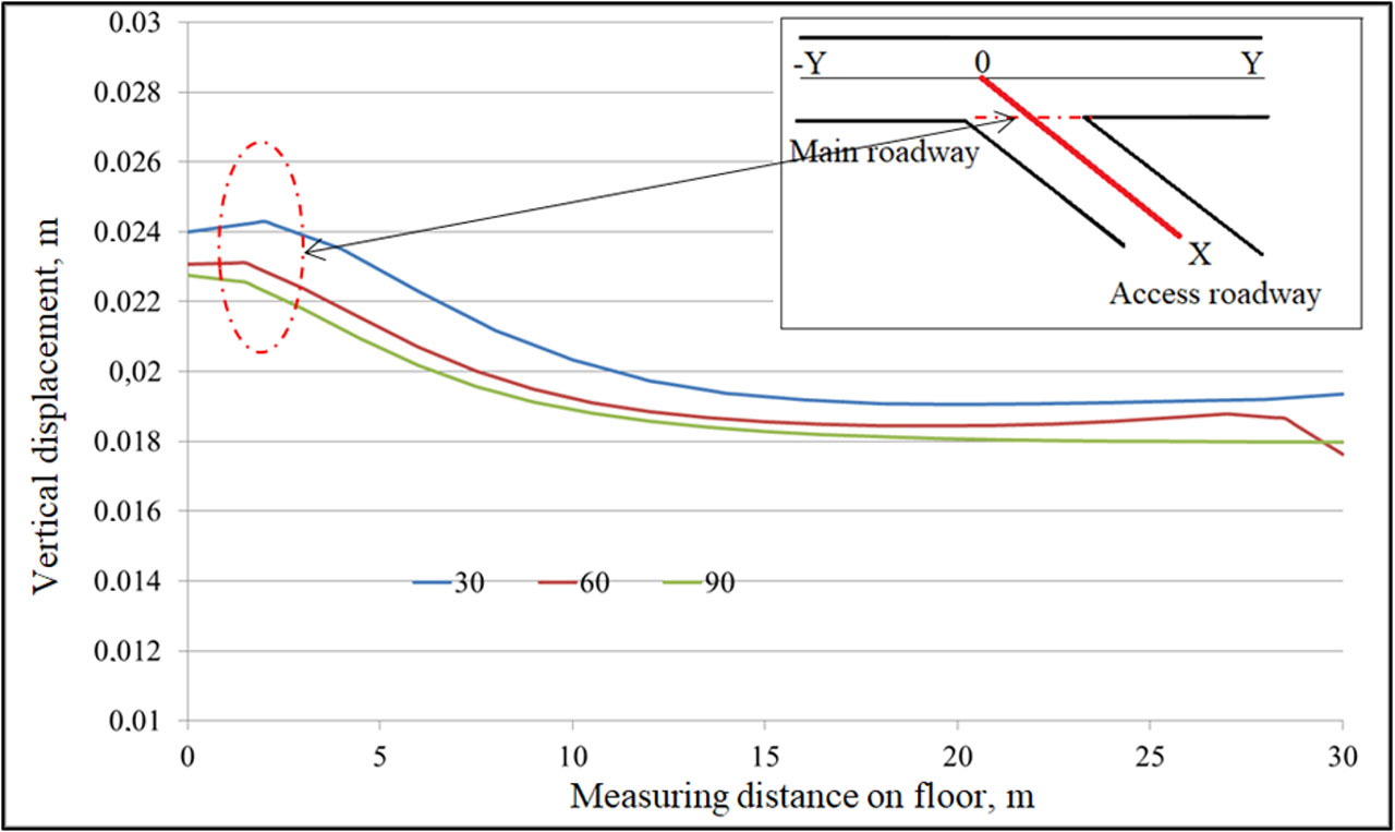
Figure 13:
Vertical displacement of floor rock in the access roadway.
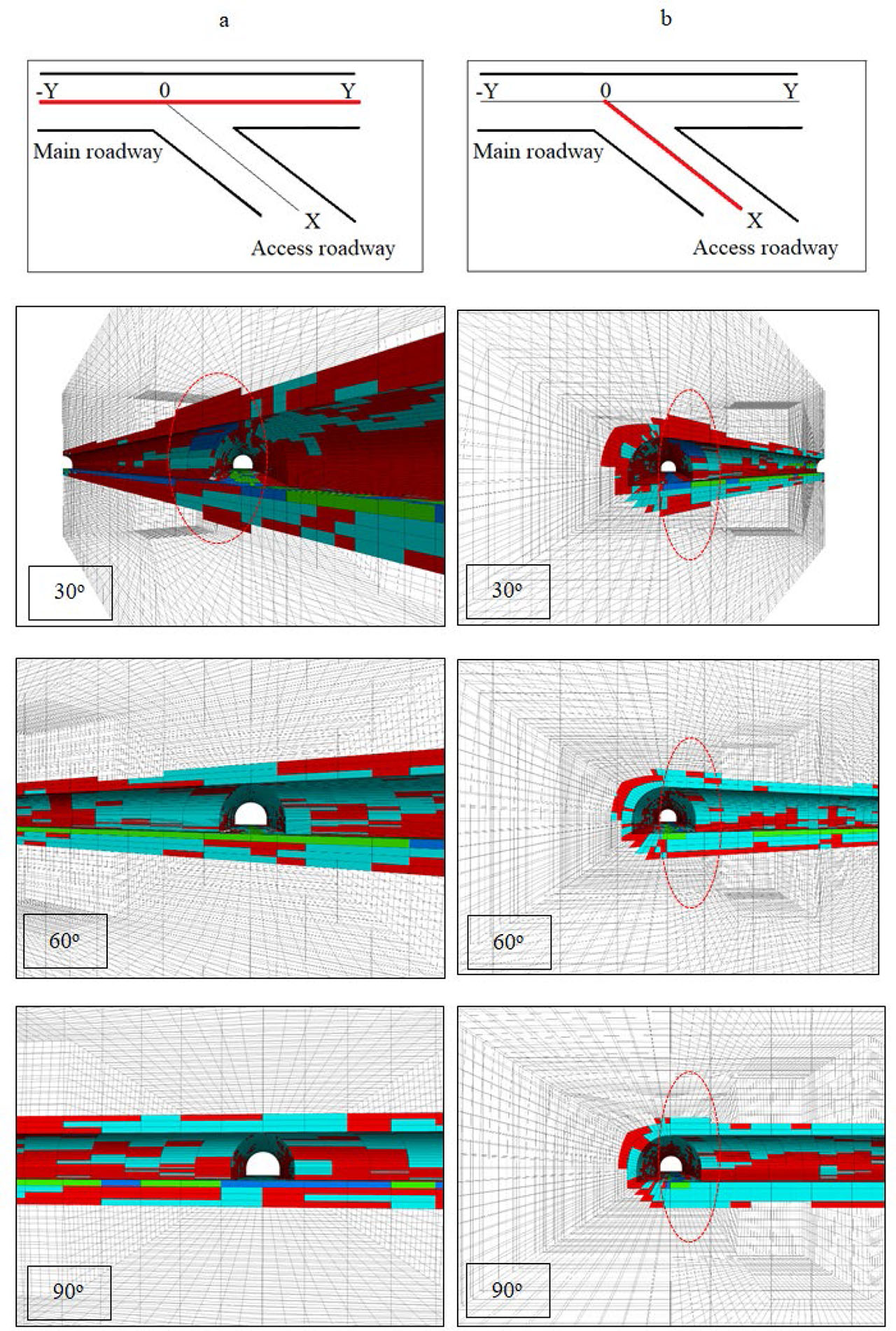
Figure 14:
Failure zone of rock mass around the three-way roadway junction: (a) along the main roadway and (b) along the access roadway.

Figure 15:
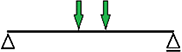
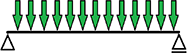
Load patterns for the canopy beam.
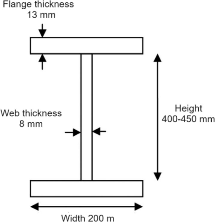
Figure 16:
Dimensions of I-beam adopted for modelling.
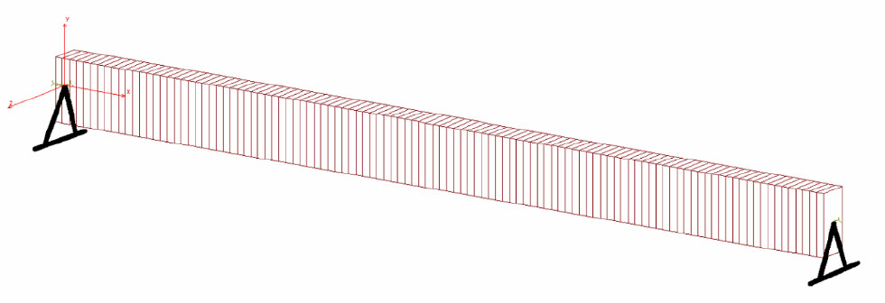
Figure 17:
Model of canopy made of a simple I-beam – Beam model.
Table 2:
Maximum values of bending moments Mg and beam deflections f for individual loading patterns according to analytical calculations.
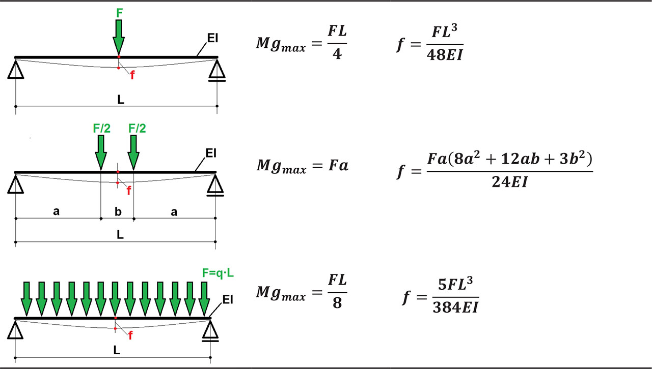
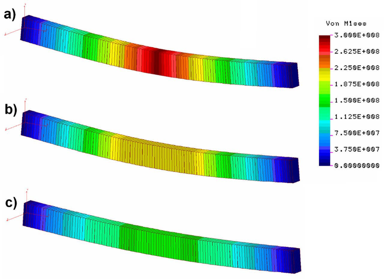
Figure 18:
Distribution of reduced stresses (Pa) in the beam model of a canopy made of a single I-beam for various load patterns: (a) one-point load, (b) two-point load and (c) evenly distributed load.
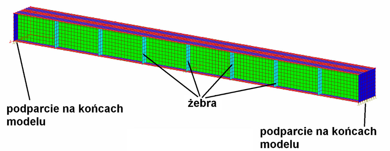
Figure 19:
Model of a canopy made of two I-beams with additional ribs – Shell model.
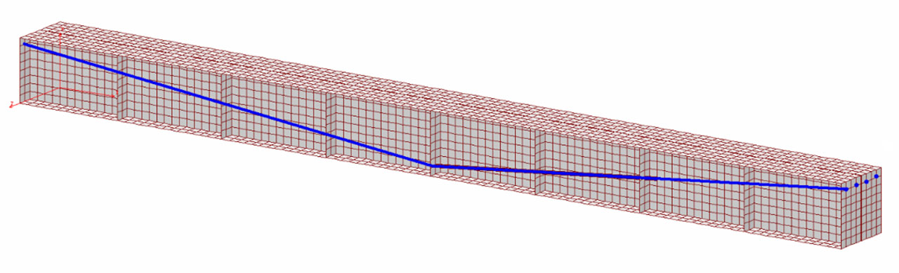
Figure 20:
Model of a canopy made of two I-beams with one line of cables (Shell model + 4 cables).
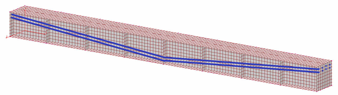
Figure 21:
Model of a canopy made of two I-beams with two lines of cables (Shell model + 8 cables).
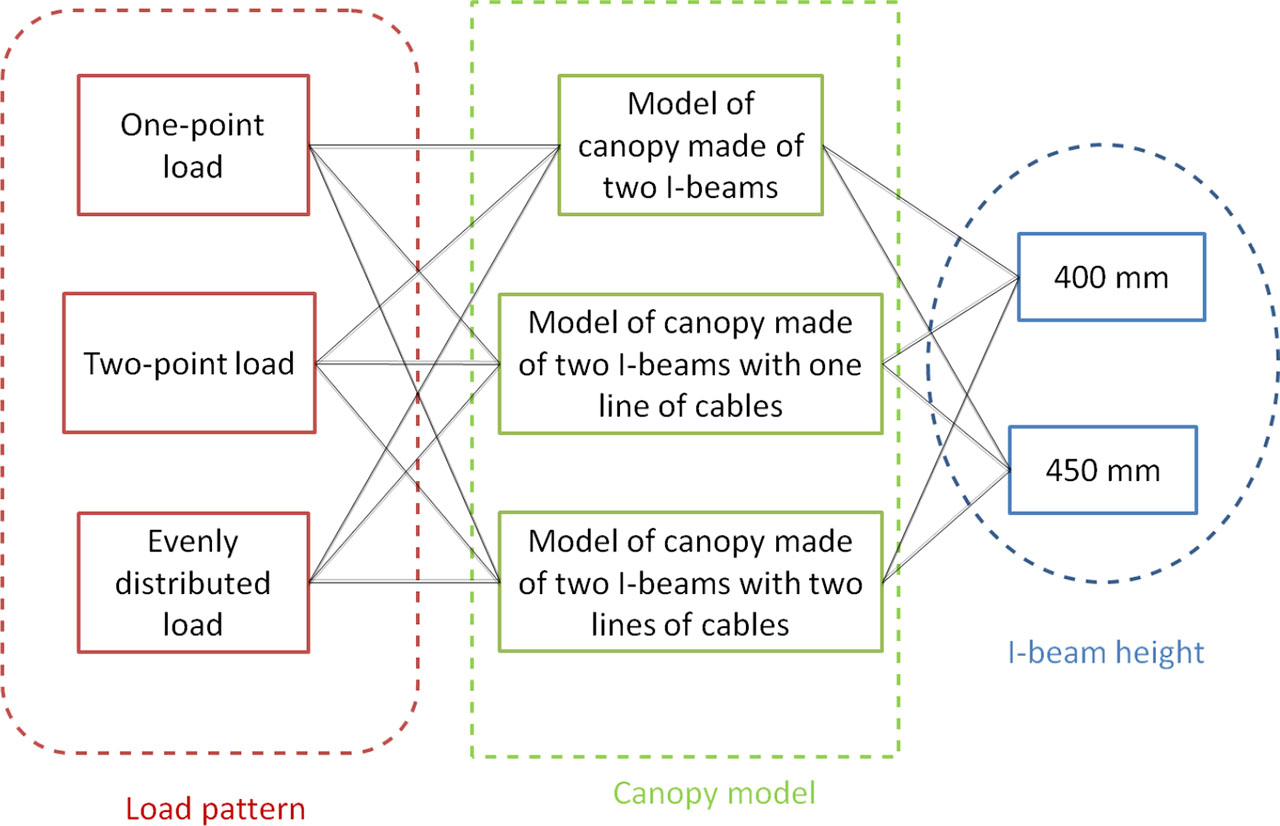
Figure 22:
Calculation variants.
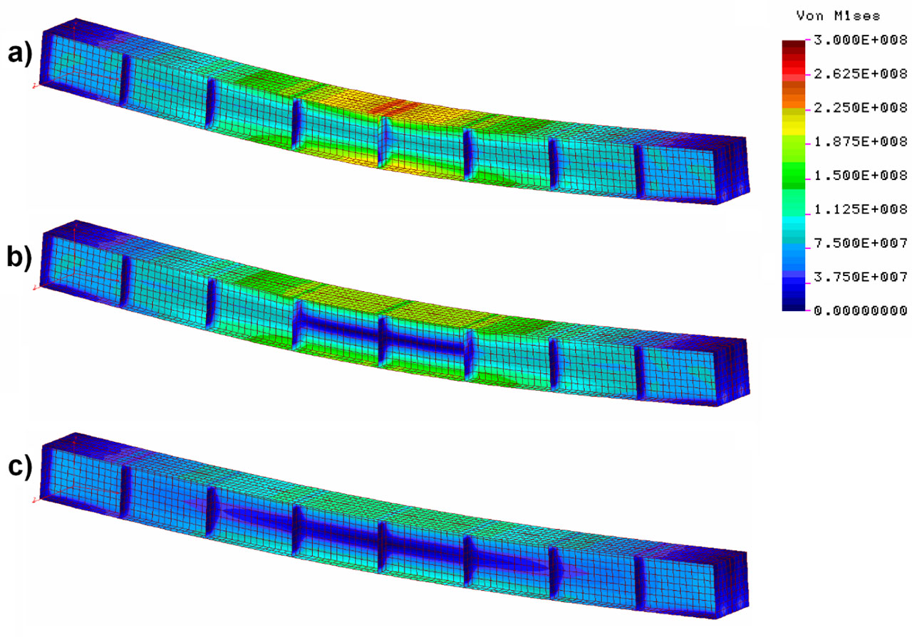
Figure 23:
Map of reduced stresses (Pa) in a model of a canopy made of two I-beams: (a) one-point load, (b) two-point load and (c) evenly distributed load (loading force – 500 kN).
Table 3:
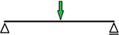
Comparison of results of the bearing capacity analyses for the shell model and the beam model.
| Load pattern | Shell model | Beam model | ||
|---|---|---|---|---|
| Max. reduced stress, σred, MPa | Max. deflection, ƒ, mm | Max. reduced stress, σred, MPa | Max. deflection, ƒ, mm | |
 | 258.21 | 15.91 | 292.5 | 18.44 |
 | 189.90 | 14.13 | 218.1 | 16.80 |
 | 118.87 | 9.72 | 146.3 | 11.52 |
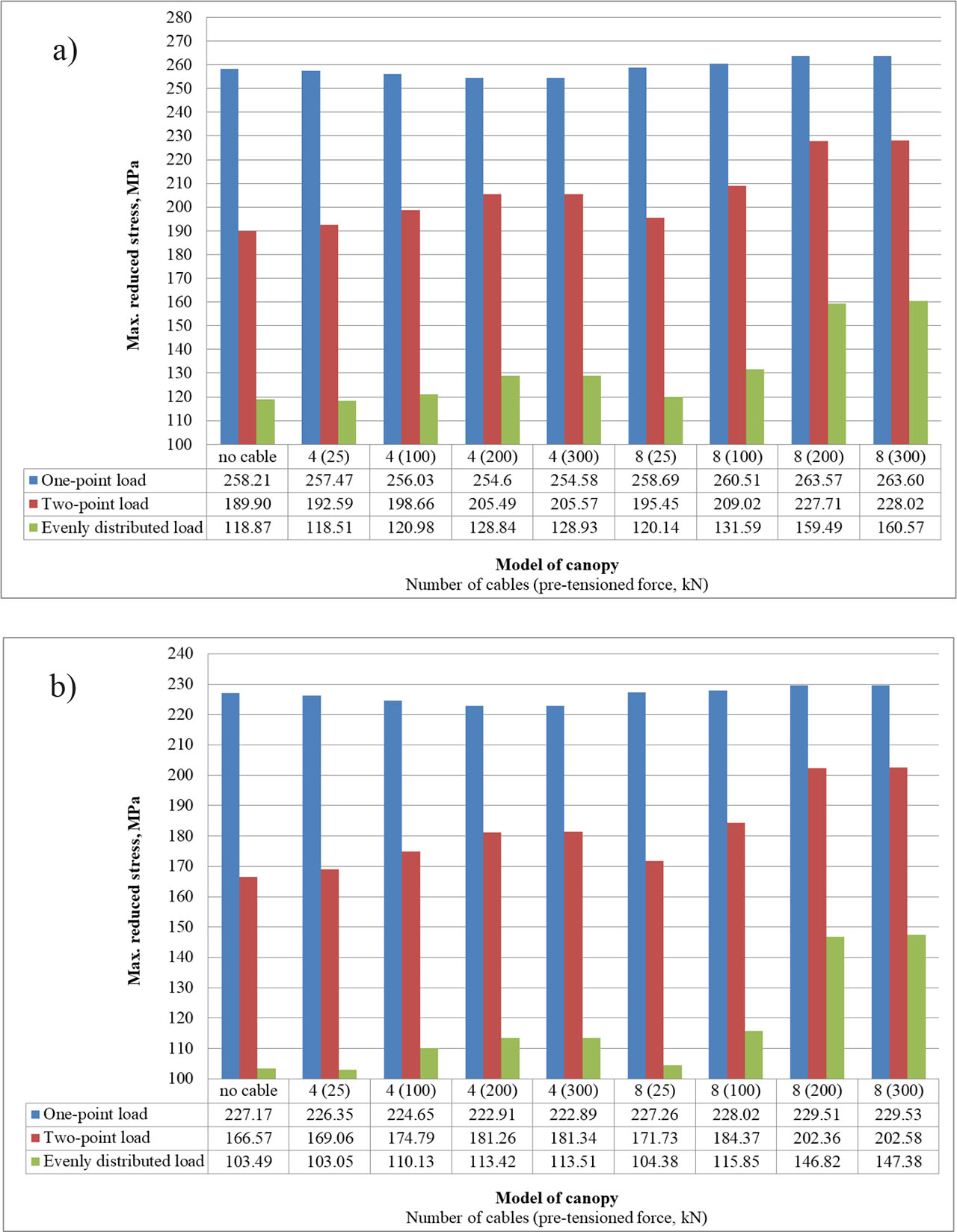
Figure 24:
Maximum values of reduced stress of canopy for individual calculation variants: (a) 400-mm I-beam and (b) 450-mm I-beam (loading force – 500 kN).
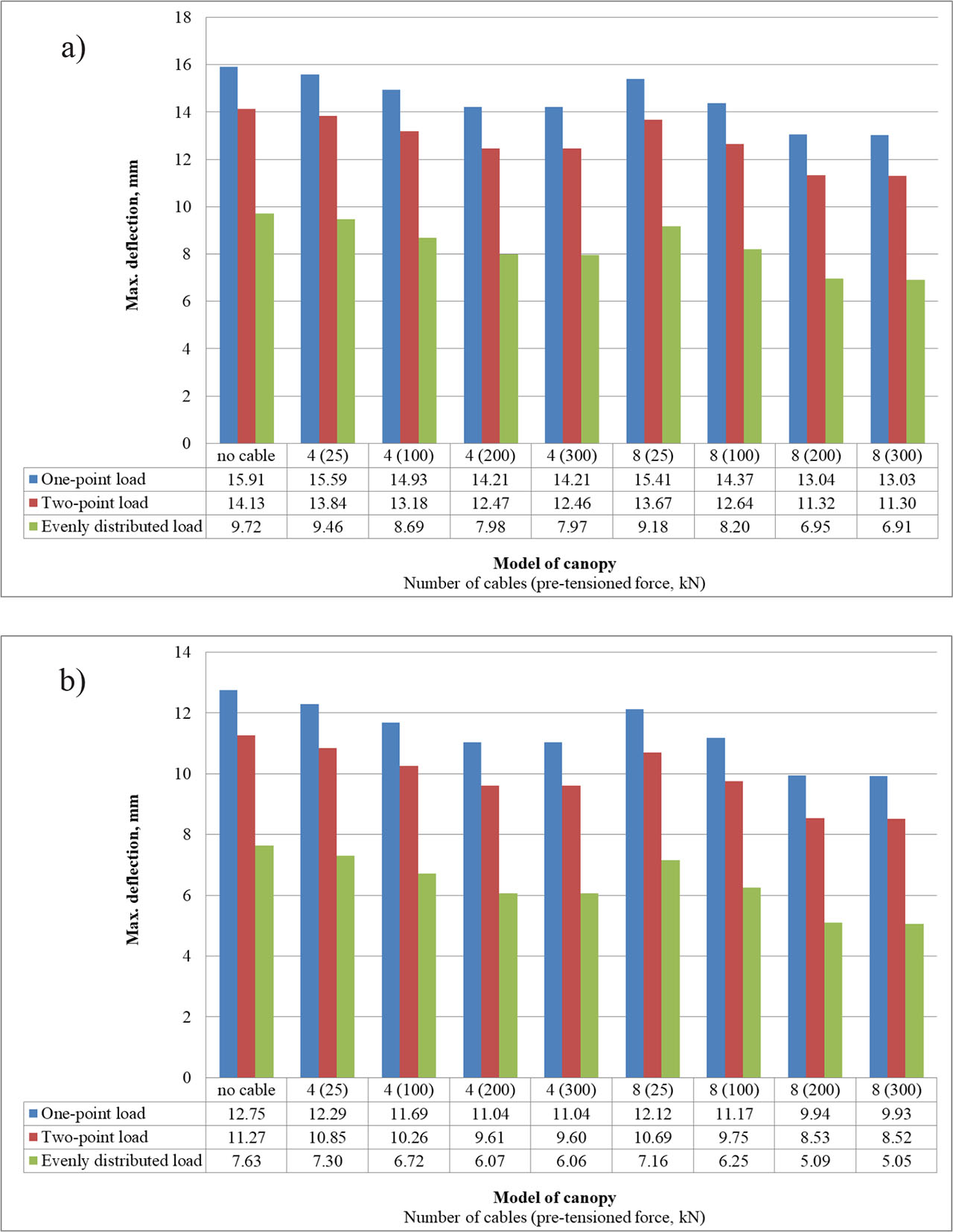
Figure 25:
Maximum values of canopy deflection for individual calculation variants: (a) 400-mm I-beam and (b) 450-mm I-beam (loading force – 500 kN).
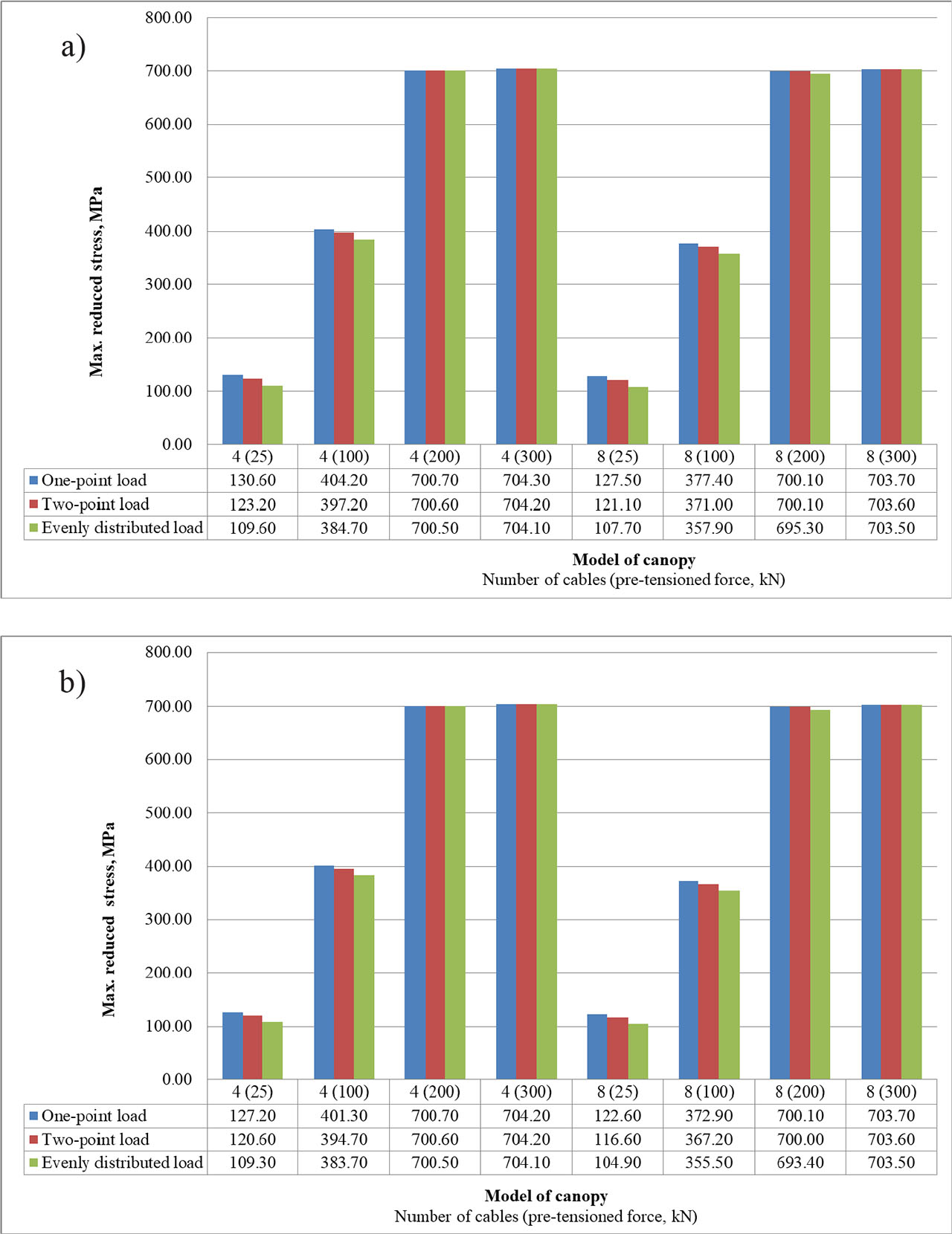
Figure 26:
Maximum values of reduced stress of cables for individual calculation variants: (a) 400-mm I-beam and (b) 450-mm I-beam (yield strength of steel – 700 MPa)
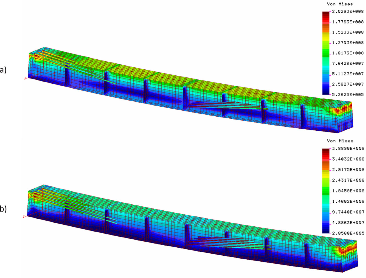
Figure 27:
Concentration of stresses (Pa) in the area of cable connections (canopy model made of two 400-mm I-beams with evenly distributed load of 500 kN, pre-tensioned force of cable of 200 kN): (a) one line of cables – 4 cables and (b) two lines of cables – 8 cables.