
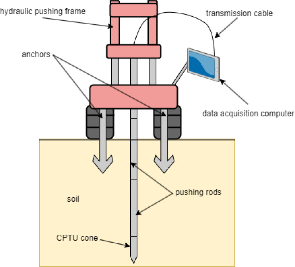
Figure 1:
CPTU probe test scheme.
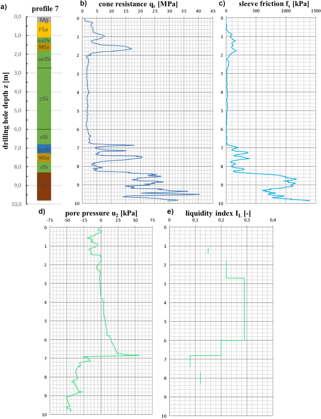
Figure 2:
An example of a research point consisting of: a) a cross section of the borehole, where Sa – sand, Si – silt, Cl – clay, Mg – made ground, Gr – gravel; b–d) graphs of the basic parameters of CPTU probing, such as qc, fs, and u2; e) a graph of the calculated laboratory values of the liquidity index IL for the selected layers.
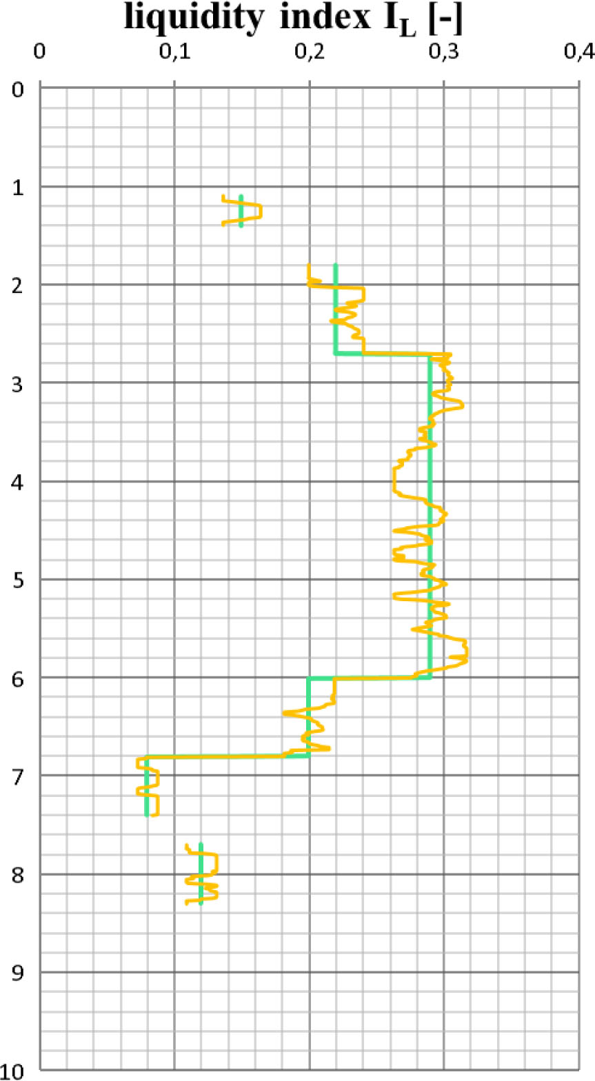
Figure 3:
Liquidity index IL before (green line) and after (orange line) transformation for the example research point.
Table 1:
Division of soil types into categories.
| Soil types | Symbol | Category |
|---|---|---|
| Made ground | Mg | 1 |
| Fine sand | FSa | 2 |
| Medium sand | MSa | 3 |
| Glacial till | siSa, clSa, sasiCl | 4 |
| Settled deposits | clSi, saSi, Si, | 5 |
| Settled deposits with gravel | grsaSi, grclSi | 6 |
| Gravel | Gr | 7 |
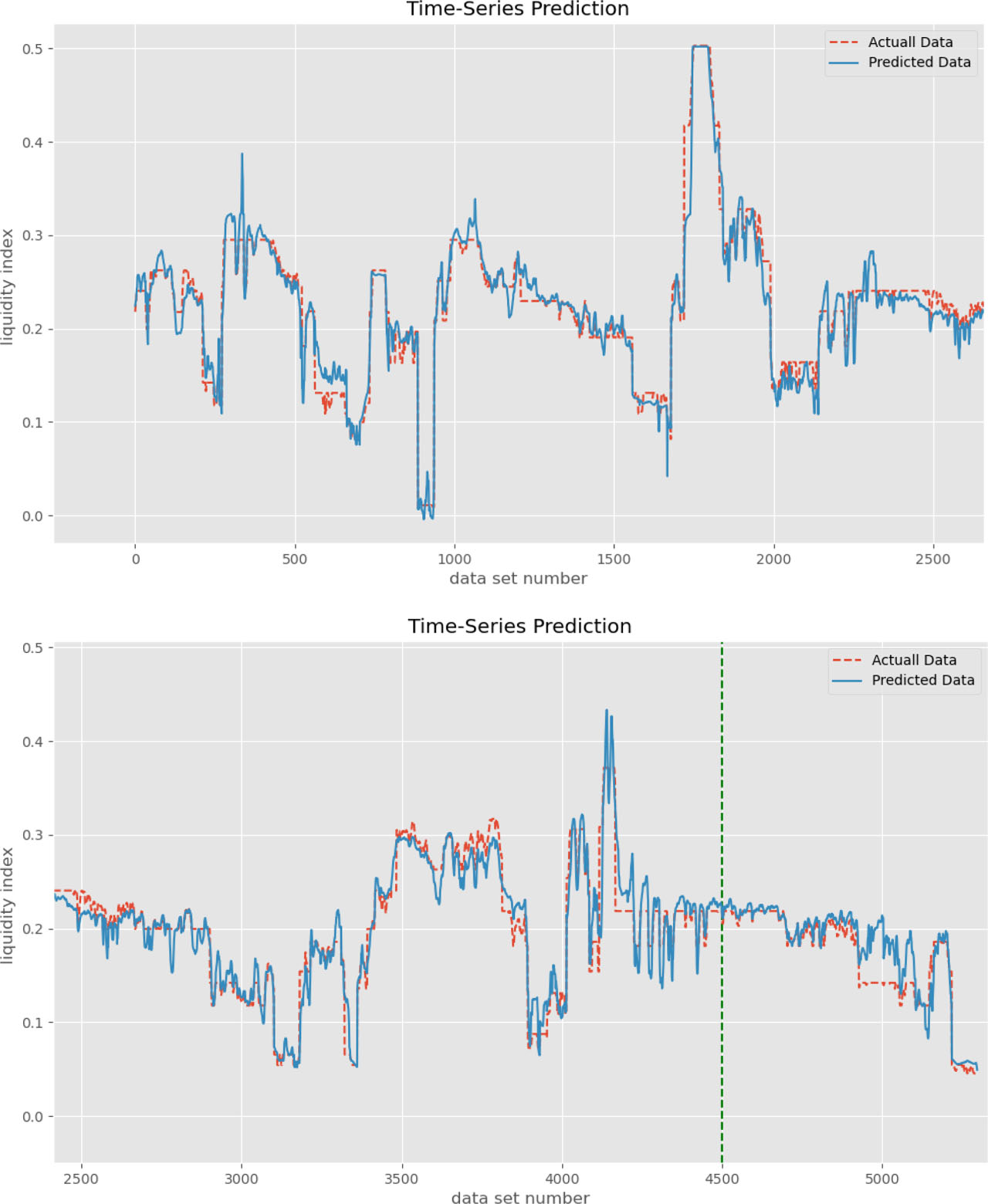
Figure 4:
Results of identification of liquidity index with the developed LSTM network in comparison with known values of the liquidity index. Explanation in the text.
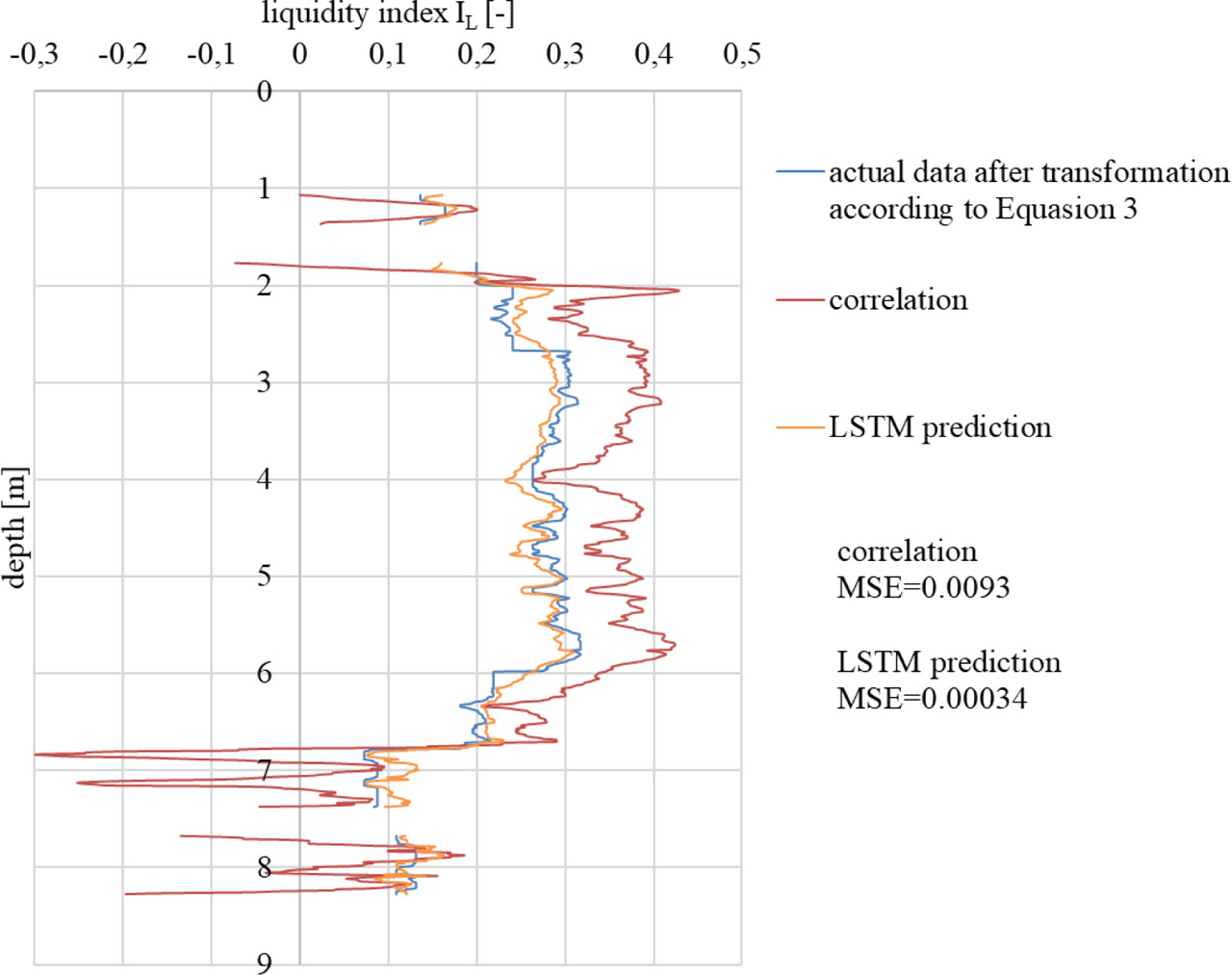
Figure 5:
Comparison of the obtained results with the correlation proposed by PN-B-04452:2002 and with laboratory results transformed by Equation 3 for profile number 7.
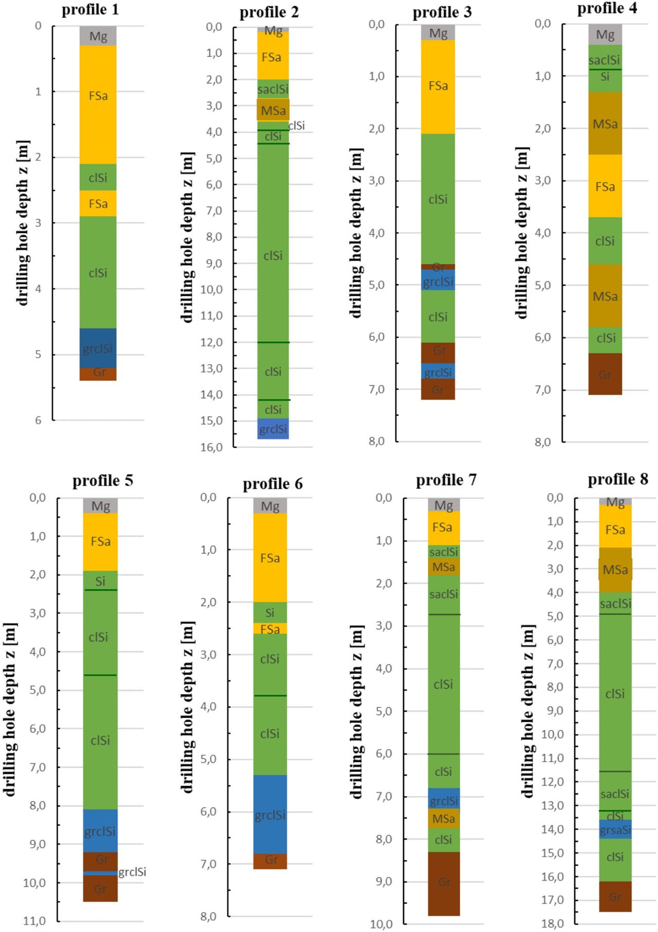
Figure 5:
Borehole profiles.
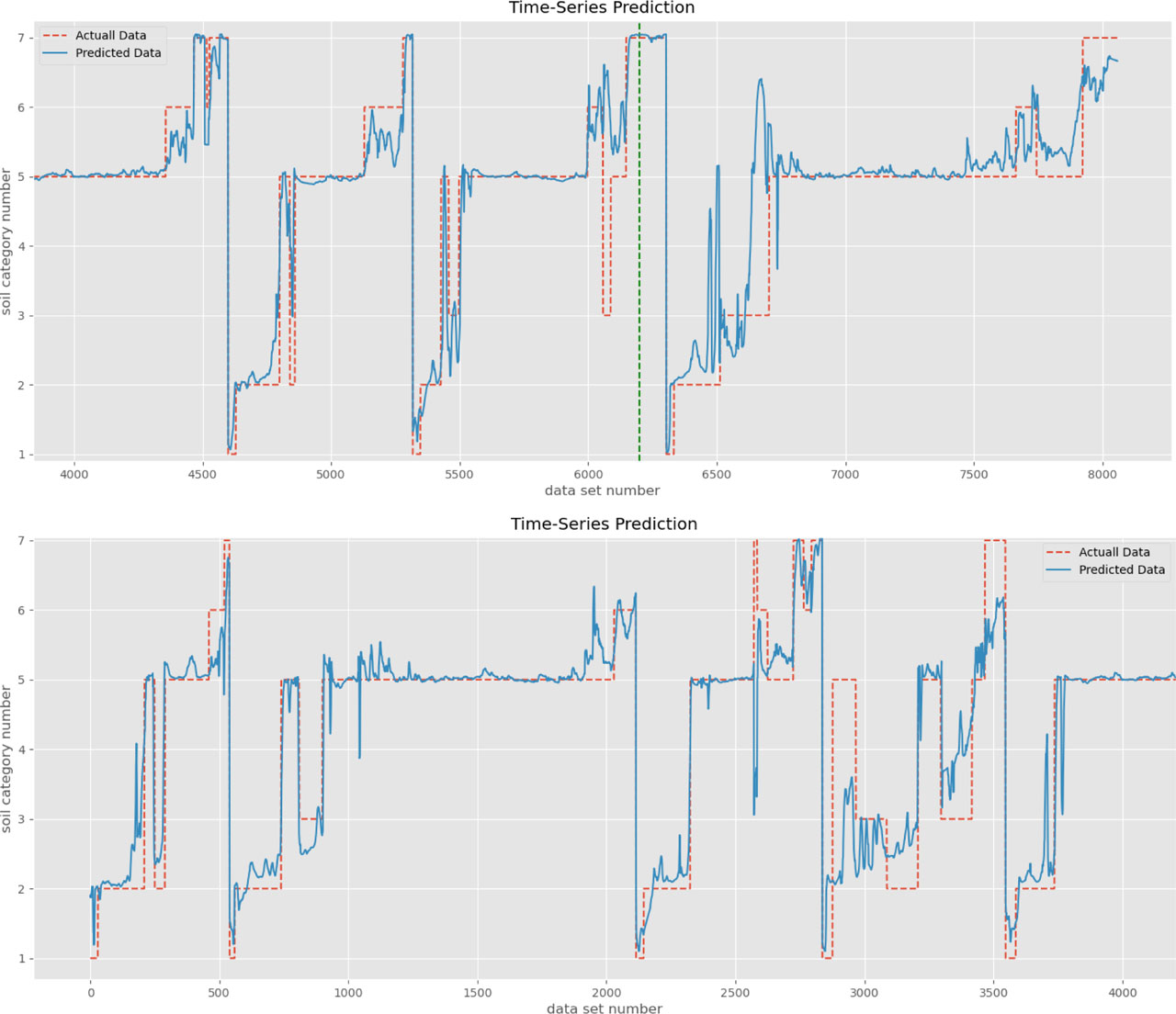
Figure 6:
Results of identification of soil type with the developed LSTM network (predicted data) in comparison with known borehole profiles (actual data). The profile includes the following data numbers: profile 1 (0–540), profile 2 (540–2115), profile 3 (2115–2837), profile 4 (2837–3547), profile 5 (3547–4600), profile 6 (4600–5318), profile 7 (5318–6304), profile 8 (6304–8060).