
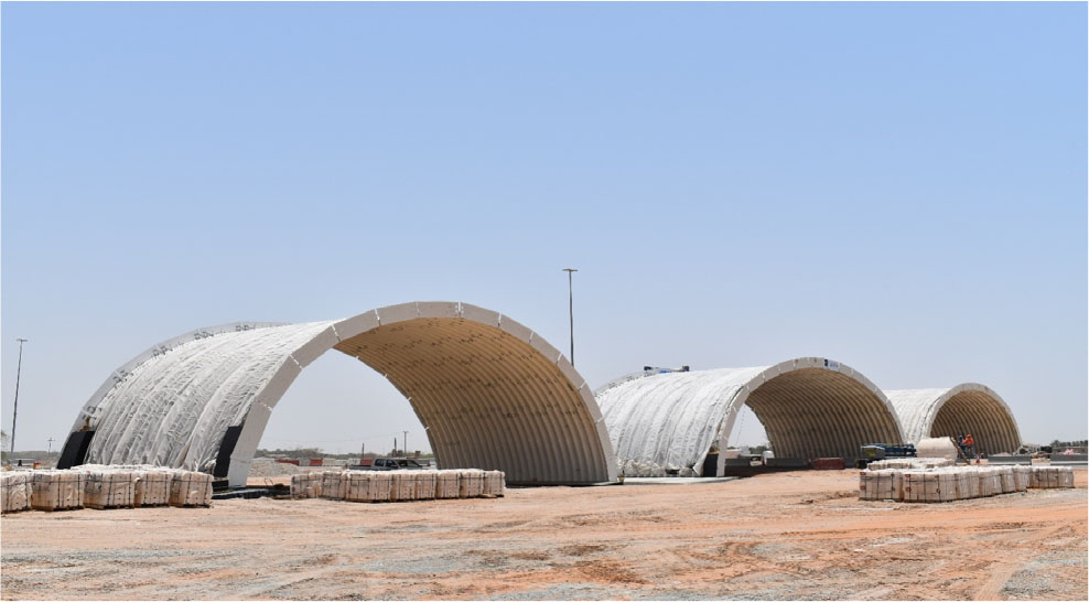
Figure 1:
Grade separation during construction – general view.
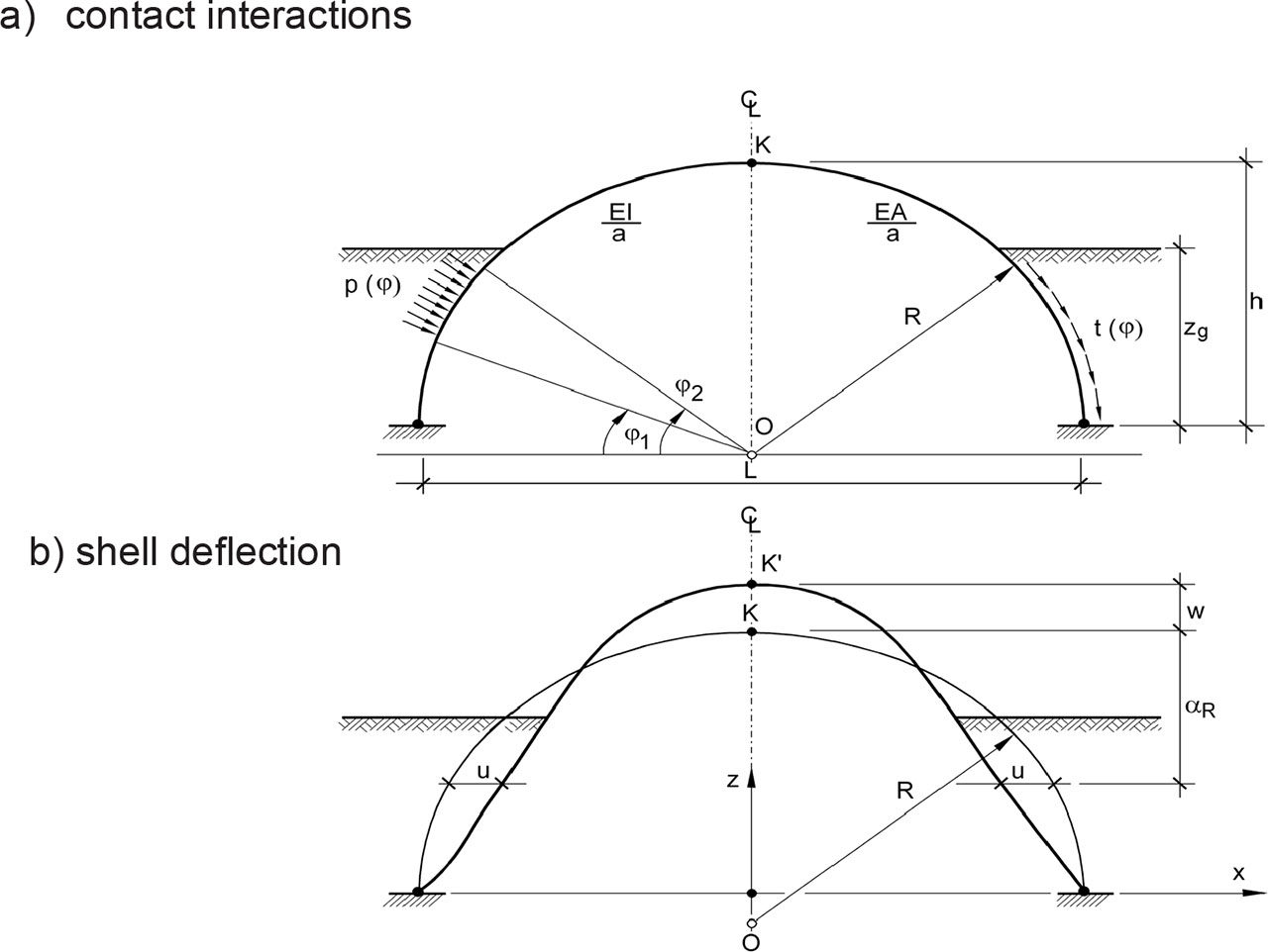
Figure 2:
Scheme of shell deflections and contact forces.
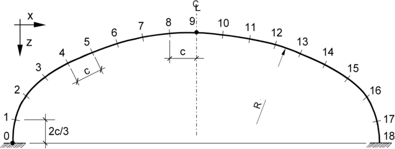
Figure 3:
Scheme of examined structure.
Table 1:
Components of displacements of points No.9 and 11.
| Construction Stage | A | B | C | D | E | F | |
|---|---|---|---|---|---|---|---|
| w (mm) | 9 | 34.7 | 92.3 | 28.8 | −46.8 | −89.4 | −116.3 |
| 11 | 19.6 | −7.9 | −55.2 | −116.9 | −143.2 | −164.7 | |
| u (mm) | 9 | −4.5 | 15.3 | 4.3 | 5.1 | 3.3 | 3.2 |
| 11 | 2.1 | 33.5 | 23.9 | 29.2 | 26.7 | 25.7 | |
| zg(m) | 7.54/7.25 | 9.78/9.99 | 10.44/11.04 | 10.48/11.32 | 11.07/11.92 | 11.73/12.32 | |
| Date | 25.09 | 01.11 | 08.12 | 15.12 | 31.12 | 15.01 | |
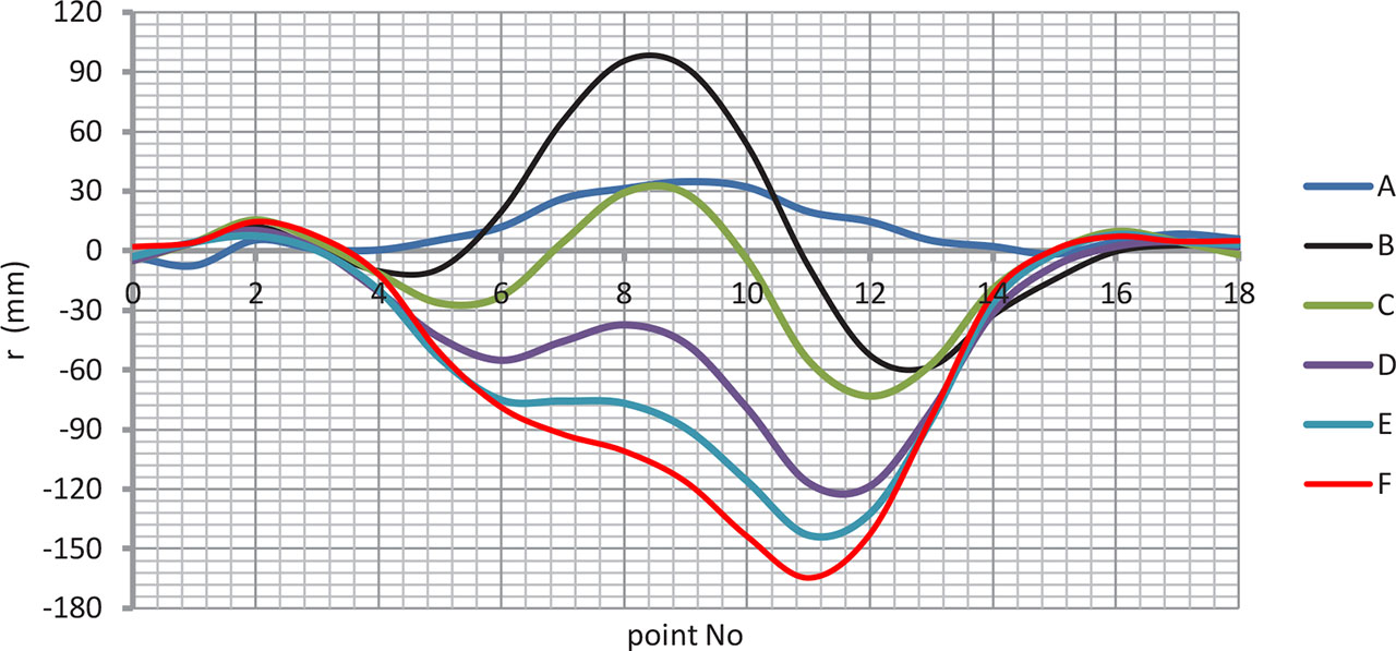
Figure 4:
The steel structure radial displacements functions (analyzed section).
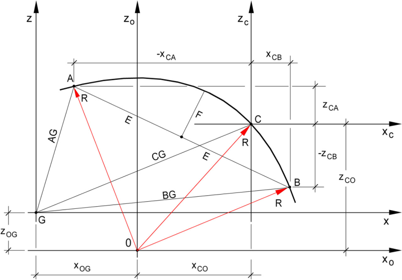
Figure 5:
Calculation scheme of the circumferential section of the shell.
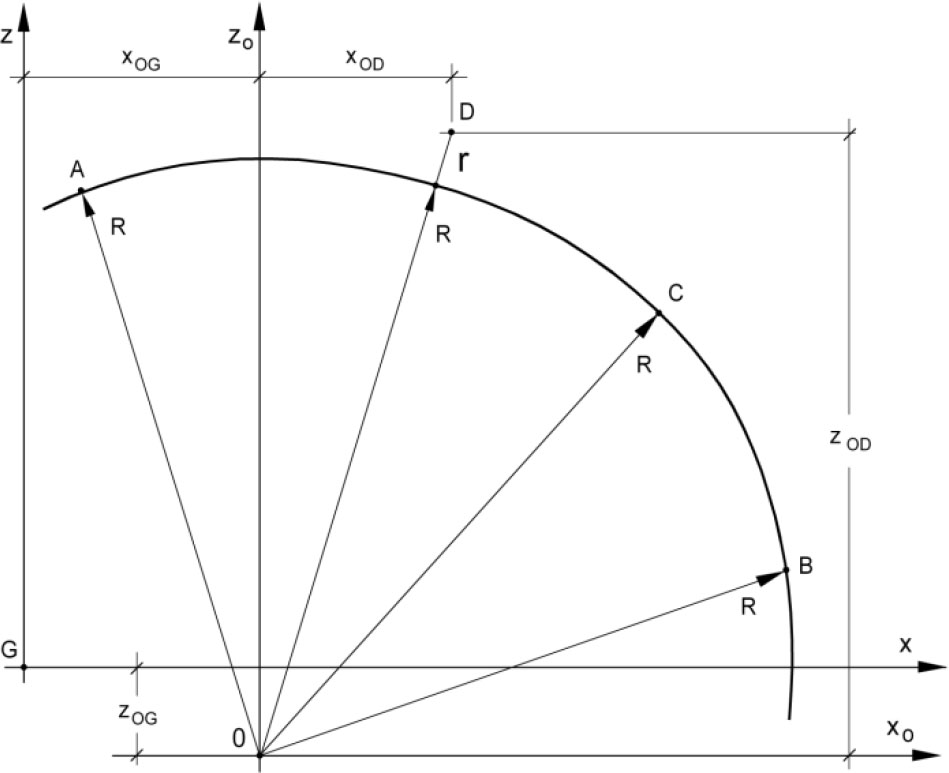
Figure 6:
Correction of coordinates of point D.
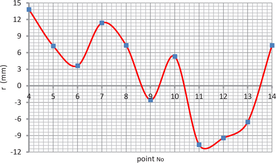
Figure 7:
Correction of the location of measurement points around the structure periphery.
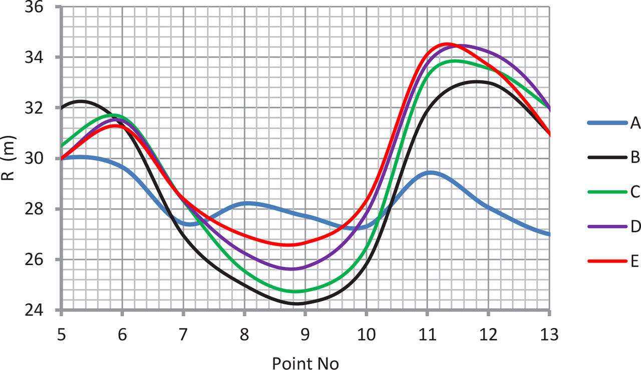
Figure 8:
Changes of radii of curvature near the structure crown point.
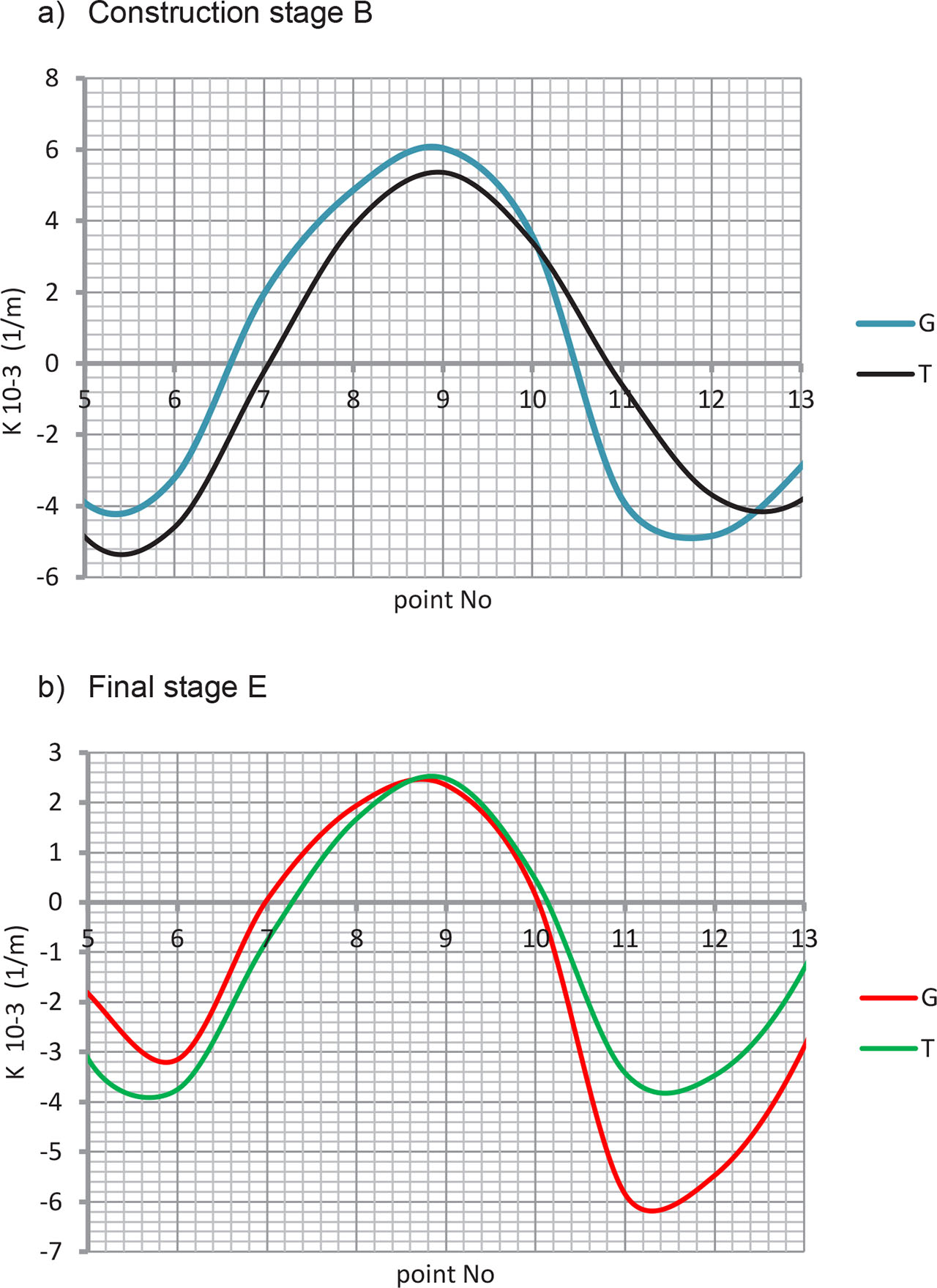
Figure 9:
Changes in curvature along the structure periphery.
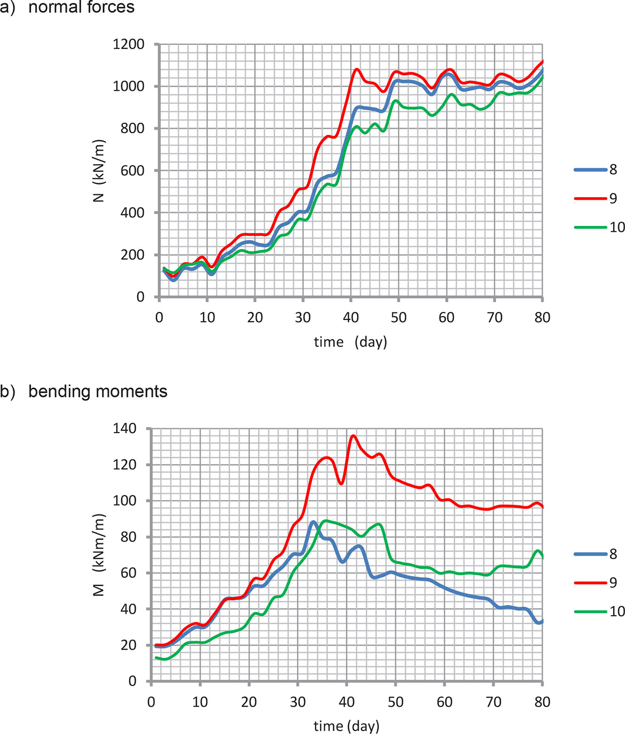
Figure 10:
Changes in internal forces in the area of the structure crown point, obtained from strain gauge measurements.
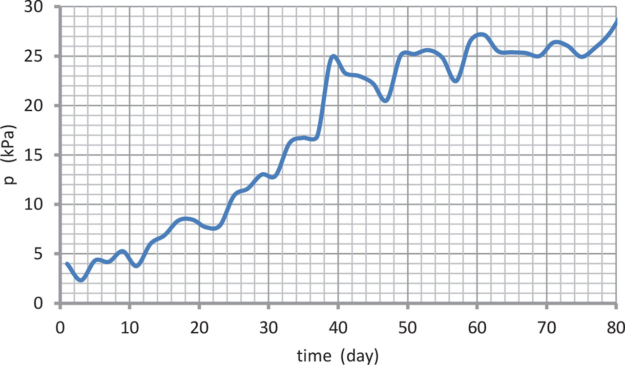
Figure 11:
Changes in soil pressure in the structure crown point.