
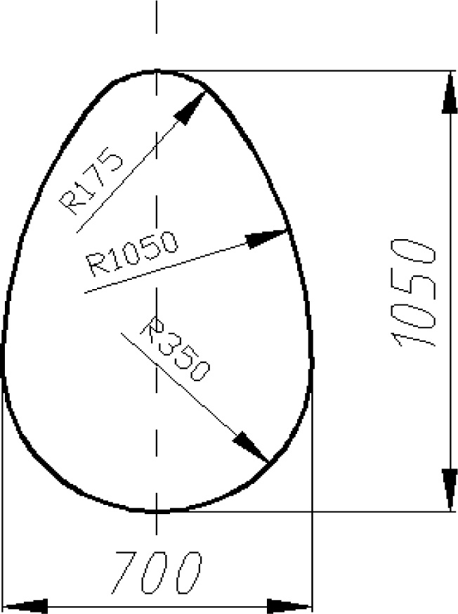
Figure 1
Internal dimensions (in mm) of the conduit's cross section.
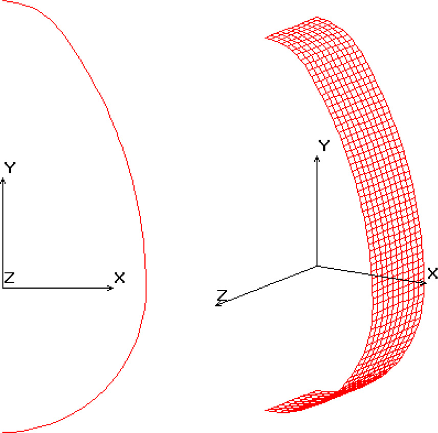
Figure 2
Calculation scheme of the finite element method.
Table 1
Thicknesses of the sleeve calculated for the assumed load cases.
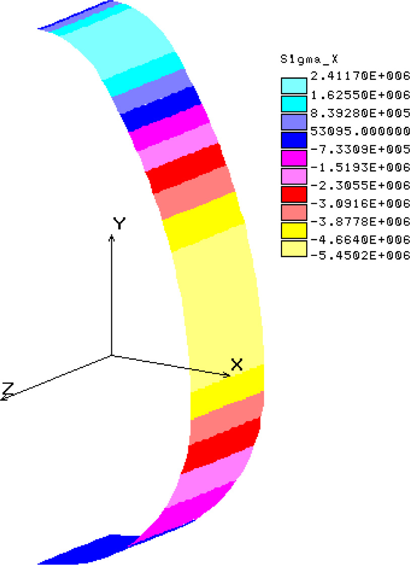
Figure 3
Normal stresses (load scheme 1 – wall thickness equal to 19 mm).
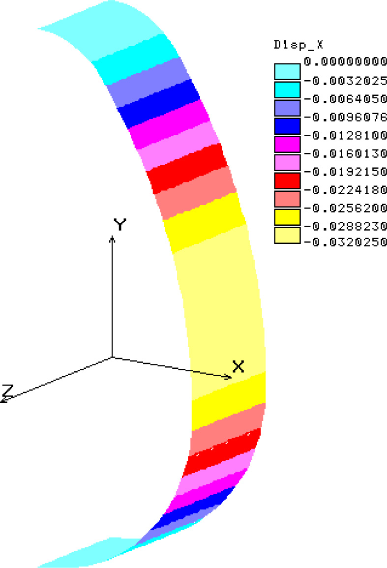
Figure 4
Horizontal displacements (load scheme 1 – wall thickness equal to 19 mm).
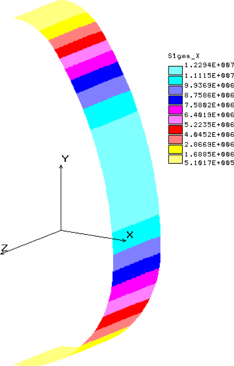
Figure 5
Normal stresses (load scheme 2 – wall thickness equal to 41 mm)
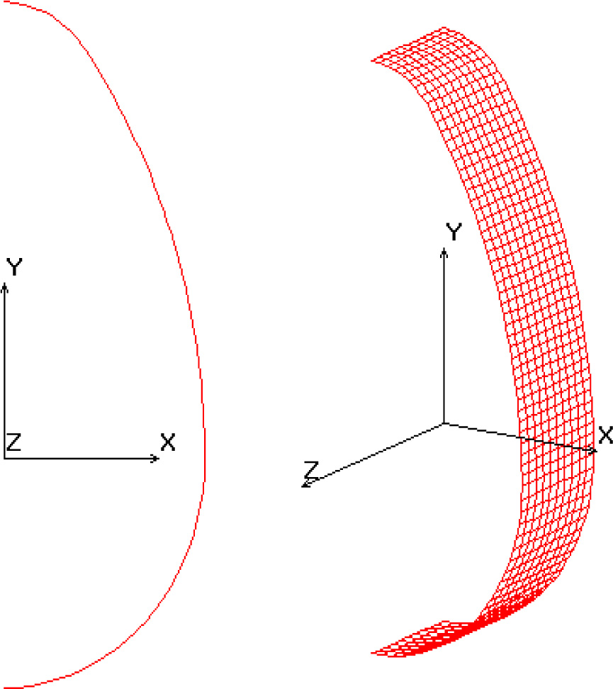
Figure 6
Calculation scheme of the finite element method.
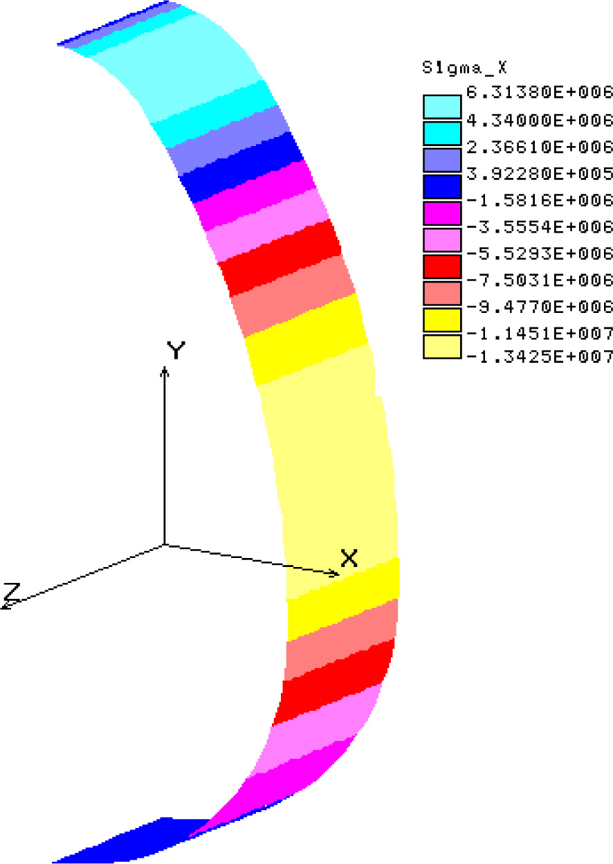
Figure 7
Diagram of normal stresses, wall thickness equal to 12 mm, load scheme 1.
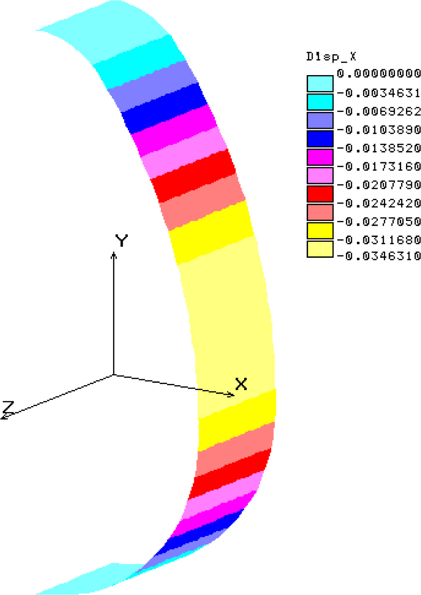
Figure 8
Diagram of horizontal displacements, wall thickness equal to 12 mm, load scheme 1.
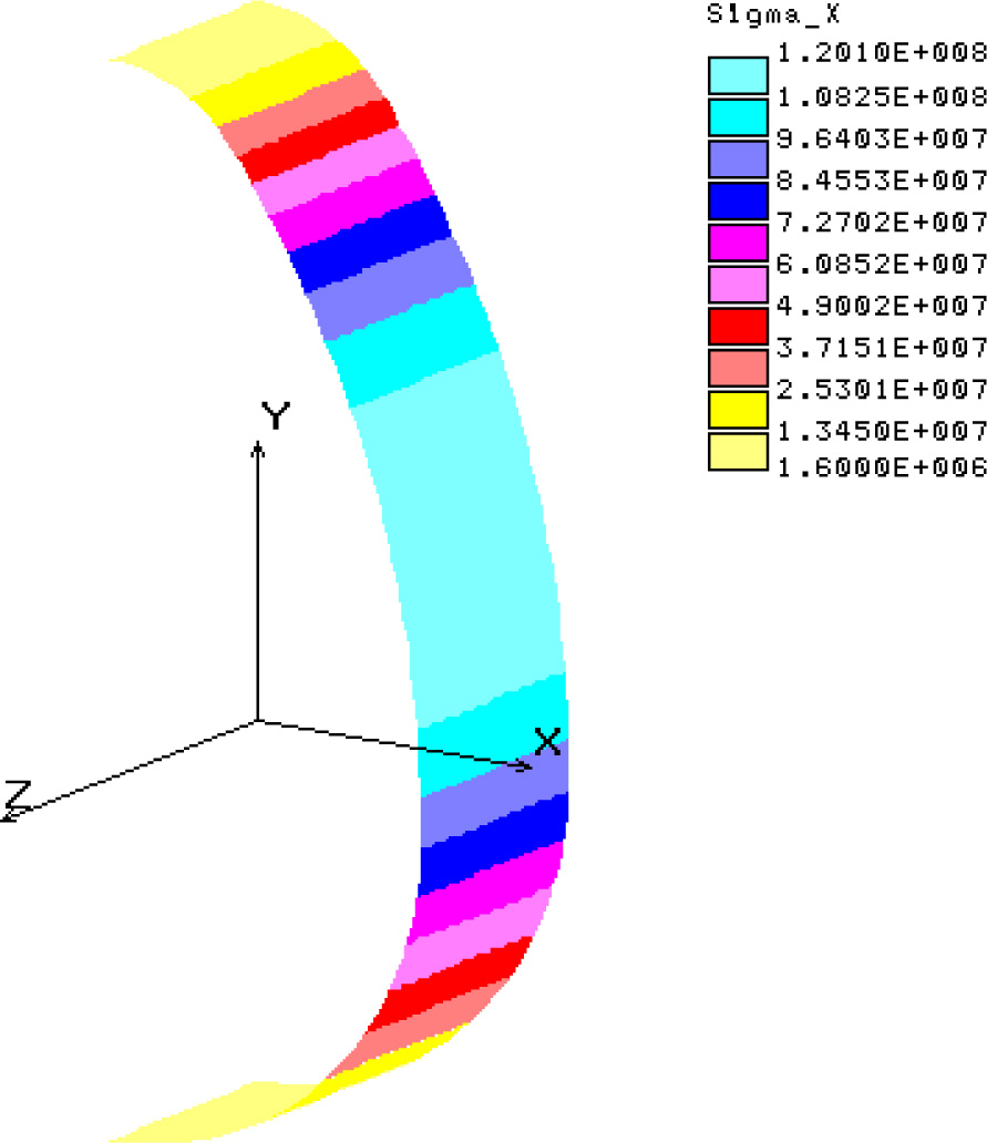
Figure 9
Diagram of normal stresses, wall thickness equal to 13 mm, load scheme 2.