
Table 1
Compositional data of the coal
| Determination | Standard/Method | Weight (%) | Note |
|---|---|---|---|
| Moisture in the Analysis Sample* | ISO 11722:1999 | 11.1 | Air Dried Basis |
| Ash Content* | ISO 1171:2010 (E) | 5.8 | As Received Basis |
| Volatile Matter* | ISO 562:2010 (E) | 37.4 | As Received Basis |
| Fixed Carbon* | By calculation | 42.3 | As Received Basis |
| Carbon** | ASTM D 5373-08 | 65.7 | Air Dried Basis |
| Hydrogen** | ASTM D 5373-08 | 4.4 | Air Dried Basis |
| Nitrogen** | ASTM D 5373-08 | 1.3 | Air Dried Basis |
| Sulphur** | ASTM D 4239-10 | 0.8 | Air Dried Basis |
| Oxygen** | By calculation | 10.7 | Air Dried Basis |
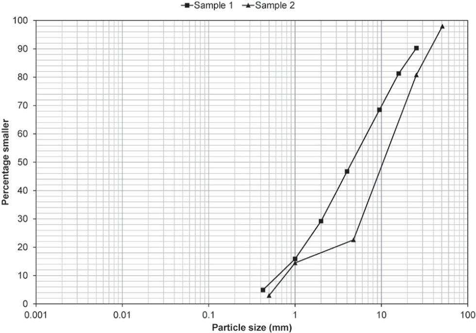
Figure 1
Particle size distribution of two coal samples.
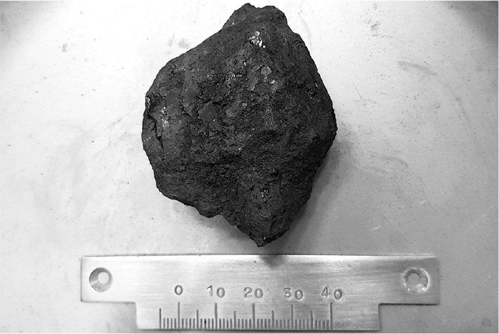
Figure 2
Block of Indonesian Coal subjected to swelling/shrinkage test.
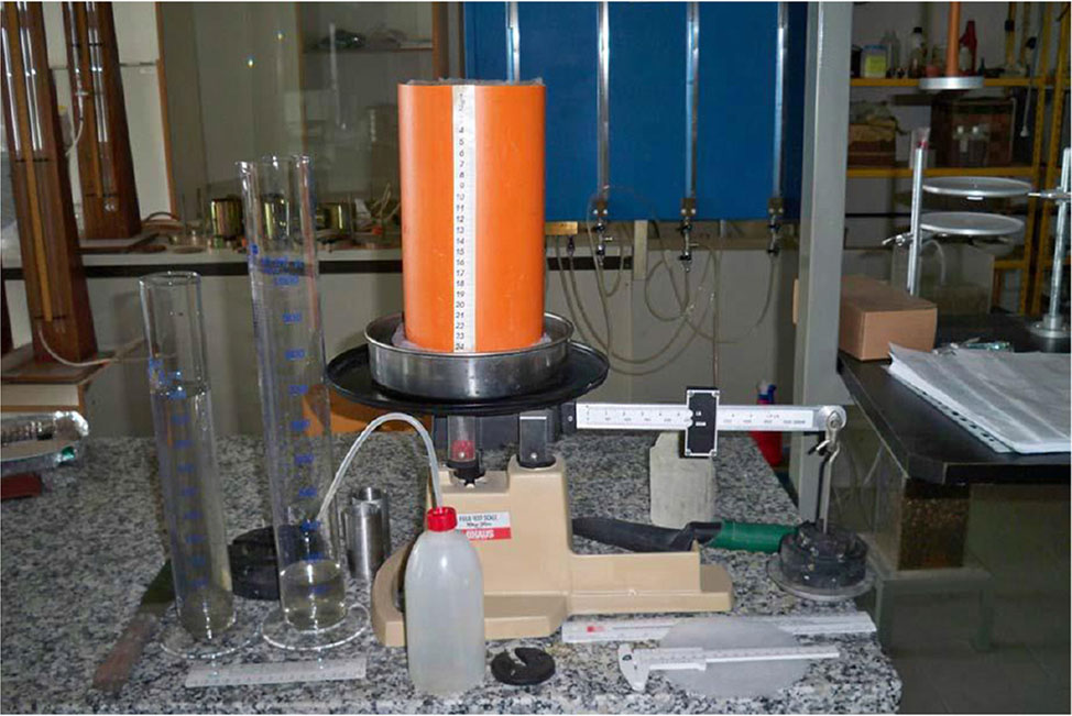
Figure 3
PVC cylindrical cell for the preliminary evaluation of the water retention potential of the coal.
Table 2
Physical-volumetric parameters of the coal cylindrical samples: a) at initial state; b) after imbibition
| a) | ||||||||
|---|---|---|---|---|---|---|---|---|
| Sample | w0 | γ0 (kN/m3) | Gs* | γd (kN/m3) | e0 | Sr | θ | drying procedure / time (day) |
| 1 | 15.9% | 8.4 | 1.2 | 7.2 | 0.63 | 30% | 0.12 | hygroscopic / - |
| 3 | 9.7% | 8.5 | 1.2 | 7.8 | 0.52 | 23% | 0.08 | free drying / 2 |
| 2 | 7.7% | 8.5 | 1.2 | 7.9 | 0.49 | 19% | 0.06 | free drying / 4 |
| 4 | 0.0% | 7.7 | 1.2 | 7.7 | 0.52 | 0% | 0.00 | oven drying at 105°C / 2 |
| b) | |||||||
|---|---|---|---|---|---|---|---|
| Sample | w | γ (kN/m3) | Gs* | γd (kN/m3) | e | Sr | θ |
| 1 | 27.5% | 9.7 | 1.2 | 7.6 | 0.54 | 61% | 0.21 |
| 3 | 26.3% | 10.7 | 1.2 | 8.5 | 0.39 | 81% | 0.23 |
| 2 | 26.8% | 10.5 | 1.2 | 8.2 | 0.43 | 75% | 0.23 |
| 4 | 27.7% | 10.3 | 1.2 | 8.1 | 0.46 | 72% | 0.23 |
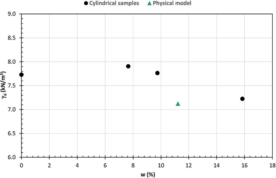
Figure 4
Dry unit weights of coal cylindrical samples and physical model
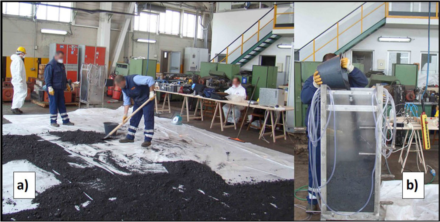
Figure 5
a) View of coal during drying at room temperature; b) phase of prototype filling
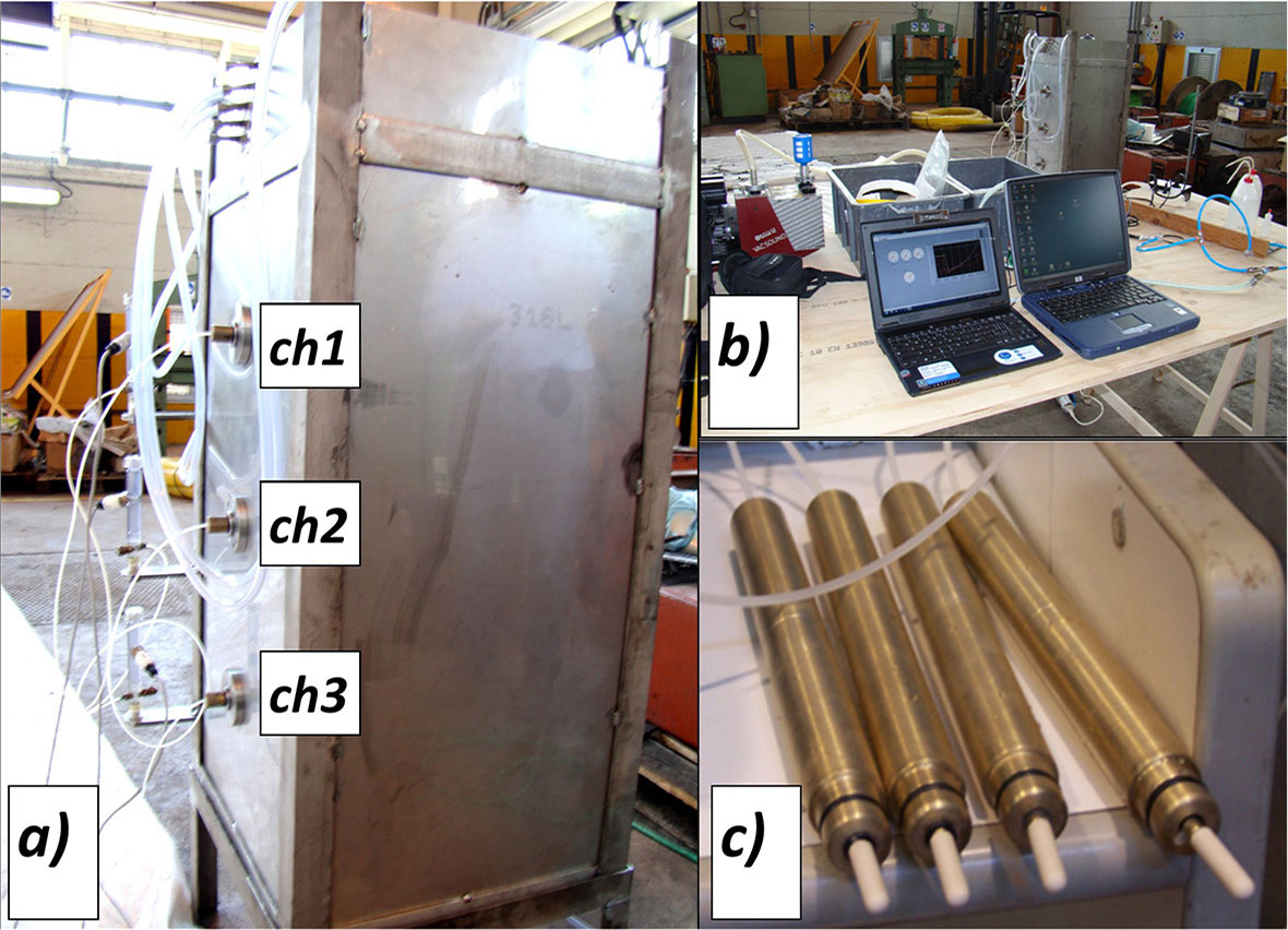
Figure 6
a) Location of the mini-tensiometers; b) continuous data logging system; c) details of the mini-tensiometers
Table 3
Physical-volumetric parameters of the coal in the prototype model: a) at initial state; b) after volumetric collapse
| a) | |||||
|---|---|---|---|---|---|
| w0 | W0 (N) | Wd(N) | H (m) | V (m3) | Gs* |
| 11.21% | 1984 | 1784 | 1.002 | 0.2505 | 1.20 |
| γ (kN/m3) | γd (kN/m3) | e | n | Sr | θ |
| 7.92 | 7.12 | 0.65 | 0.39 | 20.61% | 0.081 |
| b) | |||||
|---|---|---|---|---|---|
| w | W (N) | Wd (N) | H (m) | V (m3) | Gs* |
| 39.87% | 2491 | 1781 | 0.895 | 0.2238 | 1.20 |
| γ (kN/m3) | γd (kN/m3) | e | n | Sr | θ |
| 11.13 | 7.96 | 0.48 | 0.32 | 100% | 0.324 |
Table 4
Matric suction values measured along the central vertical of the prototype model: a) at initial state; b) during the drying phase
| a) | ||
|---|---|---|
| ch1 | ch2 | ch3 |
| (kPa) | (kPa) | (kPa) |
| 61.9 | 56.3 | 65.1 |
| b) | ||
|---|---|---|
| After 7 days of drying at room temperature | ||
| ch1 | ch2 | ch3 |
| (kPa) | (kPa) | (kPa) |
| 2.5 | 2.5 | 2.5 |
| After 14 days of drying at room temperature | ||
| ch1 | ch2 | ch3 |
| (kPa) | (kPa) | (kPa) |
| 15.0 | 15.0 | 15.0 |
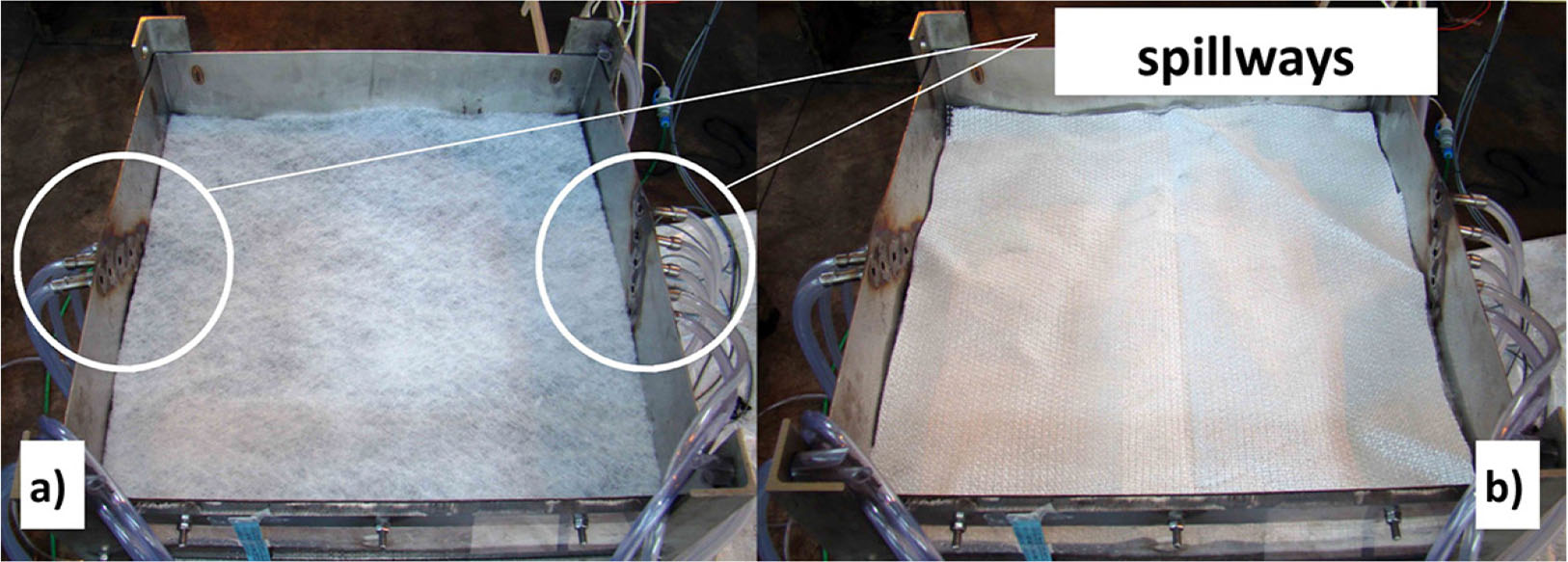
Figure 7
Spillways detail and filtering sheets: a) first layer; b) second layer
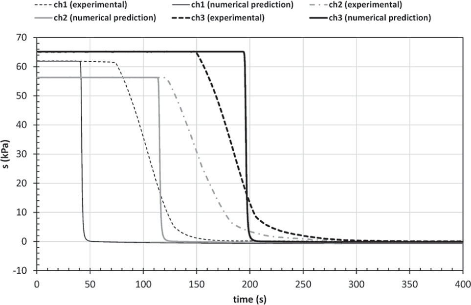
Figure 8
First imbibition phase: experimental data and corresponding numerical results
Table 5
Physical-volumetric state of the coal in the prototype model during the drying phases
| After 7 days of drying at room temperature | |||||
|---|---|---|---|---|---|
| w | W (N) | Wd(N) | H (m) | V (m3) | Gs* |
| 17.70% | 2096 | 1781 | 0.895 | 0.2238 | 1.20 |
| γ (kN/m3) | γd (kN/m3) | e | n | Sr | θ |
| 9.37 | 7.96 | 0.48 | 0.32 | 44.39% | 0.144 |
| After 14 days of drying at room temperature | |||||
| w | W (N) | Wd (N) | H (m) | V (m3) | Gs* |
| 16.73% | 2082 | 1781 | 0.895 | 0.2238 | 1.20 |
| γ (kN/m3) | γd (kN/m3) | e | n | Sr | θ |
| 9.31 | 7.96 | 0.48 | 0.32 | 41.97% | 0.136 |
Table 6
Hydraulic function parameters: a) at the first infiltration test; b) at the second infiltration test
| a) | ||||||
|---|---|---|---|---|---|---|
| θr | θ0 | α | a=1/α | n′ | ks | l |
| (kPa)−1 | (kPa) | (m/s) | ||||
| 0.0165 | 0.3014 | 1.670 | 0.598 | 1.703 | 8.0E-04 | 1 |
| b) | ||||||
|---|---|---|---|---|---|---|
| θr | θ0 | α | a=1/α | n′ | ks | l |
| (kPa)−1 | (kPa) | (m/s) | ||||
| 0.0165 | 0.3014 | 0.812 | 1.231 | 1.703 | 1.0E-05 | 1 |
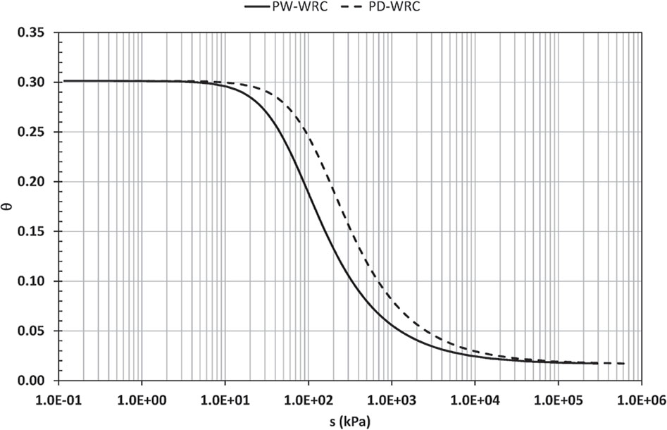
Figure 9
Water retention curves
Table 7
WRC parameters for the drying phase following the first imbibition stage
| θr | θ0 | α | a=1/α | n′ |
|---|---|---|---|---|
| (kPa)−1 | (kPa) | |||
| 0.0165 | 0.3014 | 0.812 | 1.231 | 1.703 |
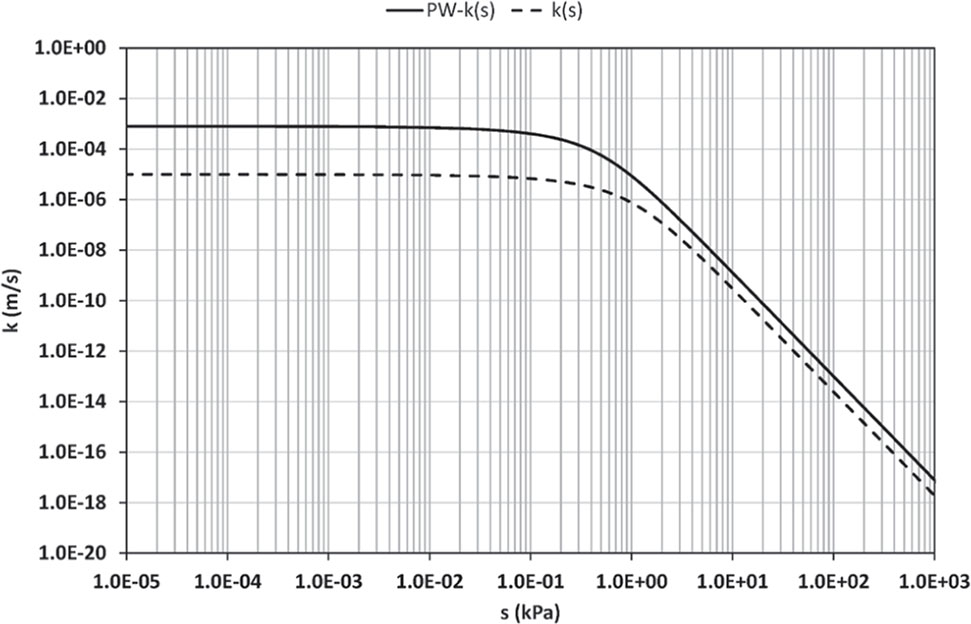
Figure 10
Conductivity functions
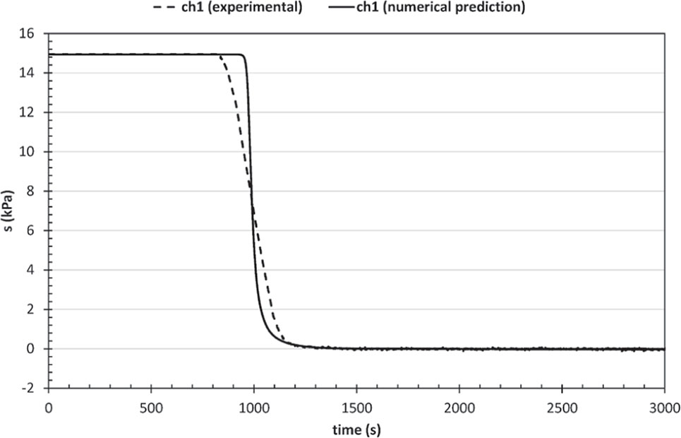
Figure 11
Comparison between measured and predicted variation of suction with time at ch1
Table 8
Hydraulic properties of the Indonesian coal in comparison to other granular materials
| Material | a (kPa) | ks (m/s) |
|---|---|---|
| Indonesian Coal – virgin state (present study) | 0.60 | 8.0E-4 |
| Indonesian Coal – after collapse (present study) | 1.23 | 1.0E-5 |
| Silty Clayey Sand (Cafaro et al. 2008) | 0.63 | 1.58E-6 |
| Pervious Concrete – different mixtures (Marzulli et al. 2018) | 3.07 1.56 | 2E-4 5E-3 |
| Sand (Lu and Likos 2004) | 10 | 3E-4 |
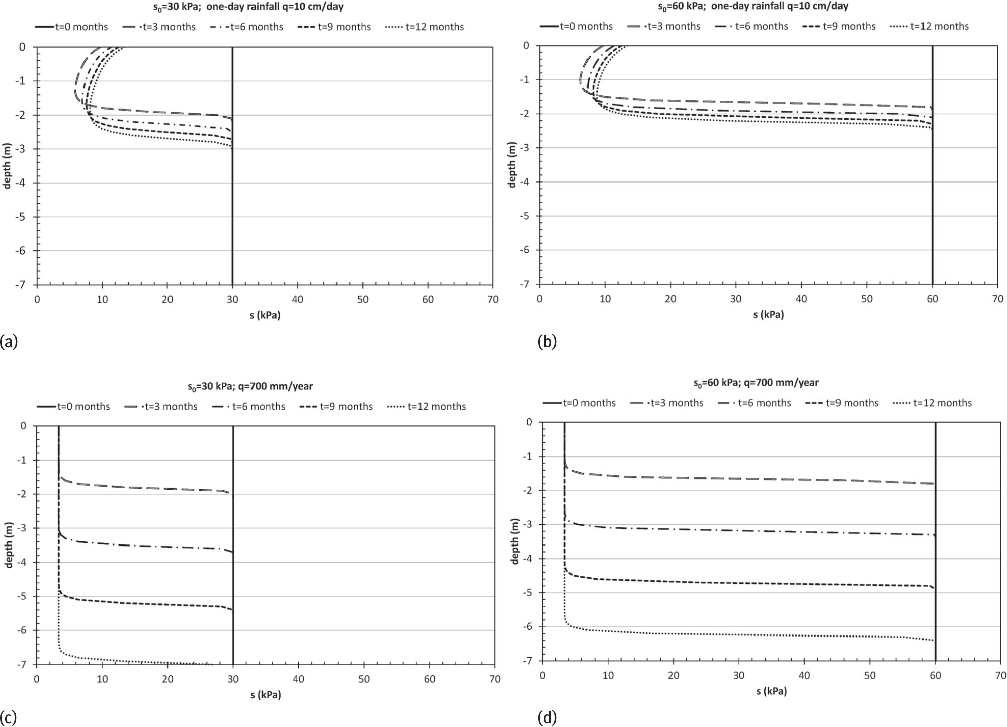
Figure 12
Predicted infiltration due to: (a) an extreme rainfall event through an initially wet stockpile; (b) an extreme rainfall event through an initially dry stockpile; (c) a constant rainfall through an initially wet stockpile; (d) a constant rainfall through an initially dry stockpile.