
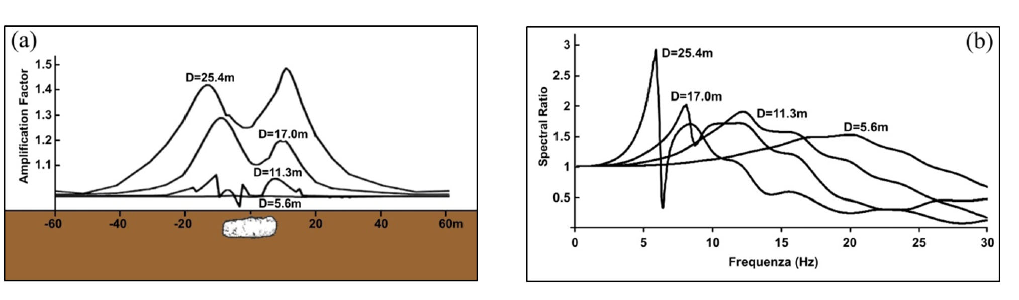
Figure 1
Amplification factor (a) and spectral ratio (b) values above an underground cave inside a homogeneous and isotropic subsoil crossed by Vs waves, based on the parametric variation of the cave diameter (from [7] modified).
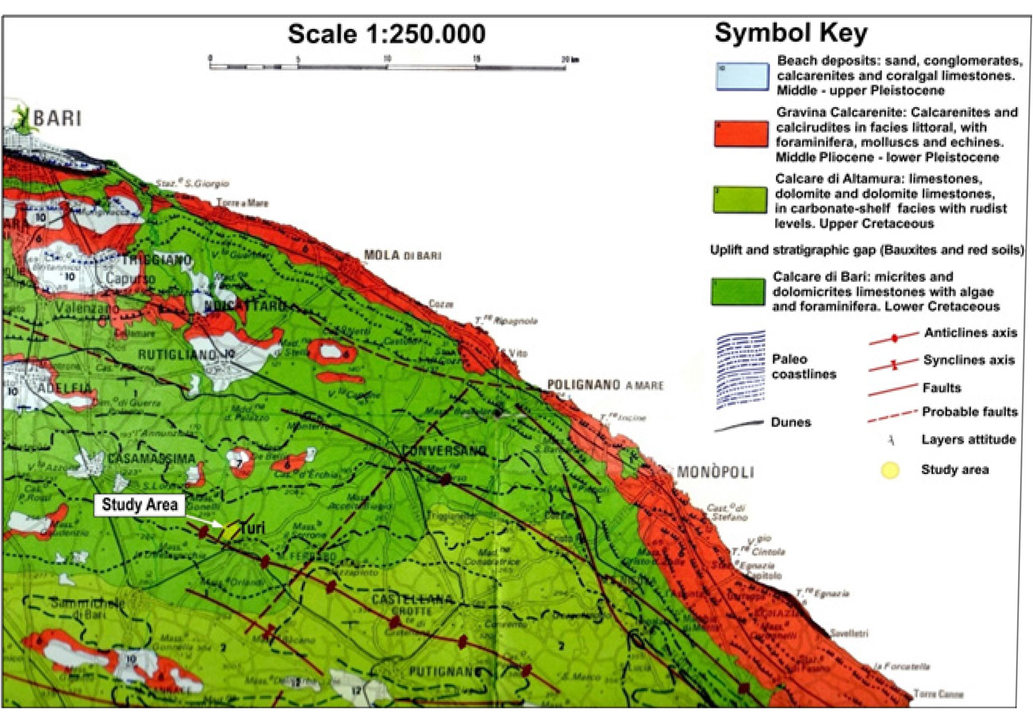
Figure 2
Geological map of the territory in which the study area is located (from [16] modified).
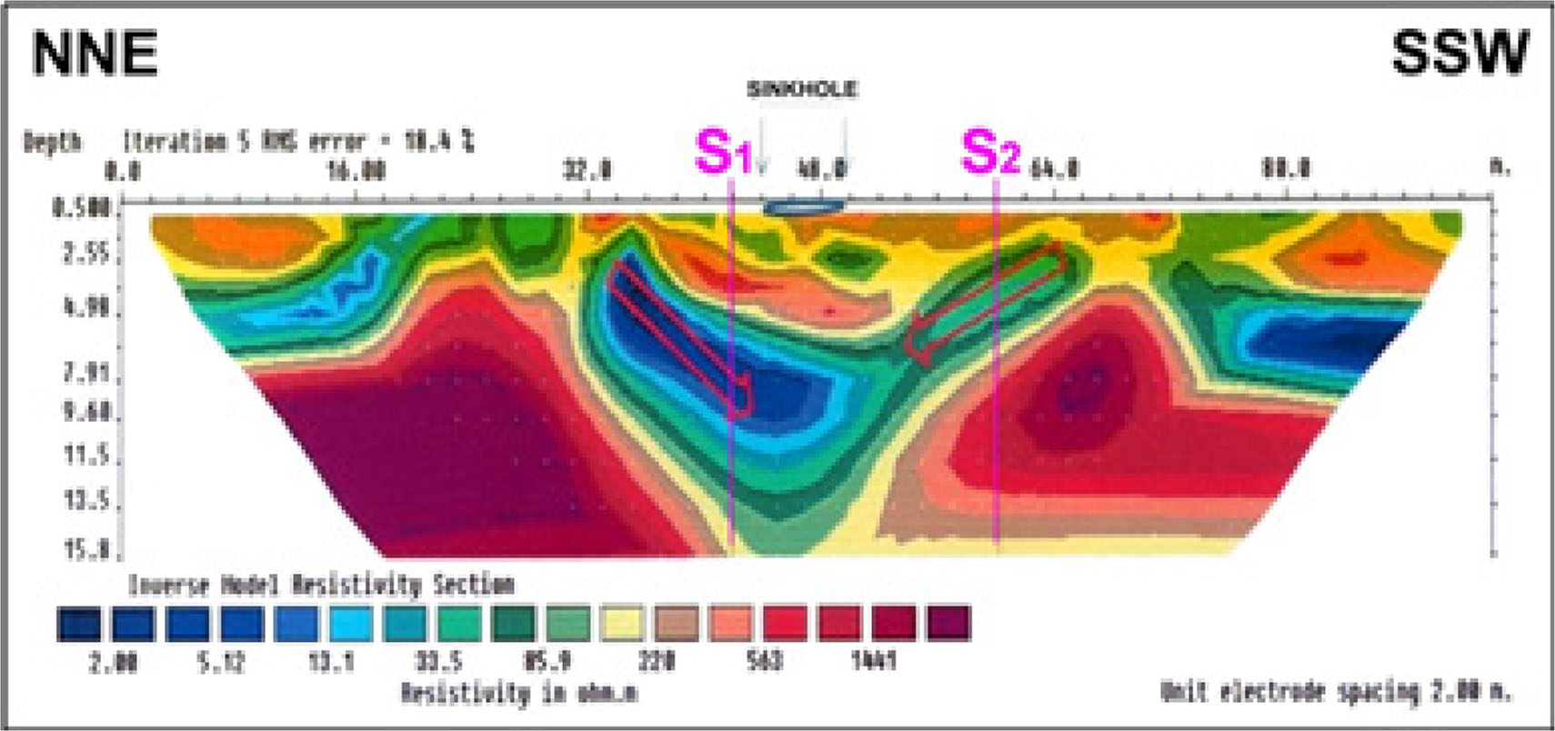
Figure 3
Electric tomography n.1: resistivity values and projection of cores drilling S1 and S2 (from Technical Department of the municipality of Turi (BA) – modified).
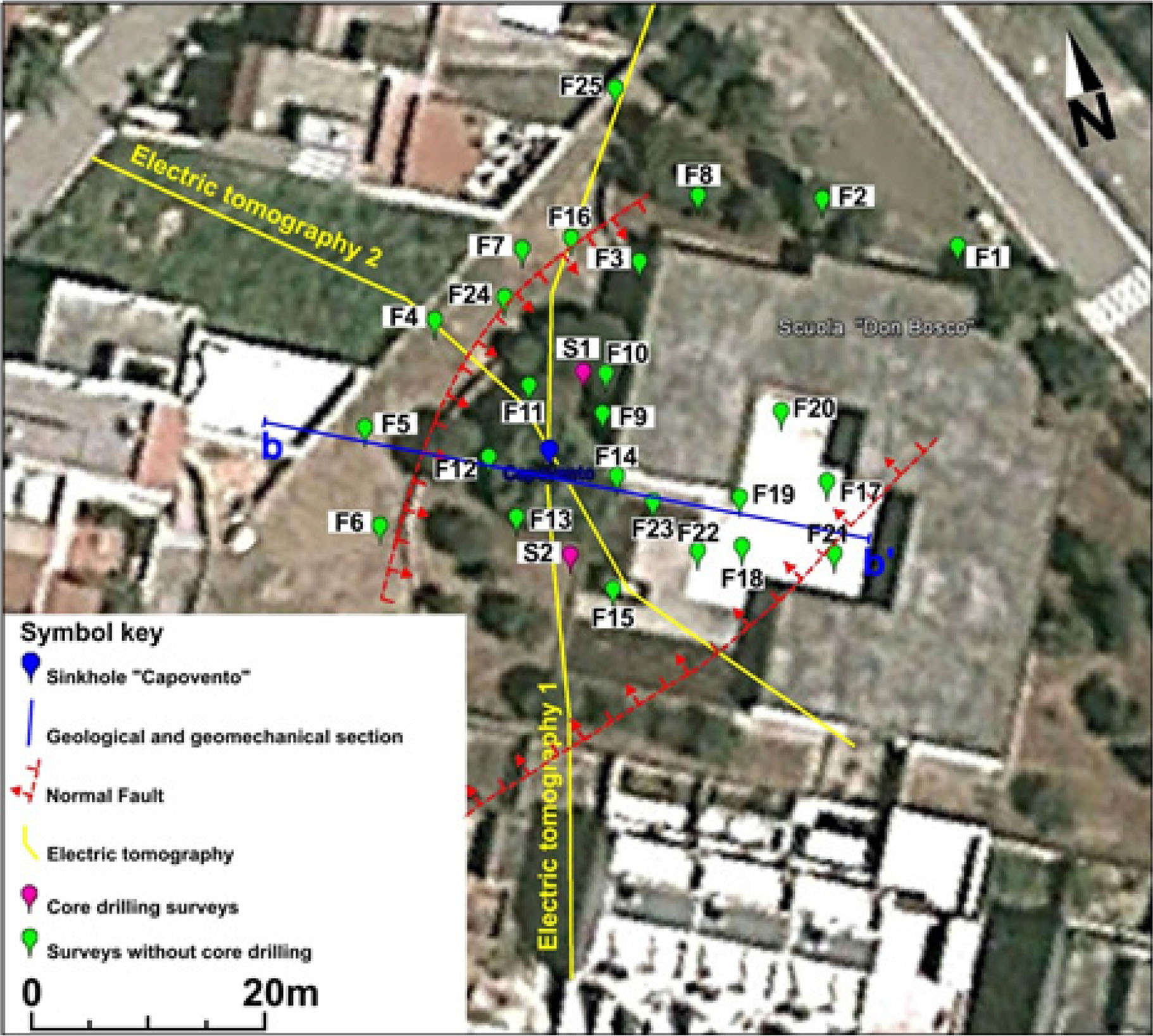
Figure 4
Location of geological surveys and section of the geological and geomechanical model.
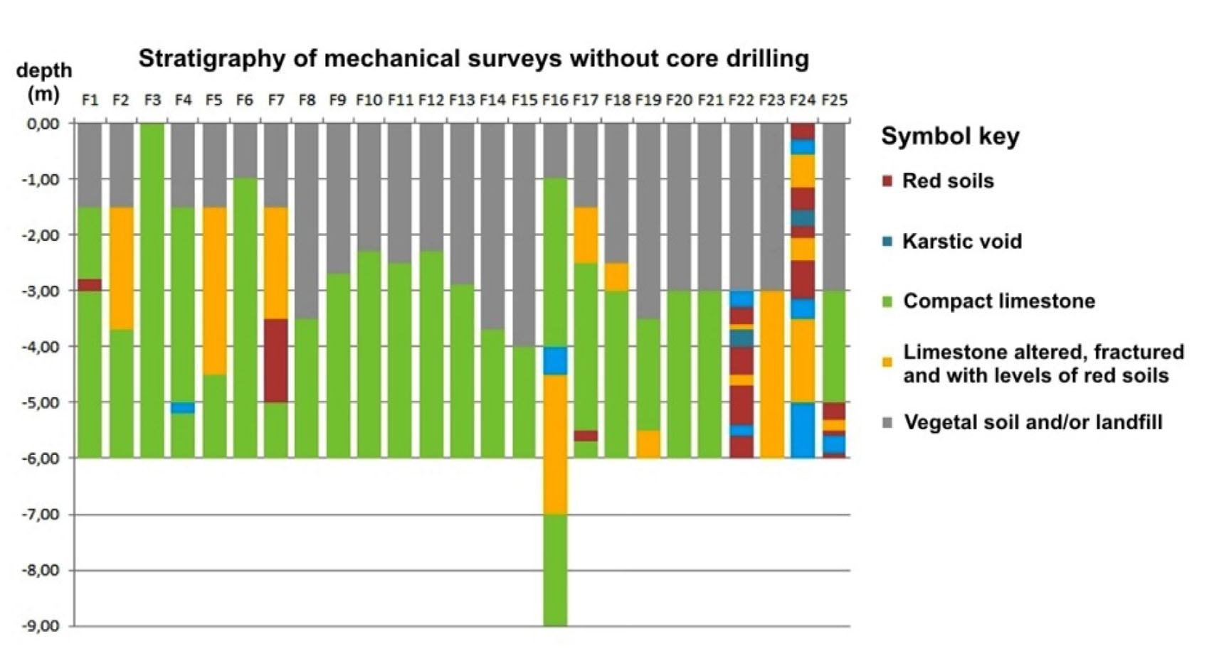
Figure 5
Stratigraphy obtained from the core destruction borings.
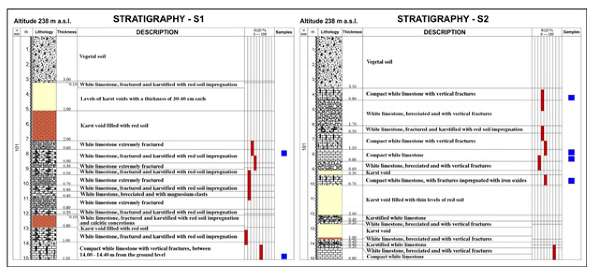
Figure 6
Stratigraphies obtained from rotation drills with continuous coring, RQD trend along verticals and depth of the rock samples for geotechnical laboratory tests.
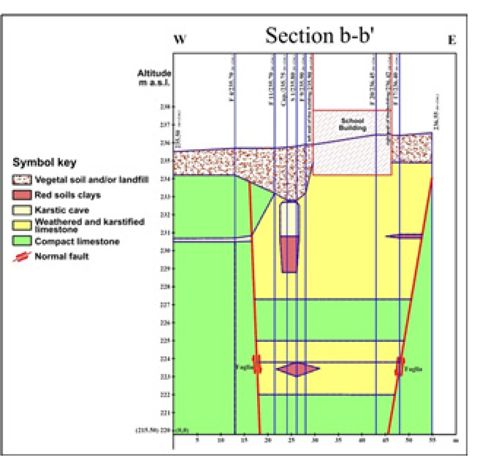
Figure 7
Geomechanical model section used for the LSR evaluation; the upper karst cave has a height of L= 4.00 m and a width of D= 3.00 m.
Table 1
Geomechanical classification of the altered and the compact calcareous rock mass.
| Parameters | Values | RMR'76 | GSI | ||
|---|---|---|---|---|---|
| Rock mass Altered and karstic limestone | R1 (compressive strength) | 7 | 49 | φb = 35° cb = 0.15 MPa | 49 |
| R2 (RQD) | 6 | ||||
| R3 (spacing of discontinuities) | 15 | ||||
| R4 (joint conditions) | 11 | ||||
| R5 (water conditions) | 10 | ||||
| Rock mass Compact and not altered limestone | R1 (compressive strength) | 7 | 62 | φb = 40° cb = 0.20 MPa | 62 |
| R2 (RQD) | 13 | ||||
| R3 (spacing of discontinuities) | 15 | ||||
| R4 (joint conditions) | 17 | ||||
| R5 (water conditions) | 10 |
Table 2
Mechanical parameters of rocks and discontinuities (based on laboratory tests) of the geomechanical model.
| VEGETAL SOIL AND “RED SOILS” | |||||||
|---|---|---|---|---|---|---|---|
| r (Kg/m3) | E (Pa) | v | K (Pa) | G (Pa) | φ (grade) | c (Pa) | σt (Pa) |
| 1835 | 20 · 106 | 0.25 | 13 · 106 | 8 · 106 | 25 | 50000 | 0 |
| ALTERED AND KARSTIC LIMESTONE from laboratory tests | ALTERED ROCK MASS from Hoek-Brown linearized criterion | |||||||||
| r (Kg/m3) | σci (Pa) | σti (Pa) | E (Pa) | v | K (Pa) | G (Pa) | φb (grade) | cb (Pa) | σtb (Pa) | σcb (Pa) |
| 2345 | 58 · 106 | 7 · 106 | 4 · 1010 | 0.20 | 22 · 109 | 17 · 109 | 40 | 0.4 · 106 | 0.2 · 106 | 3 · 106 |
| COMPACT AND NOT ALTERED LIMESTONE from laboratory tests | COMPACT ROCK MASS from Hoek-Brown linearized criterion | |||||||||
| r (Kg/m3) | σci (Pa) | σti (Pa) | E (Pa) | v | K (Pa) | G (Pa) | φb (grade) | cb (Pa) | σtb (Pa) | σcb (Pa) |
| 2345 | 69 · 106 | 8 · 106 | 6 · 1010 | 0.20 | 33 · 109 | 25 · 109 | 50 | 1 · 106 | 0.4 · 106 | 8 · 106 |
| DISCONTINUITY – ALTERED AND KARSTIC LIMESTONE | ||||
| jkn (Pa/m) | jks (Pa/m) | φ (grade) | cj (Pa) | σti (Pa) |
| 1 · 109 | 1 · 108 | 30 | 0.4 · 106 | 0 |
| DISCONTINUITY – COMPACT AND NOT ALTERED LIMESTONE | ||||
| jkn (Pa/m) | jks (Pa/m) | φj (grade) | cj (Pa) | σti (Pa) |
| 1.2 · 109 | 1 · 108 | 35 | 0.4 · 106 | 0 |
| NORMAL FAULT | ||||
| jkn (Pa/m) | jks (Pa/m) | φj (grade) | cj (Pa) | σti (Pa) |
| 1.2 · 109 | 1 · 108 | 60 | 0.4 · 106 | 0 |
Table 3
Relevant input data for the accelerograms search with the REXEL 3.5 software.
| Target Spectrum | ag (g) | Geographic Coordinates ED50 | Site class | Topographic category | Nominal Life | Functional Type | Limit State | M | R (km) | |
|---|---|---|---|---|---|---|---|---|---|---|
| Lat. N | Long. E | |||||||||
| Italian Building Code 2008 | 0.074 | 17.0222 | 40.9185 | A | T1 | 50 years | III | SLV | 6–7 | 0–100 |
Table 4
Main data of the seismic events extracted from the database for the X-acceleration (above) and the Z-acceleration (below).
| Waveform ID | Earthquake ID | Station ID | Earthquake Name | Date | Mw | Fault Mechanism | Epicentral Distance (km) | EC8 Site class |
|---|---|---|---|---|---|---|---|---|
| 286 | 146 | ST92 | Campano Lucano | 11/23/1980 | 6.9 | normal | 78 | A |
| Waveform ID | Earthquake ID | Station ID | Earthquake Name | Date | Mw | Fault Mechanism | Epicentral Distance (km) | EC8 Site class |
|---|---|---|---|---|---|---|---|---|
| 172 | 81 | ST48 | Basso Tirreno | 04/15/1978 | 6 | oblique | 58 | A |
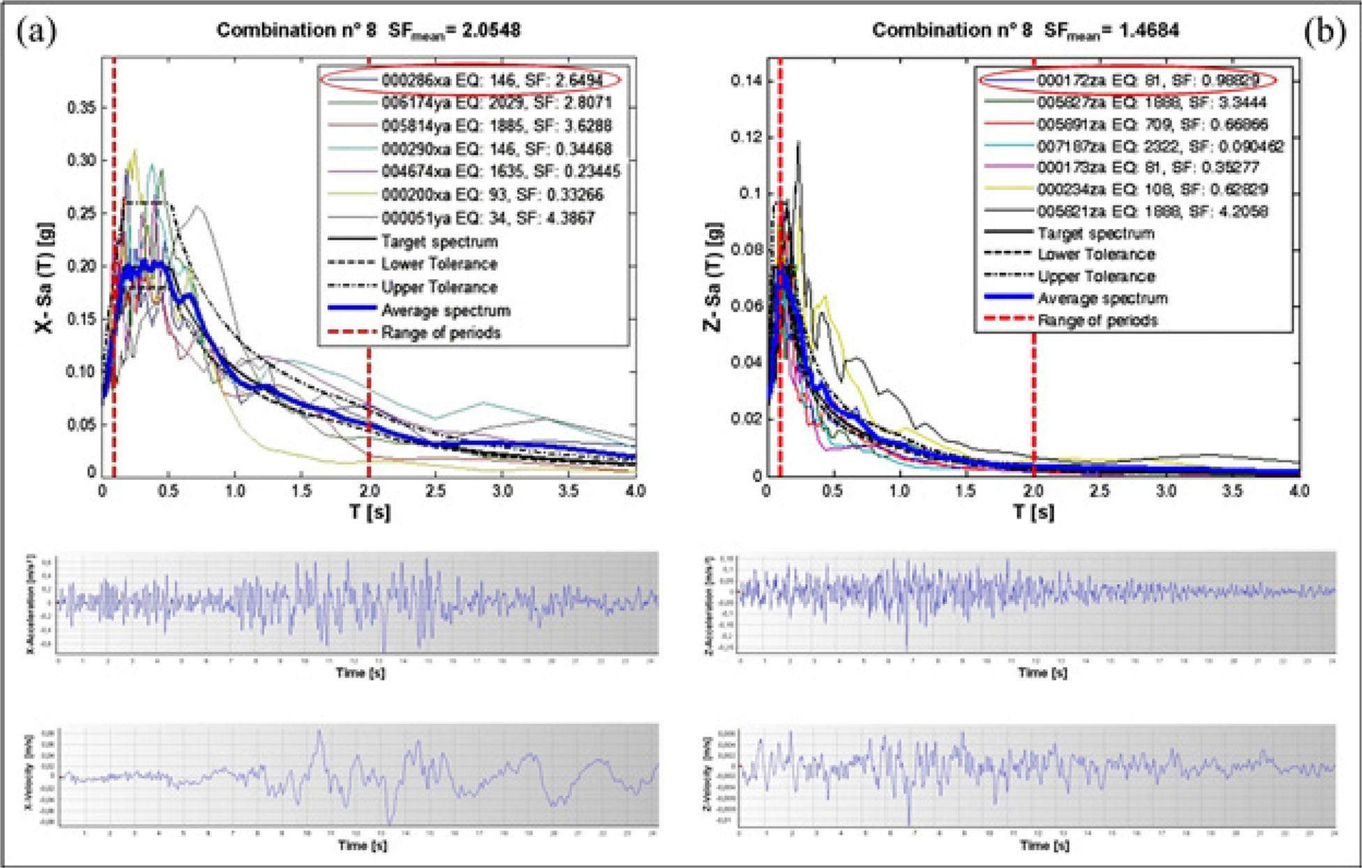
Figure 8
Acceleration–period spectrums of the combinations no 8 and accelerogram/velocity time–history of the two earthquakes chosen (red circled) for the LSR analysis: X-component (a) and Z-component (b).
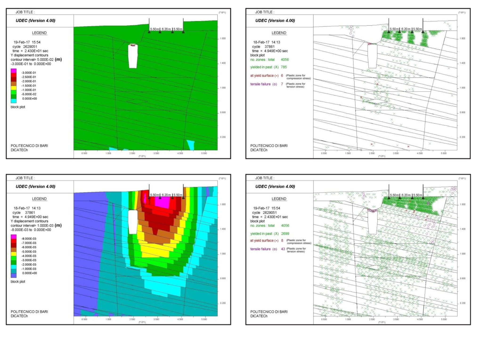
Figure 9
Trend of displacements in the Y-direction (left) and plastic zones (right) in the geomechanical model with two overlapping underground caves: in static (above) and dynamic (below) conditions.
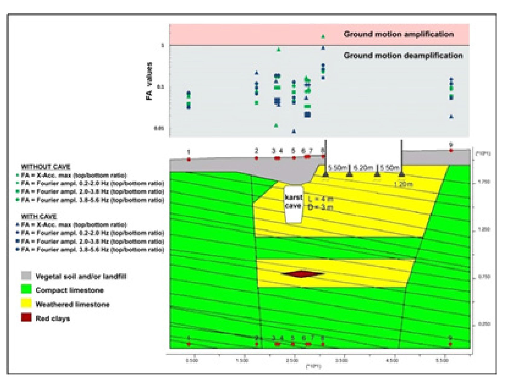
Figure 10
LSR amplification/deamplification, as X-accelerations FA, in each of the control points at the ground level of case study model.
Table 5
FA, calculated in the absence and presence of karst caves, as ratio of the maximum X-acceleration and ratio of the Fourier’s amplitudes spectrum in three ranges of frequency.
| Output Point ID | ||||||||
|---|---|---|---|---|---|---|---|---|
| Without caves | With caves | Without caves | With caves | Without caves | With caves | Without caves | With caves | |
| 1 | 0.060 | 0.033 | 0.067 | 0.039 | 0.072 | 0.033 | 0.065 | 0.032 |
| 2 | 0.084 | 0.221 | 0.120 | 0.043 | 0.122 | 0.097 | 0.118 | 0.070 |
| 3 | 0.012 | 0.129 | 0.161 | 0.090 | 0.176 | 0.048 | 0.171 | 0.040 |
| 4 | 0.730 | 0.036 | 0.161 | 0.090 | 0.176 | 0.048 | 0.171 | 0.040 |
| 5 | 0.048 | 0.009 | 0.098 | 0.071 | 0.123 | 0.040 | 0.119 | 0.053 |
| 6 | 0.169 | 0.057 | 0.079 | 0.035 | 0.113 | 0.021 | 0.142 | 0.024 |
| 7 | 0.093 | 0.024 | 0.079 | 0.035 | 0.113 | 0.021 | 0.142 | 0.024 |
| 8 | 1.672 | 0.899 | 0.259 | 0.272 | 0.274 | 0.172 | 0.236 | 0.342 |
| 9 | 0.120 | 0.019 | 0.093 | 0.058 | 0.143 | 0.052 | 0.084 | 0.113 |