
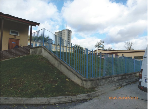
Figure 1
The outside view of water tank.
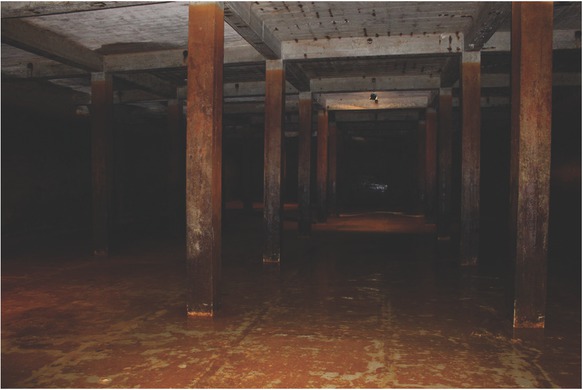
Figure 2
The interior of concrete tank.
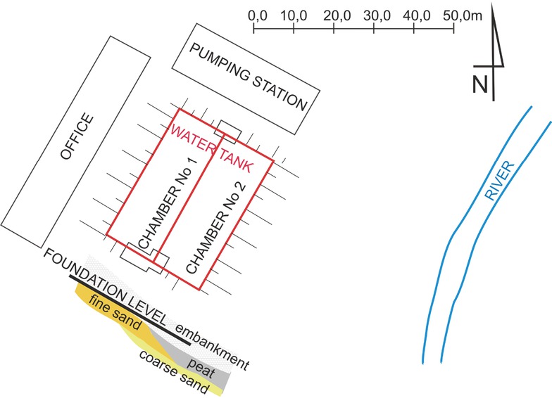
Figure 3
The location of water tank in relation to the river and the buildings of water supply plant with the scheme of geotechnical layers.
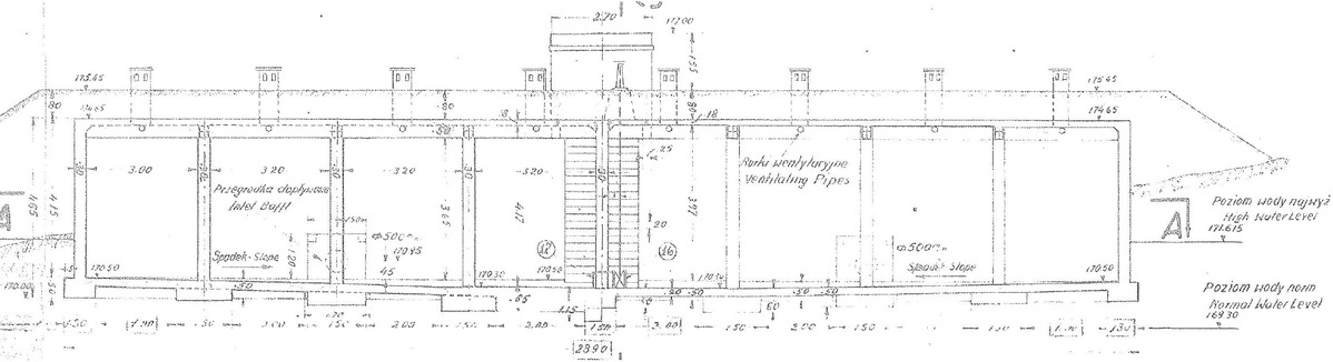
Figure 4
The original design drawing of tank cross section [1].
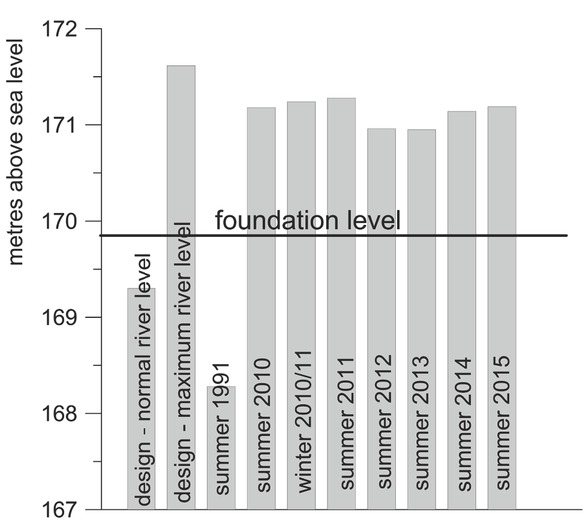
Figure 5
The levels of underground water in relation to foundation level: the water in the river in accordance to design drawings (normal and maximum) and the water level found nowadays (maximum).
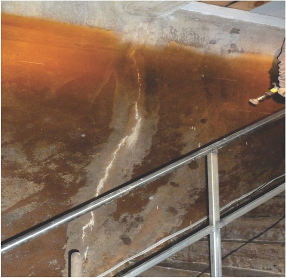
Figure 6
The exemplifying crack with salting out in the longitudinal partition wall.
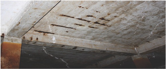
Figure 7
The exemplifying crack with stalactites of salting out in the roof slab.
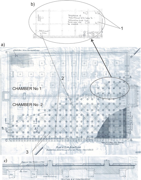
Figure 8
Original design drawings concerning the tank strengthening [1]: (a) location of piles in the ABCD region, (b) hand-made remarks, (c) cross section of bottom slab with concrete piles; (1) location of holes planed for peat level determination, (2) ‘additional piles’ (probably timber piles), (3) concrete piles under foundation slab.
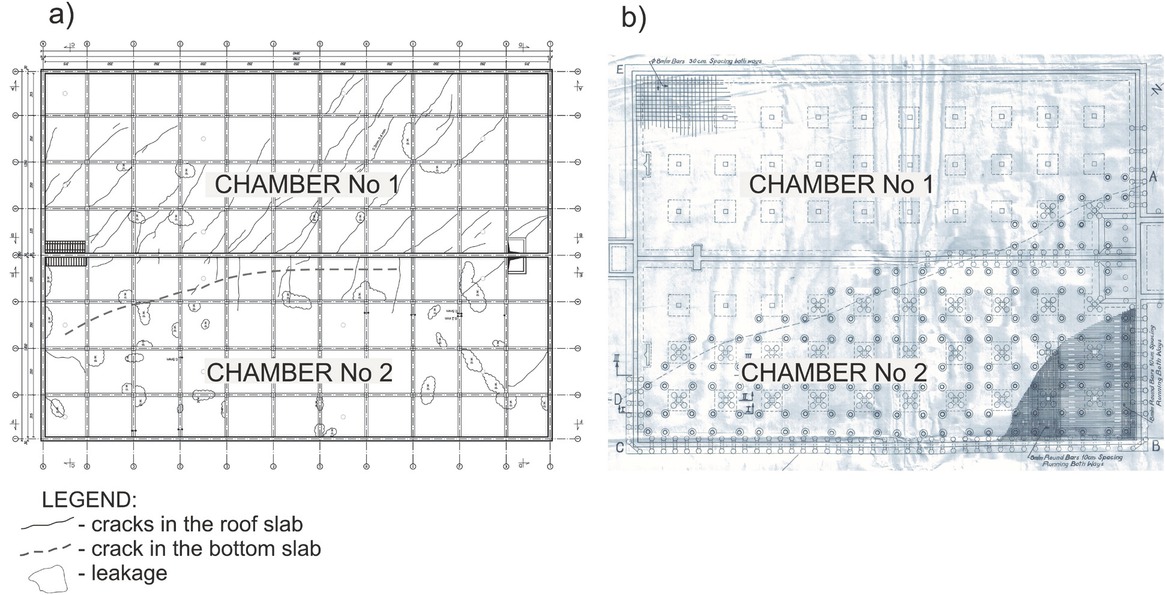
Figure 9
Crack pattern (a) versus region with piles (b).
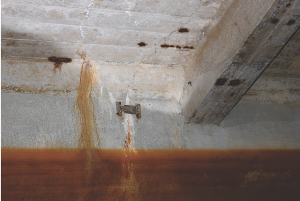
Figure 10
The crack width gauge fixed to the longitudinal partition wall.
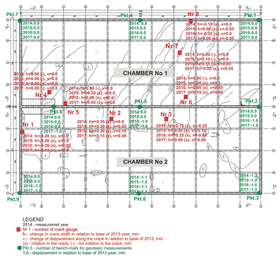
Figure 11
The location of crack gauges and places of vertical displacement surveying and the measurement results in 2014–2017.
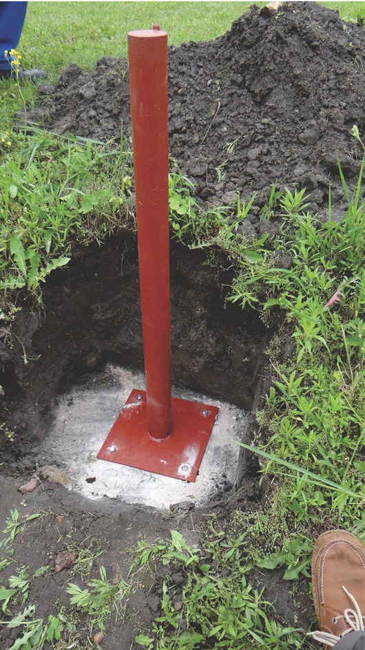
Figure 12
The structure of controlled point whilst fixing to the upper surface of the roof slab.
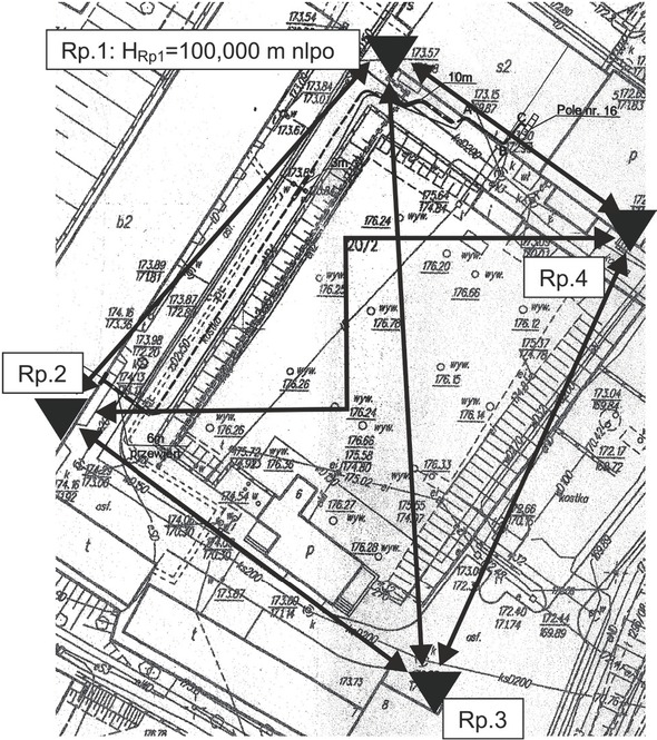
Figure 13
The benchmark control levelling network.
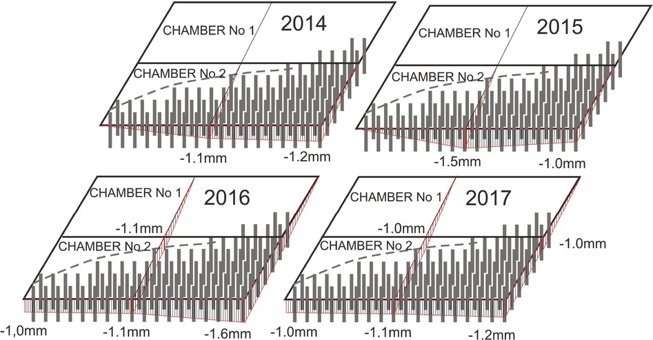
Figure 14
Displacement of controlled points.