
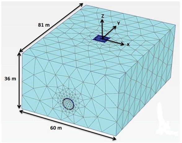
Figure 1
3D finite element meshes, dimensions of problem and axis location used in the analysis.
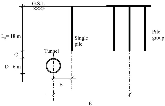
Figure 2
Underground location of tunnel relative to a single and group of piles.
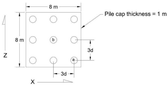
Figure 3
Piles cap dimension and Locations of piles in groups.
Table 1
Concrete parameters adopted in the numerical analysis.
| Parameters | Values | Units | Model | |||
|---|---|---|---|---|---|---|
| Pile | Pile cap | Tunnel lining | TBM shield | |||
| Diameter (D) | 1 | - | - | - | m | Linear |
| Thickness (t) | - | 1 | 0.25 | 0.35 | m | elastic |
| Elasticity modulus (E) | 30×106 | 30×106 | 30×106 | 210×106 | ||
| Unit weight (γ) | 25 | 25 | 25 | 38 | ||
| Possion’s ratio (ѵ) | 0.2 | 0.2 | 0.2 | 0.3 | - | |
Table 2
Soil parameters adopted in the numerical analysis (from Miro et al. 2012).
| Soil Parameters HS model | ||
|---|---|---|
| Parameters | values | units |
| Friction angle, φ | 35 |  |
| Dilatancy angle, Ψ | 5 |  |
| Cohesion, c | 10 | [kN/m2] |
| Secant stiffness in the standard drained triaxial test, | 35000 | [kN/m2] |
| Tangent stiffness for primary oedometer loading, | 35000 | [kN/m2] |
| Unloading and reloading stiffness, | 100000 | [kN/m2] |
| Reference pressure, pref | 100 | [kN/m2] |
| Power for stress-level dependency of stiffness, m | 0.7 | [-] |
| Failure ratio, Rf | 0.9 | [-] |
| Poisson’s ratio for unloading-reloading,Ѵur | 0.2 | [-] |
| Soil weight above phreatic level, γunsat | 17 | [kN/m3] |
| Soil weight below phreatic level, γsat | 20 | [kN/m3] |
| Strength reduction factor for interfaces in | 0.6 | [-] |
| PLAXIS, Rinter |
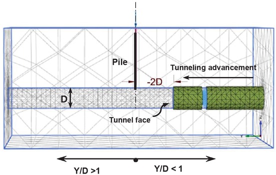
Figure 4
The zone of infuence in longitudenal direction.
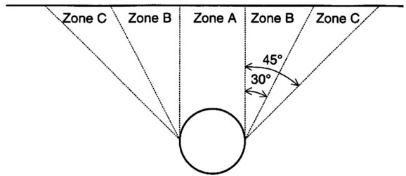
Figure 5
Zones of pile movement around a tunnel driven through soft clays and dense sands after the Heinenoord full-scale trial (Kaalberg et al. 1999).
Table 3
Analysis series for a single and group of piles with different offset ratio (E/D)
| Single pile | Pile group (3×3) | |||||||||
|---|---|---|---|---|---|---|---|---|---|---|
| Analysis series | I | II | III | IV | V | VI | VII | VIII | IX | X |
| C/D | 0.16 | 0.16 | 0.16 | 0.16 | 0.16 | 0.16 | 0.16 | 0.16 | 0.16 | 0.16 |
| E/D | 0 | 0.5 | 1.0 | 1.5 | 2.0 | 0 | 0.5 | 1.0 | 1.5 | 2.0 |
Table 4
Analysis series for a single and group of piles with different depth ratio (C/D).
| Single pile | Pile group (3×3) | |||||||||
|---|---|---|---|---|---|---|---|---|---|---|
| Analysis series | XI | XII | XIII | XIV | XV | XVI | XVII | XVIII | XIX | XX |
| C/D | 0.16 | 0.5 | 0.75 | 1.0 | 2.0 | 3.0 | 0.16 | 0.5 | 0.75 | 1.0 |
| E/D | 0 | 0 | 0 | 0 | 0 | 0 | 0 | 0 | 0 | 0 |
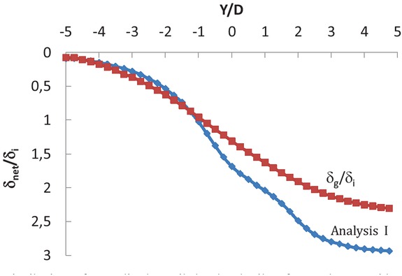
Figure 6
Distributions of normalized net pile head and soil surface settlement with tunnel advancement for single pile.
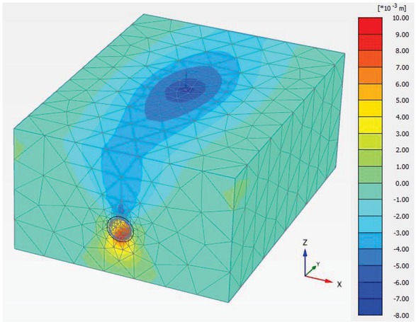
Figure 7
Displacement of soil at the end of excavation Y/D= +5. (Analysis I).
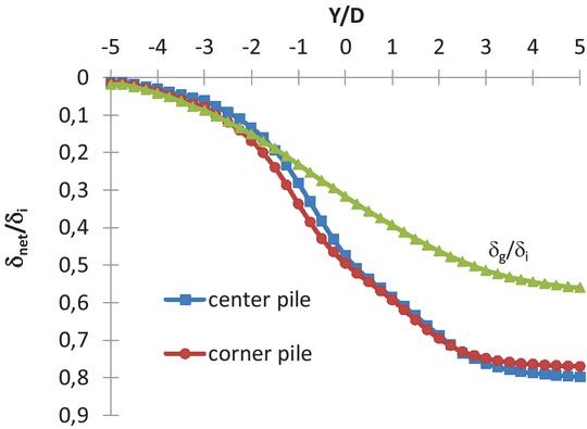
Figure 8
Distributions of normalized net pile head and soil surface settlement with tunnel advancement for group pile 3 x 3 (analysis IV and G).
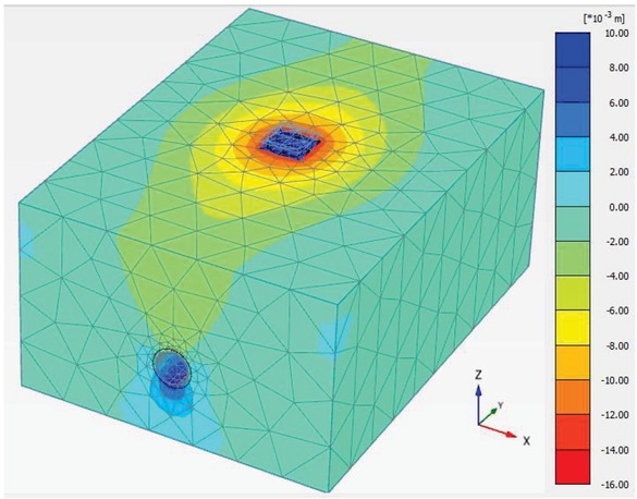
Figure 9
Soil displacement at the end of tunnel excavation Y/D= +5. (analysis VI).
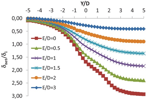
Figure 10
Variations of pile head settlement during tunnelling process for various E/D (analysis series I, II, III, IV, and V).
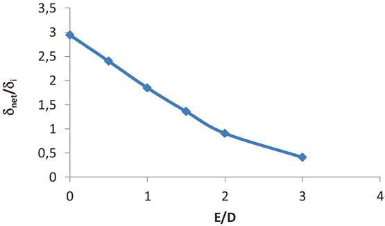
Figure 11
Variation of normalized net pile head settlement with E/D at the end of tunnel excavation (Y/D= +5).
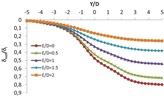
Figure 12
Variations of center pile head settlement at (3 x 3) piles group during tunnelling process for various E/D.
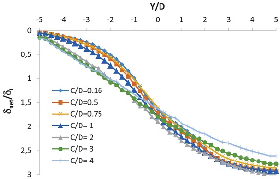
Figure 13
Distributions of normalized net pile head settlement with tunnel advancement for various C/D (single pile).
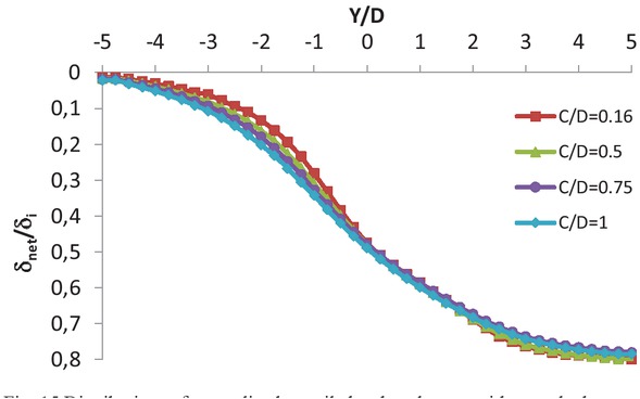
Figure 15
Distributions of normalized net pile head settlement with tunnel advancement for various C/D (group of piles). Analysis series (XV, XVI, XVII, and XVIII).
Table 5
Analysis series for a single and group of piles with different depth ratio (C/D).
| Soil type | φ (degree) | c (kN/m2) |
|---|---|---|
| 1* | 35 | 10 |
| 2 | 37 | 0 |
| *Soil 1 has the same parameters as the soil used in (Table 2) | ||
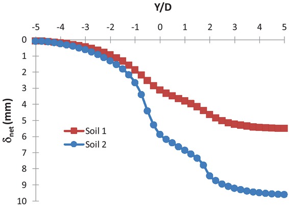
Figure 16
Distributions of net pile head settlement with tunnel advancement for two types of soils and a single pile analysis (C/D= 0.16, and E/D= 0).
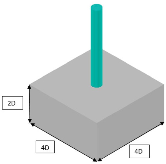
Figure 17
Virtual parallelogram represents the zone of significant influence during tunnel advancement.
Table 6
Details of centrifuge tests (prototype scale), Logagnathan et al. (2000).
| Test No. | Tunnel depth, H: m | |
|---|---|---|
| 1 | Pile length, Lp = 18 m Pile diameter, d= 0.8 m | 15 |
| 2 | EI= 1400 MN m2 Tunnel diameter, D= 6 m Stiff kaolin clay, ~75 kPa | 18 |
| 3 | 21 |
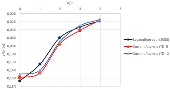
Figure 18
Comparison of the present numerical analysis with centrifuge test results.