
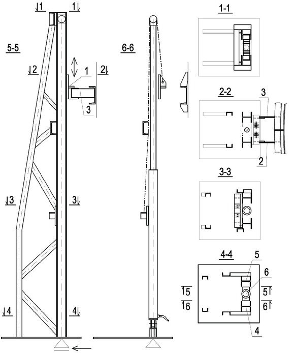
Figure 1
Layout of a tower used for tank assembly: 1, carriage (lifting chair); 2, connector A; 3, connector B; 4, chord A; 5, chord B; 6, jack
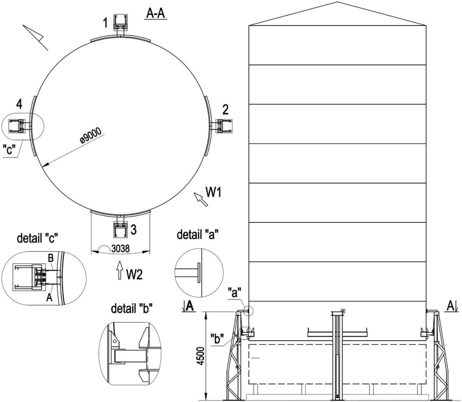
Figure 2
Scheme of the tank assembly.
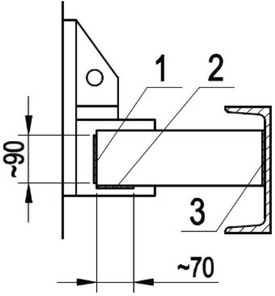
Figure 3
Details of connector welding: 1 and 2, fillet welds in the broken lap joint (1, low-quality weld; 2, proper quality weld); 3, double fillet weld
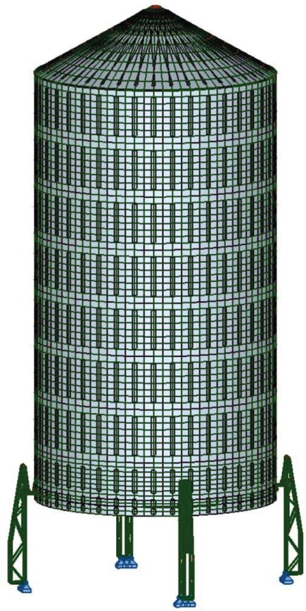
Figure 4
Model of a system tank-four towers.
Table 1
Actions of the towers (kN) based on pinned supports.
| No. of towers | Vertical action (V) | Resultant horizontal action (H) | Ratio of actions (H/V) | ||||||
|---|---|---|---|---|---|---|---|---|---|
| Chord A | Jack | Chord B | Chord A | Jack | Chord B | Chord A | Jack | Chord B | |
| 1 | 2 | 3 | 4 | 5 | 6 | 7 | 8 | 9 | 10 |
| Wind W1 – towers without cantilevers | |||||||||
| 3, 2 | –* | 60.83 | 10.40 | –* | 4.013 | 3.423 | –* | 0.066 | 0.329 |
| 4, 1 | 5.45 | 62.79 | 4.57 | 3.868 | 0.014 | 3.629 | 0.710 | 0.000 | 0.794 |
| Wind W1 – cantilevers on the chord A in every towers | |||||||||
| 1 | 5.76 | 62.57 | 4.69 | 2.554 | 0.014 | 3.359 | 0.443 | 0.000 | 0.716 |
| 2 | 11.38 | 59.84 | –* | 2.768 | 3.147 | –* | 0.243 | 0.053 | –* |
| 3 | –* | 62.15 | 9.30 | –* | 2.374 | 3.539 | –* | 0.038 | 0.380 |
| 4 | 6.08 | 62.37 | 4.36 | 2.885 | 0.000 | 3.007 | 0.475 | 0.000 | 0.690 |
| Wind W2 – towers without cantilevers | |||||||||
| 3 | 4.80 | 57.51 | 4.80 | 3.291 | 0.010 | 3.291 | 0.686 | 0.000 | 0.686 |
| 4, 2 | 2.83 | 65.46 | 7.38 | 4.846 | 0.022 | 3.152 | 1.173 | 0.000 | 0.427 |
| 1 | 4.87 | 59.83 | 4.87 | 3.551 | 0.010 | 3.551 | 0.729 | 0.000 | 0.729 |
| Wind W2 – cantilevers on the chord A in every towers | |||||||||
| 1 | 4.71 | 61.79 | 5.66 | 2.761 | 0.010 | 3.121 | 0.586 | 0.000 | 0.551 |
| 2 | 6.01 | 62.99 | 4.40 | 2.400 | 0.000 | 3.833 | 0.399 | 0.000 | 0.871 |
| 3 | 4.45 | 59.25 | 5.83 | 2.311 | 0.010 | 2.700 | 0.519 | 0.000 | 0.463 |
| 4 | 3.52 | 62.97 | 6.89 | 3.464 | 0.020 | 2.750 | 0.984 | 0.000 | 0.399 |
Table 2
Internal forces in connectors for the towers without cantilevers: wind W2.
| μ | Tower no. 3 | Tower no. 4 | Tower no. 1 | |||||||||
|---|---|---|---|---|---|---|---|---|---|---|---|---|
| Connector A and B | Connector A | Connector B | Connector A and B | |||||||||
| M | V | N | M | V | N | M | V | N | M | V | N | |
| kNm | kN | kN | kNm | kN | kN | kNm | kN | kN | kNm | kN | kN | |
| 1 | 2 | 3 | 4 | 5 | 6 | 7 | 8 | 9 | 10 | 11 | 12 | |
| In the cross section at the side of the tank | ||||||||||||
| 0 | 2.061 | -30.0 | 3.27 | 1.504 | -34.9 | 4.24 | 1.496 | -33.7 | 3.76 | 1.539 | -31.3 | 3.58 |
| 0.15 | 2.088 | -30.0 | 3.26 | 1.502 | -34.8 | 3.92 | 1.497 | -33.8 | 4.08 | 1.541 | -31.3 | 3.59 |
| 0.3 | 2.113 | -30.0 | 3.25 | 1.499 | -34.7 | 3.63 | 1.498 | -33.9 | 4.37 | 1.514 | -31.3 | 3.60 |
| ∞ | 1.981 | -30.0 | 3.29 | 1.505 | -35.1 | 5.12 | 1.486 | -33.5 | 2.89 | 1.641 | -31.3 | 3.56 |
| In the cross section at the side of the carriage | ||||||||||||
| 0 | -6.526 | -30.0 | 3.27 | -8.478 | -34.9 | 4.24 | -8.149 | -33.7 | 3.76 | -7.376 | -31.3 | 3.58 |
| 0.15 | -6.499 | -30.0 | 3.26 | -8.457 | -34.8 | 3.92 | -8.171 | -33.8 | 4.08 | -7.405 | -31.3 | 3.59 |
| 0.3 | -6.474 | -30.0 | 3.25 | -8.439 | -34.7 | 3.63 | -8.191 | -33.9 | 4.37 | -7.432 | -31.3 | 3.60 |
| ∞ | -6.608 | -30.0 | 3.29 | -8.540 | -35.1 | 5.12 | -8.095 | -33.5 | 2.89 | -7.301 | -31.3 | 3.56 |
Table 3
Radial displacements of the shell in a connection point for the wind W2.
| μ | Towers without cantilevers | Towers with cantilevers | ||||||
|---|---|---|---|---|---|---|---|---|
| No. 3 | No. 4 | No. 1 | No. 2 | No. 3 | No. 4 | No. 1 | No. 2 | |
| – | cm | cm | cm | cm | cm | cm | Cm | cm |
| 0 | 4.40 | 2.64 | 2.96 | 2.64 | 2.85 | 2.18 | 2.29 | 2.19 |
| 0.15 | 4.48 | 2.64 | 2.89 | 2.64 | 2.86 | 2.18 | 2.28 | 2.20 |
| 0.3 | 4.54 | 2.64 | 2.82 | 2.64 | 2.87 | 2.18 | 2.27 | 2.20 |
| ∞ | 4.20 | 2.64 | 3.16 | 2.64 | 2.81 | 2.18 | 2.33 | 2.20 |
Table 4
Resultant normal stress in the shell in the connection points for the wind W2.
| μ | Towers without cantilevers | Towers with cantilevers | ||||||
|---|---|---|---|---|---|---|---|---|
| No. 3 | No. 4 | No. 1 | No. 2 | No. 3 | No. 4 | No. 1 | No. 2 | |
| - | MPa | MPa | MPa | MPa | MPa | MPa | MPa | MPa |
| 0 | 209.9/178.7 | 202.3/179.2 | 191.1/168.7 | 202.4/179.2 | 141.3/169.0 | 149.8/151.5 | 144.9/149.5 | 147.8/153.0 |
| 0.15 | 211.0/179.6 | 205.5/179.3 | 190.0/167.8 | 205.6/179.2 | 142.3/169.4 | 151.7/151.4 | 145.5/149.5 | 147.2/152.9 |
| 0.3 | 212.1/180.3 | 208.5/179.3 | 188.9/167.0 | 208.5/179.3 | 143.5/169.8 | 153.6/151.4 | 146.3/149.5 | 146.9/152.9 |
| ∞ | 206.6/176.3 | 207.9/178.9 | 194.2/170.9 | 207.9/178.9 | 143.5/165.9 | 146.3/151.5 | 146.7/149.3 | 155.1/152.7 |
[i] *The first of the values in cells refers to the stress in the area of the connections at the ends of the channel and the second value pertains to the stress in the area of the connection at half of the length of this channel (see figure 2).