
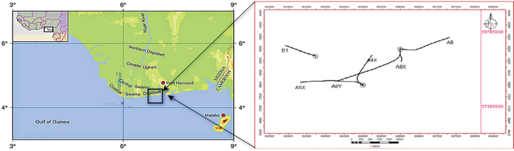
Figure 1:
This map depicts a generic location map of the research region as well as the basic concession map.
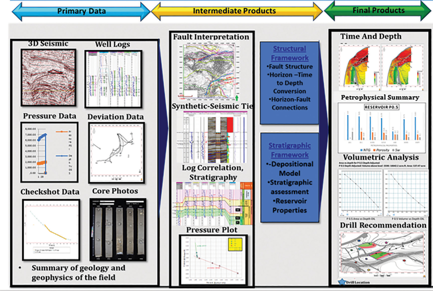
Figure 2:
Flowchart for the methodology utilized in the current study.
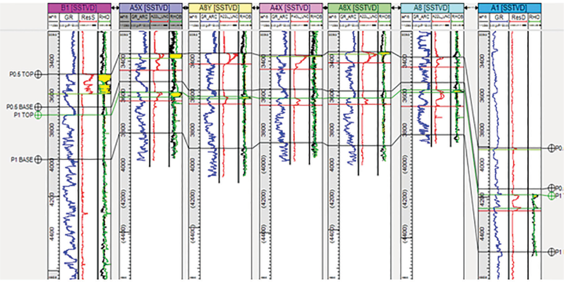
Figure 3:
Well log correlations between the wells analyzed.
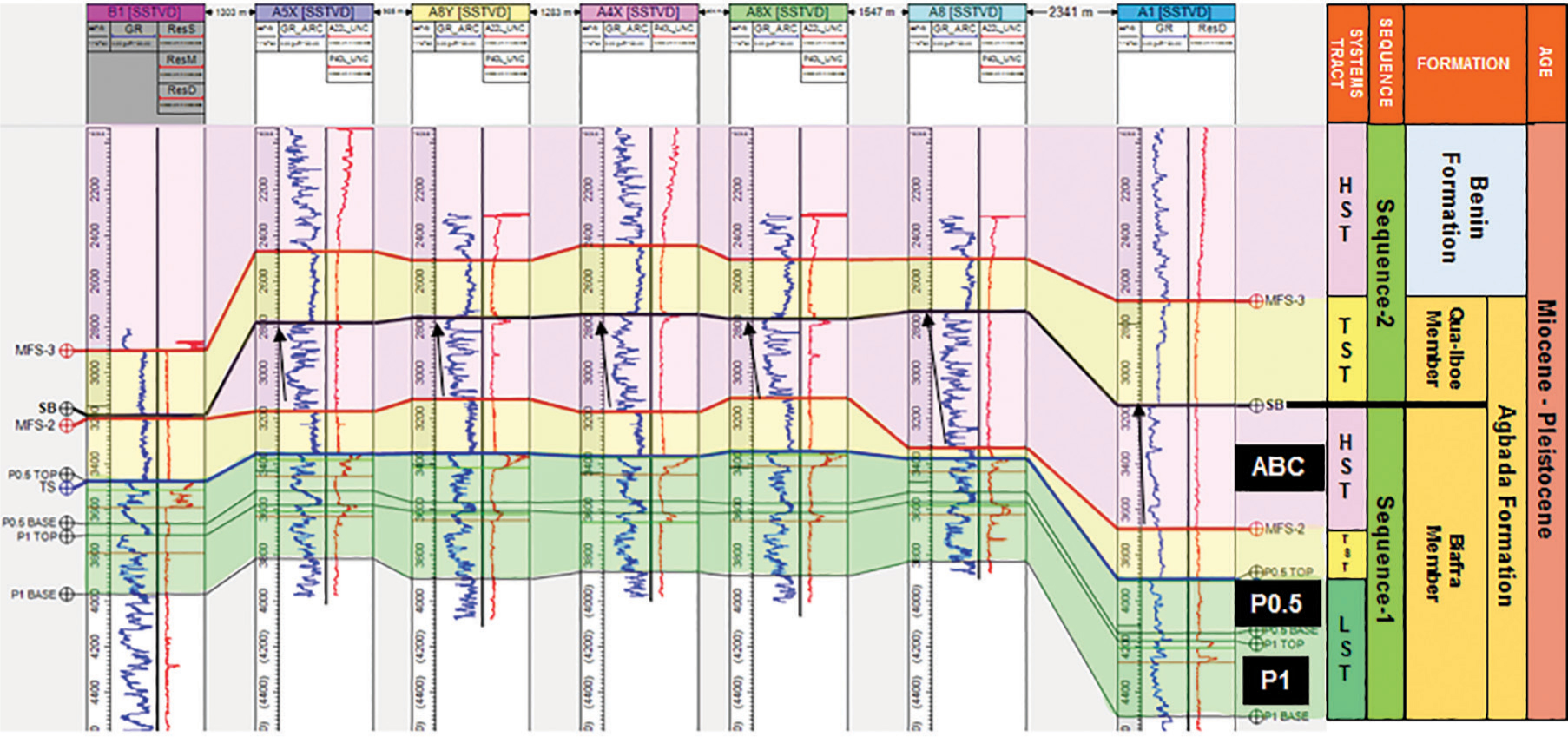
Figure 4:
Well log correlations between the studied wells with stratigraphic correlation.
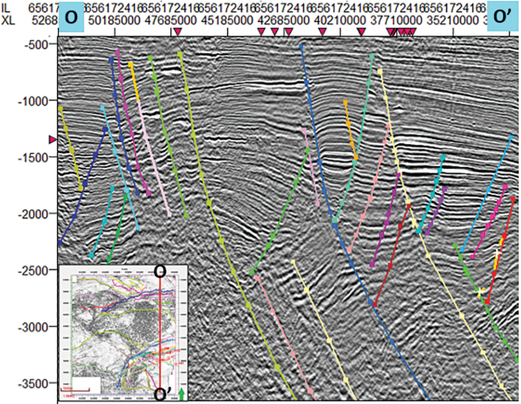
Figure 5:
Fault framework as delineated in the seismic sections.
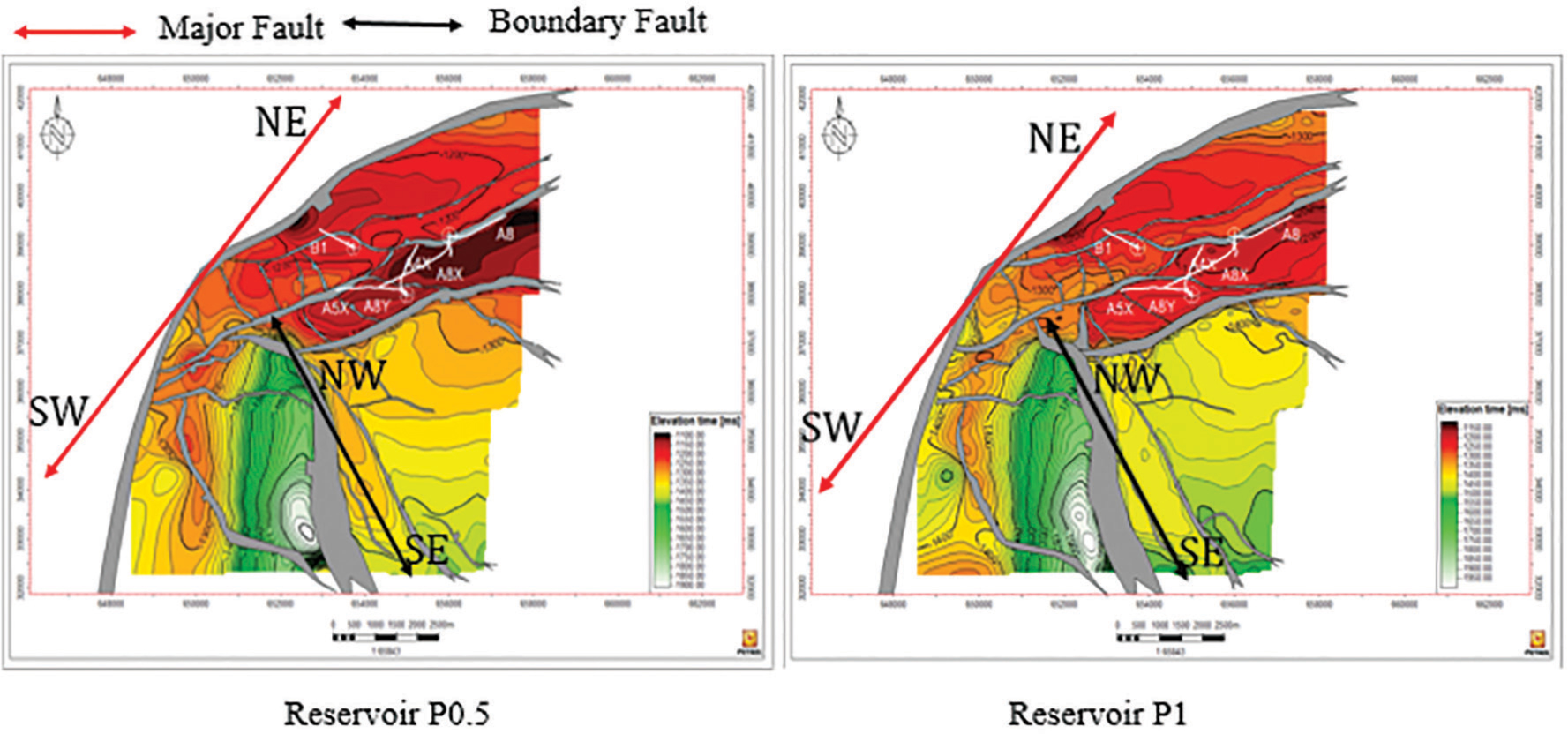
Figure 6:
Horizon and fault mapping for Reservoir P 0.5 and P 1.
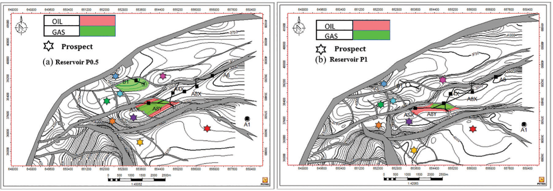
Figure 7:
Depth map for reservoir P 0.5 and P 1 showing GOC from both reservoirs.
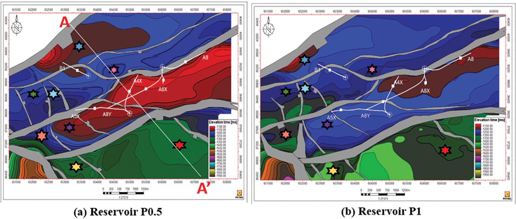
Figure 8:
Time attribute map for reservoir P 0.5 and P 1.
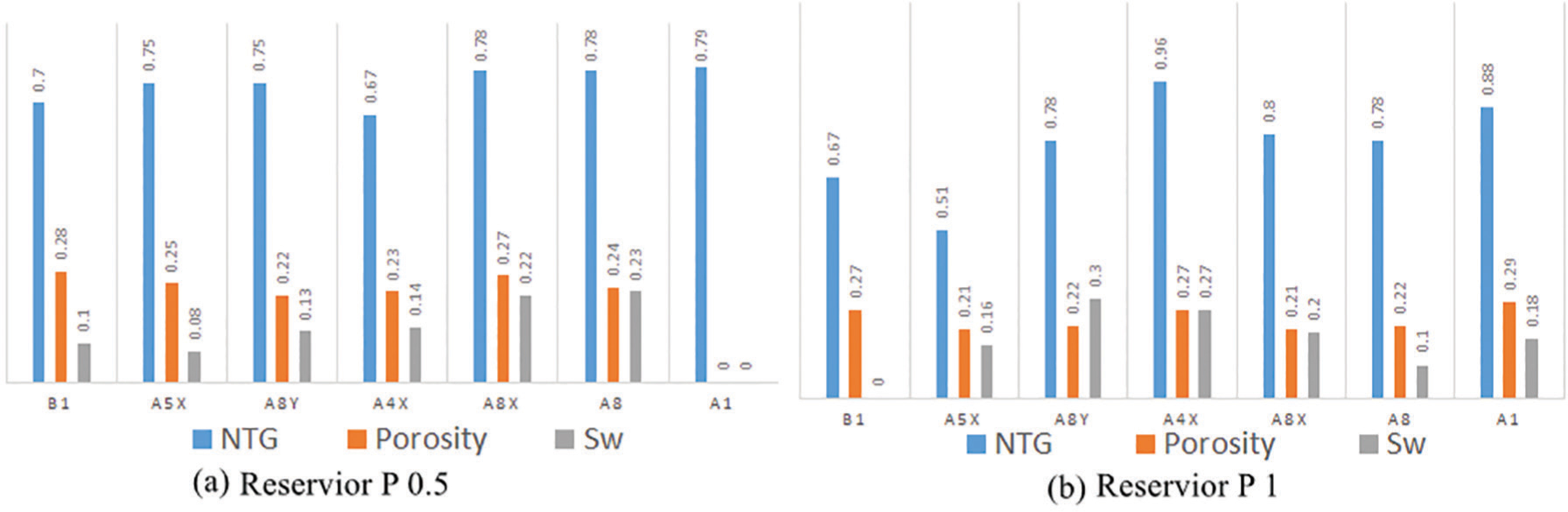
Figure 9:
Summary of the result of the petrophysical analysis from the studied wells for both Reservoir (a) P 0.5 and (b) P 1.
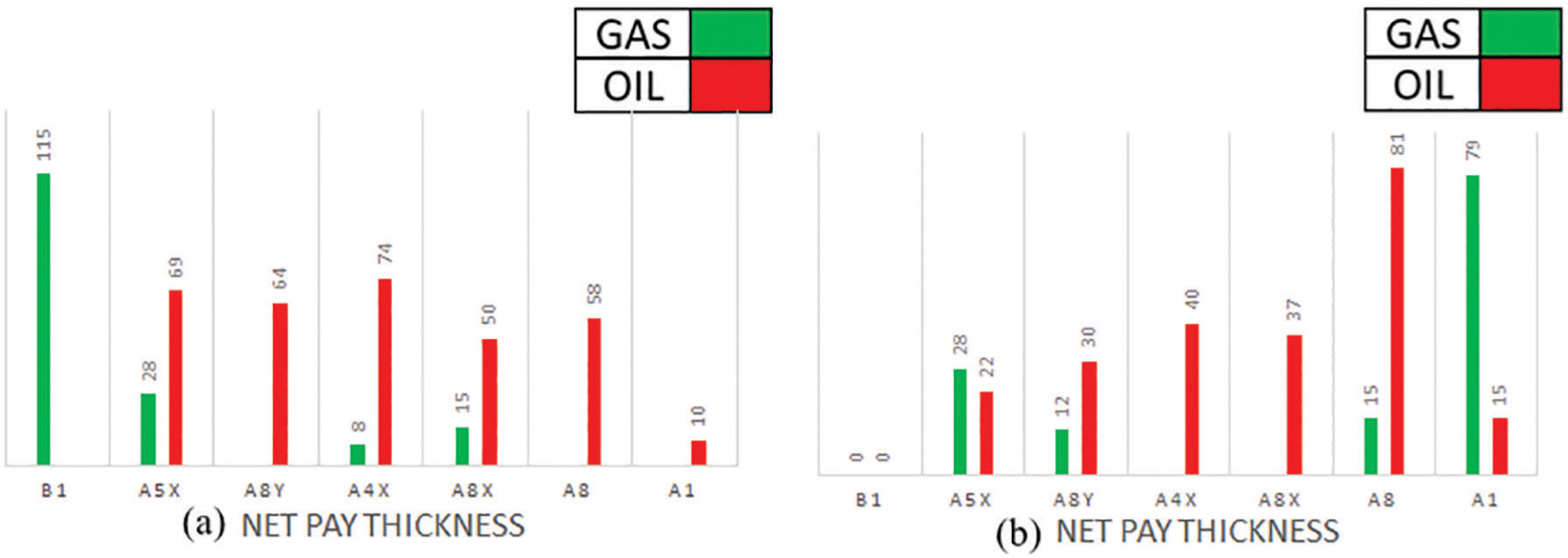
Figure 10:
Summary of the result of the net pay thickness for oil and gas in reservoirs P 0.5 and P 1.
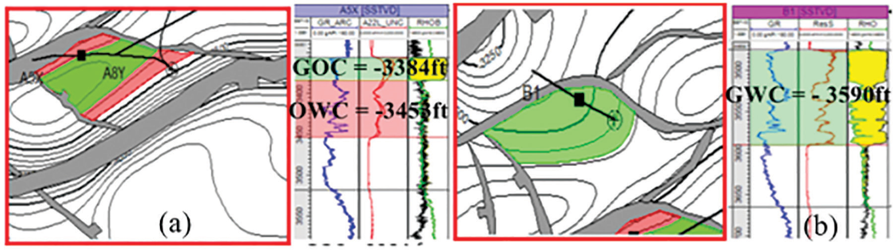
Figure 11:
Oil-gas-water contact in reservoirs P 0.5 and P 1.
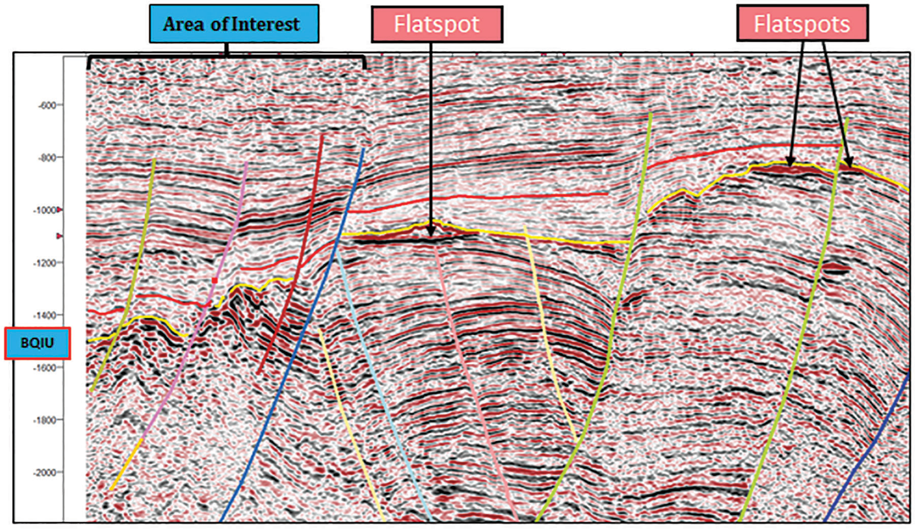
Figure 12:
Viable prospects in the H-field for exploration.
Table 1:
Estimates of mean; porosity, NTG, water saturation, and hydrocarbon volume in the two examined H-Field reservoir intervals.
| Reservoir Interval | Average Porosity (%) | Average NTG (%) | Average Water Saturation (%) | Average Pay Thickness (Gas) | Average Pay Thickness (Oil) | GIIP (BSCF) | STOIIP (MMSTB) |
|---|---|---|---|---|---|---|---|
| P 0.5 | 24.3 | 74.5 | 64 | 41.75 | 54.16 | 23.83 | 11.5 |
| P 1 | 24.1 | 76 | 73 | 33.5 | 37.5 | 0.64 | 1.13 |