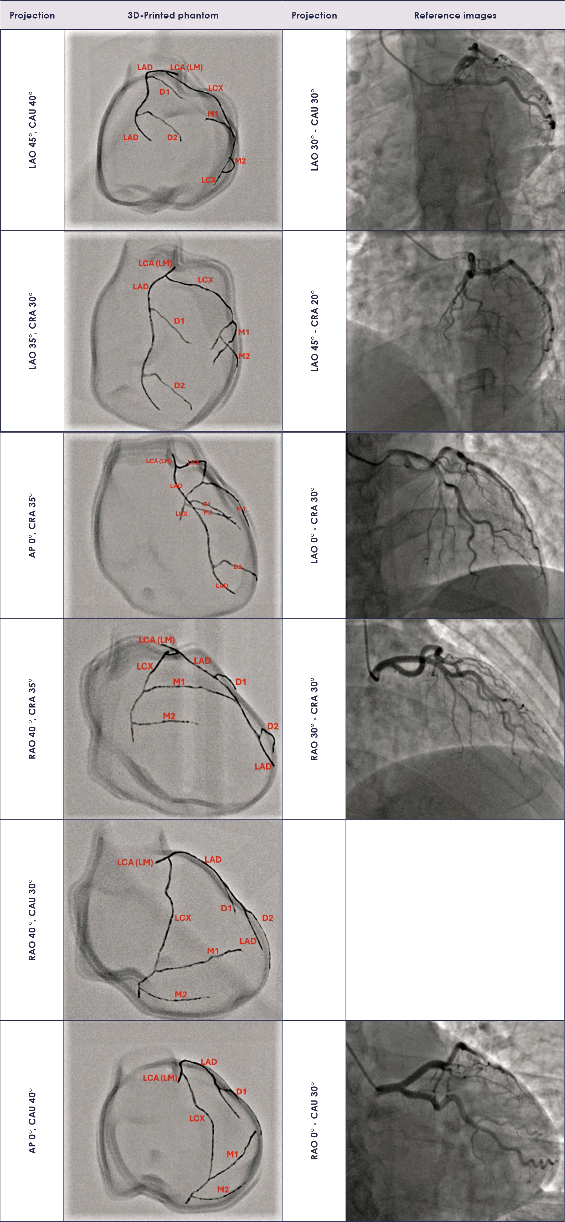
TABLE 1.
Projections used in fluoroscopic imaging of the heart phantom with coronary arteries and projections from the literature used for comparison with our images19
| Projections used in phantom imaging | Projections from the literature | |
|---|---|---|
| Left coronary Artery | LAO 45° – CAU 40° | LAO 30° – CAU 30° |
| LAO 35° – CRA 30° | LAO 45° – CRA 20° | |
| AP 0° – CRA 35° | LAO 0° – CRA 30° | |
| RAO 40° – CRA 35° | RAO 30° – CRA 30° | |
| RAO 40° – CAU 30° | ||
| AP 0° – CAU 40° | RAO 0° – CAU 30° | |
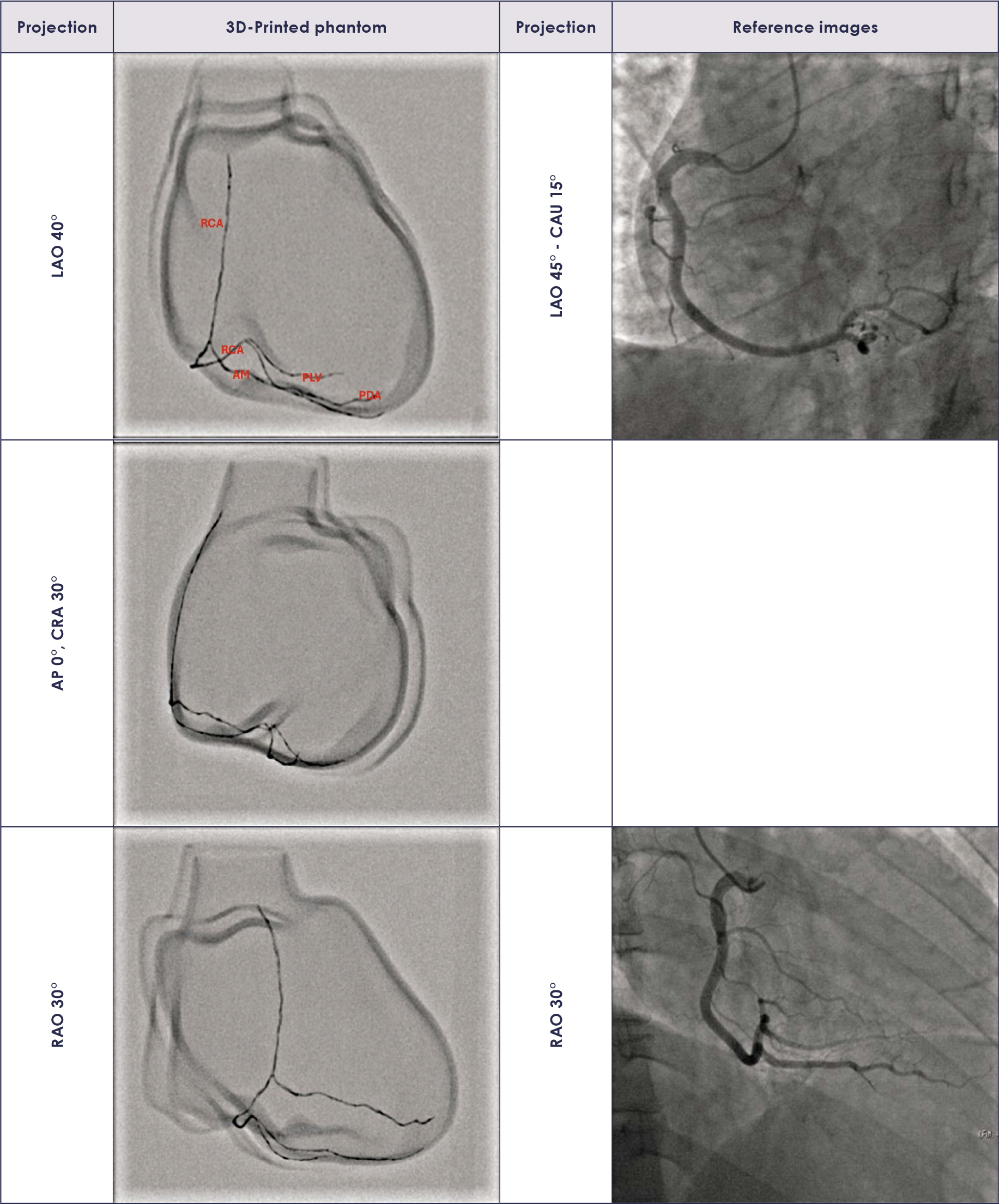
| Right coronary Artery | LAO 40° | LAO 45° – CAU 15° |
| AP 0° – CRA 30° | ||
| RAO 30° | LAO 45° – CAU 15° |
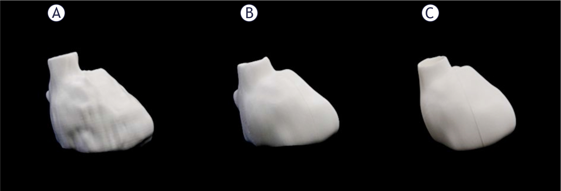
Figure 1.
3D-printed model with honeycomb shaped infill (A) hollow model with honeycomb shaped infill of the walls (B), and hollow model with 100% infill of the walls (C).
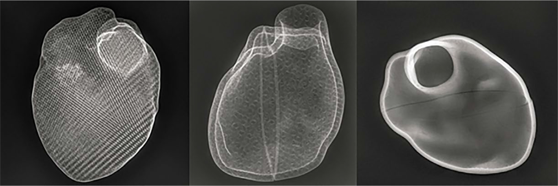
FIGURE 2.
Radiographs of 3 different heat phantoms: full model with honeycomb shaped infill (A), hollow model with honeycomb shaped infill of the walls (B), and hollow model with 100% infill of the walls (C).
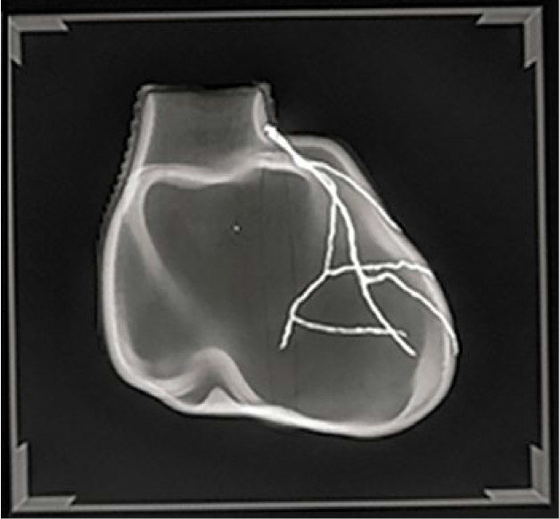
FIGURE 3.
Radiograph of the heart model with vessels drawn by a mixture of UV gel and metallic powder.
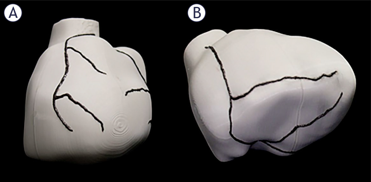
Figure 4.
3D-printed heart model with the left (A), and the right (B) coronary artery.
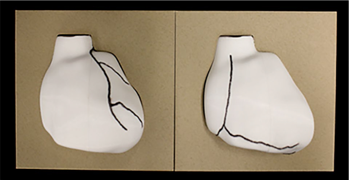
Figure 5.
3D-printed models in their custom bases.
TABLE 2.
Comparison of the obtained right coronary artery images of the heart model with images from the literature
 |