
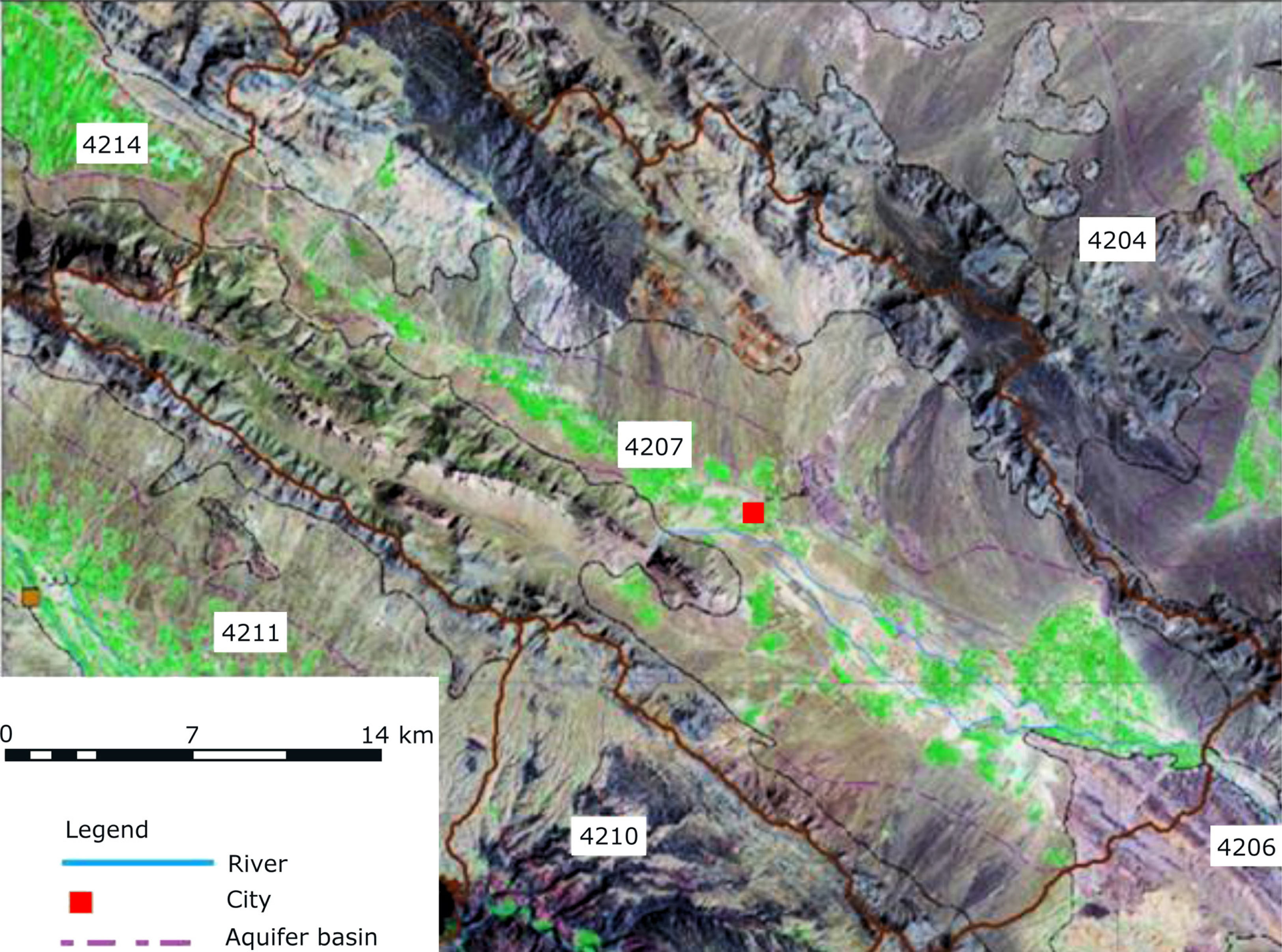
Fig. 1
Geographical states of the subject area.
Table 1
The description of wells, springs and subterranean.
| Consumption type | Numbers | Discharge (Mm3) | Percentage |
|---|---|---|---|
| Wells | 401 | 31.2 | 49.1 |
| Springs | 34 | 21.6 | 34.0 |
| Subterranean | 61 | 10.7 | 16.9 |
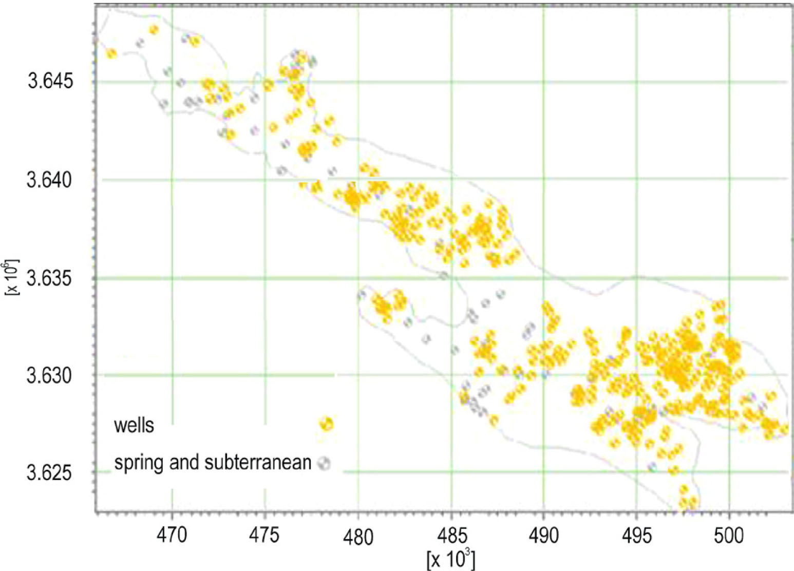
Fig. 2
The geographical distribution of studied wells, spring and subterranean. The x-axis represents the aquifer length (p km−1) and the y-axis represents the aquifer width (p km−1).
Table 2
The hydrogeology balance in the subject area.
| Type | Precipitation | Evaporation | Rainfall runoff | Infiltration of precipitation |
|---|---|---|---|---|
| Volumes [Mm3] | 214.8 | 133.0 | 40.9 | 40.9 |
Table 3
The Groundwater balance in the subject area.
| Type | Infiltration of surface floodwaters | Groundwater | Water consumed in agricultural, drinking, industry | Infiltration of precipitation |
|---|---|---|---|---|
| Input [Mm3] | 12.4 | 11.5 | 15.0 | 5.6 |
| Outflow[Mm3] | 0.0 | 9.3 | 41.3 | 0.0 |
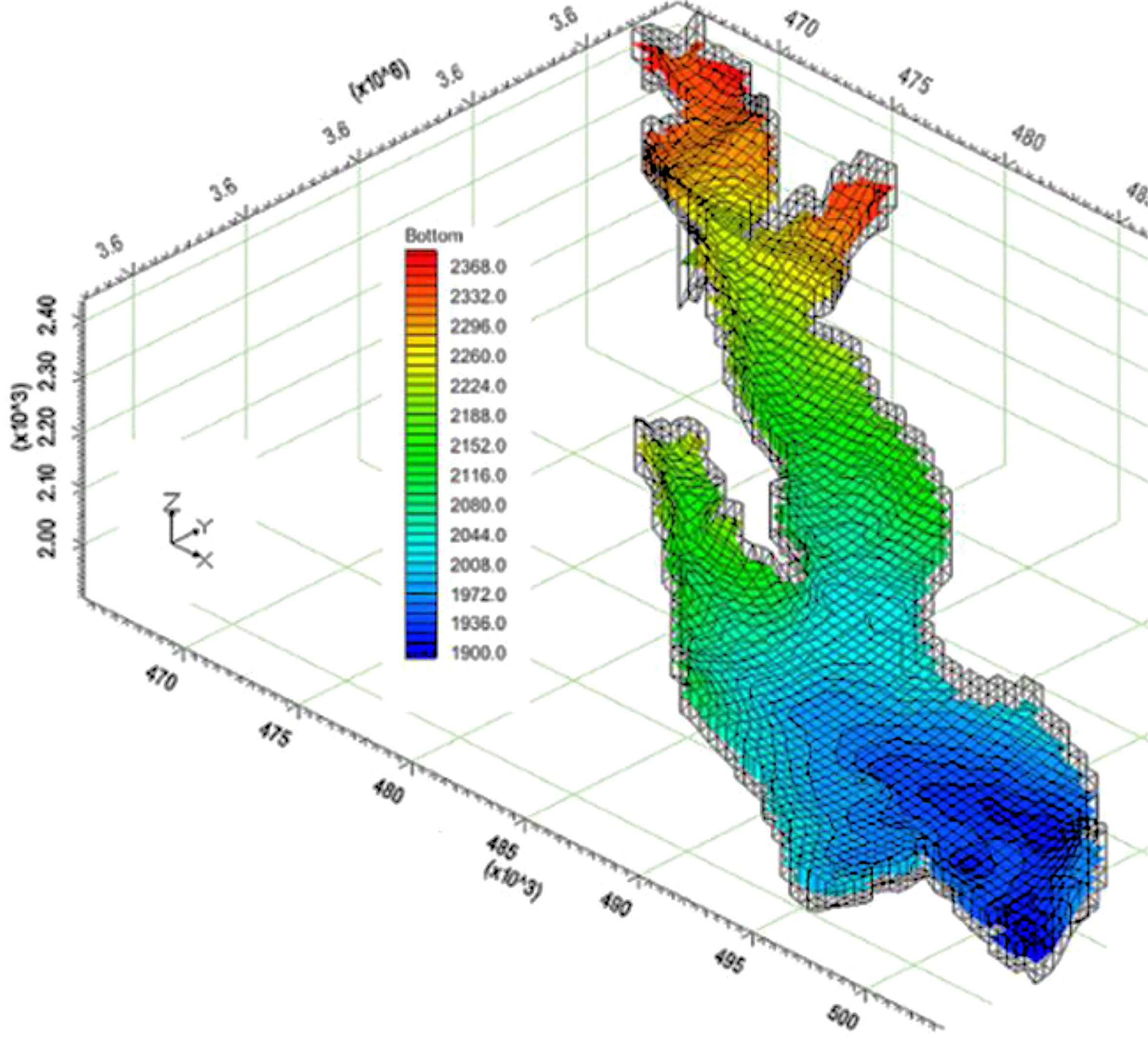
Fig. 3
The number of layers with boundary conditions.
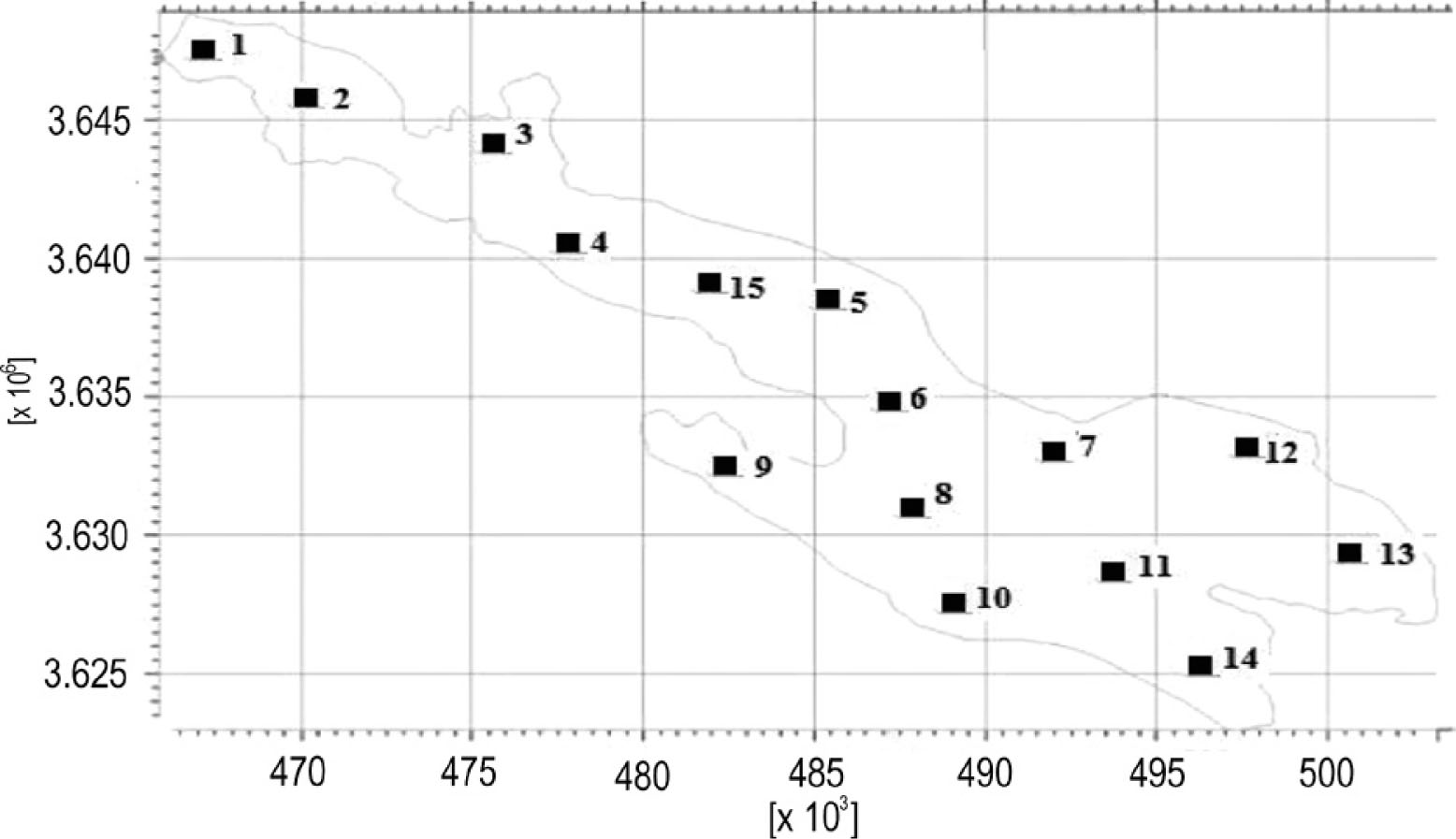
Fig. 4
The key numbers assigned to the pilots to determine surface recharge parameters.
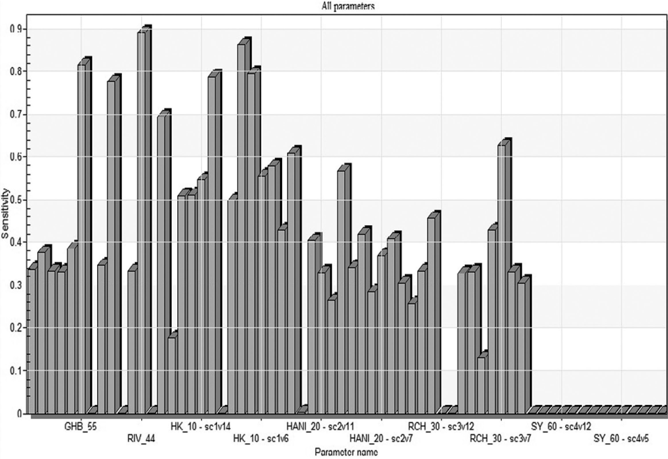
Fig. 5
Comparative sensitivity analysis of all parameters in the unsteady calibration. The x-axis represents the parameters name as follows: the transferability coefficient at the inlet and outlet boundaries of the aquifer with GHB. The transferability of the river waterways network with RIV. Horizontal hydraulic conductivity with HK. Surface recharge of aquifer with RCH. Horizontal anisotropy of hydraulic conductivity with HANI. Specific yield with SY. The y-axis represents the sensitivity analysis of aquifer for these parameters.
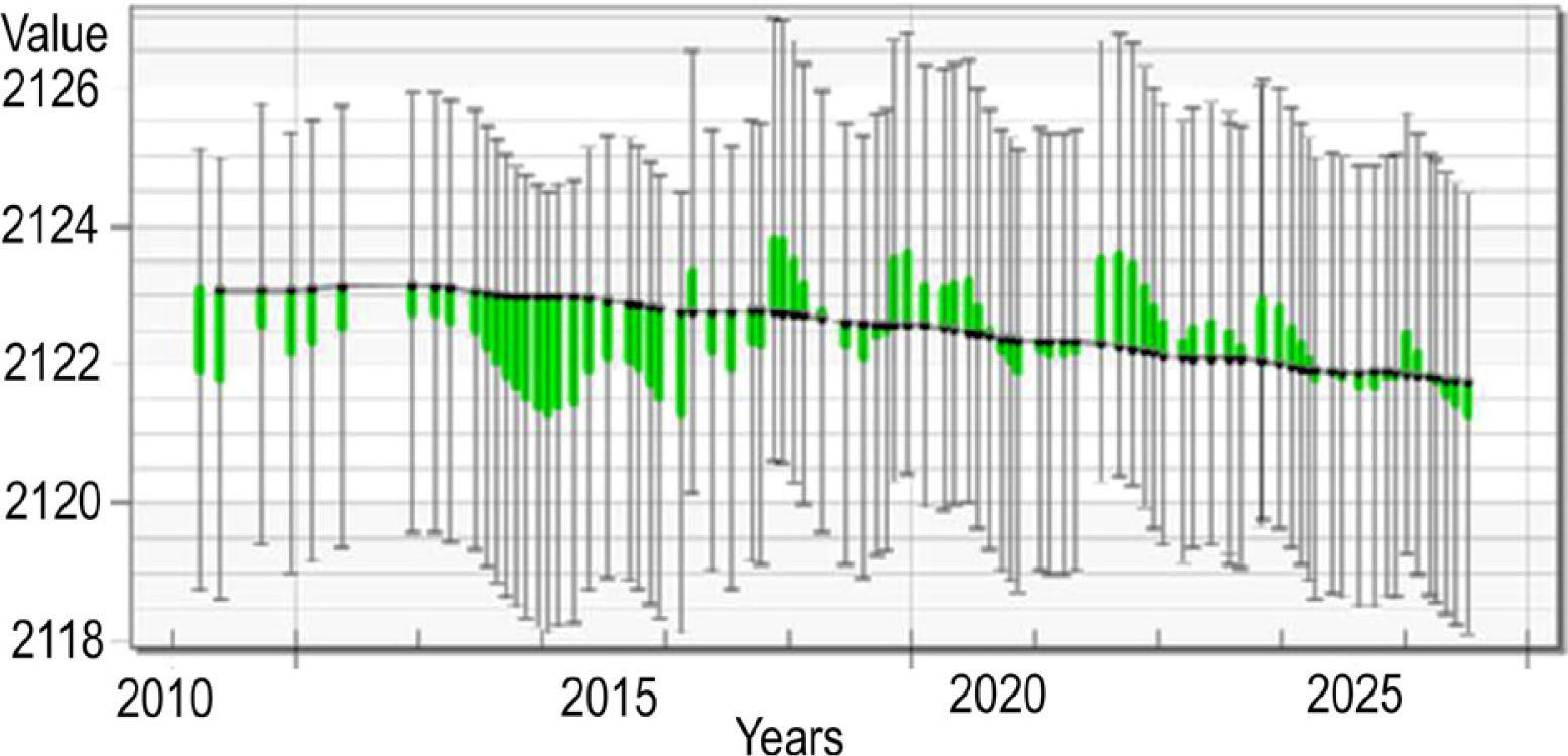
Fig. 6
A – the location of observation and exploration wells. B – the error rate for the values of the computational data in the verification phase – Observation well #2; the x-axis represents time (p a−1) and the y-axis represents groundwater level in different wells (p m−1).