
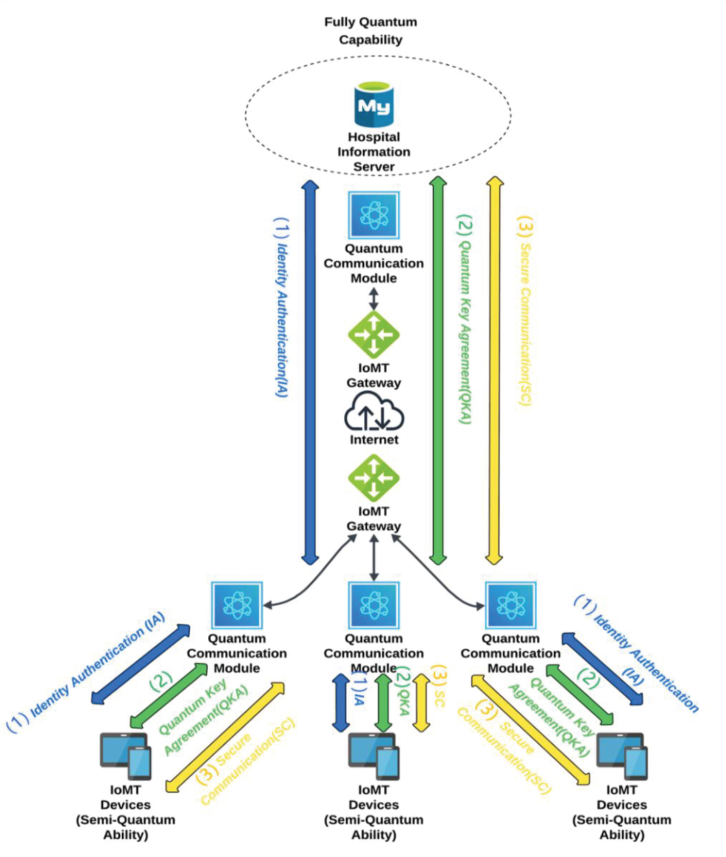
Figure 1.
Healthcare model with CASQKA.
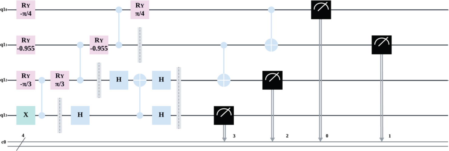
Figure 2.
Quantum circuit diagram for preparing and measuring a 4-Particle W States.
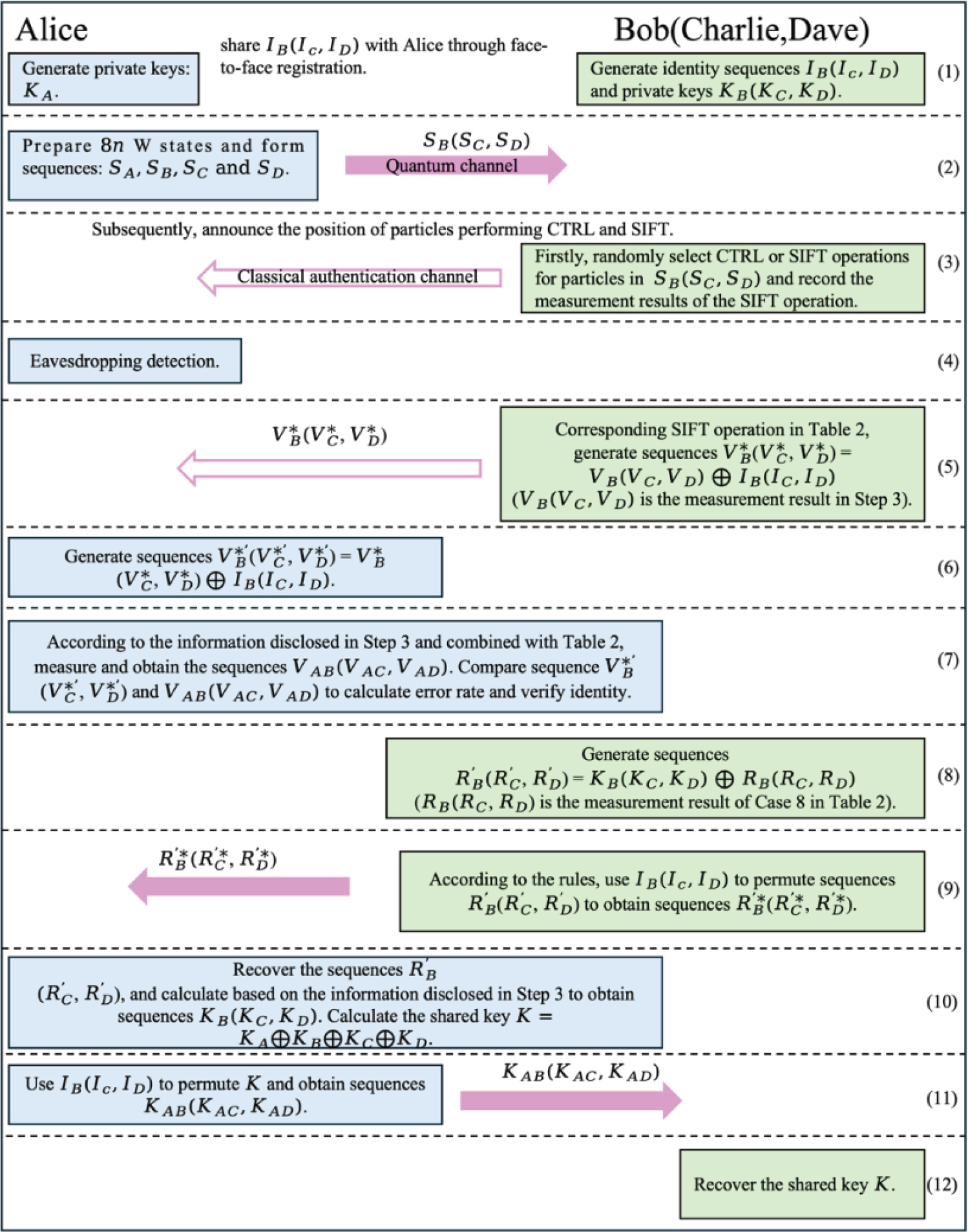
Figure 3.
Workflow of the proposed protocol.
Table 2.
All operational scenarios of Bob, Charlie, and Dave.
| Case | Bob | Charlie | Dave | Protocol phase |
|---|---|---|---|---|
| 1 | CTRL | CTRL | CTRL | |
| 2 | CTRL | CTRL | SIFT | |
| 3 | CTRL | SIFT | CTRL | |
| 4 | CTRL | SIFT | SIFT | Security check |
| 5 | SIFT | CTRL | CTRL | |
| 6 | SIFT | CTRL | SIFT | |
| 7 | SIFT | SIFT | CTRL | |
| 8 | SIFT | SIFT | SIFT | Key agreement |
Table 3.
Variable-Meaning.
| IB, IC, ID | Bob/Charlie/Dave’s pre-shared identity bit strings (n bits) |
| KA, KB, KC, KD | Each party’s private key string (n bits) |
| SA, SB, SC, SD | The four-particle sequences of the W state are held by Alice, Bob, Charlie, and Dave, respectively. |
| VB, VC, VD | The n-bit outcomes of Z-basis measurements performed by Bob/Charlie/Dave at the SIFT positions. |
| The XOR of the measurement outcome with the identity string, used for authentication. | |
| VAB, AC, VAD | The classical bit string actually measured by Alice at the corresponding positions, used for comparison and verification. |
| The n-bit SIFT measurement results of Bob/Charlie/Dave in Case-8 used to conceal the private key the final 4-party shared key | |
| KAB, KAC, KAD | The key segments permuted by Alice using IB, IC, ID are sent to Bob/Charlie/Dave, respectively. |
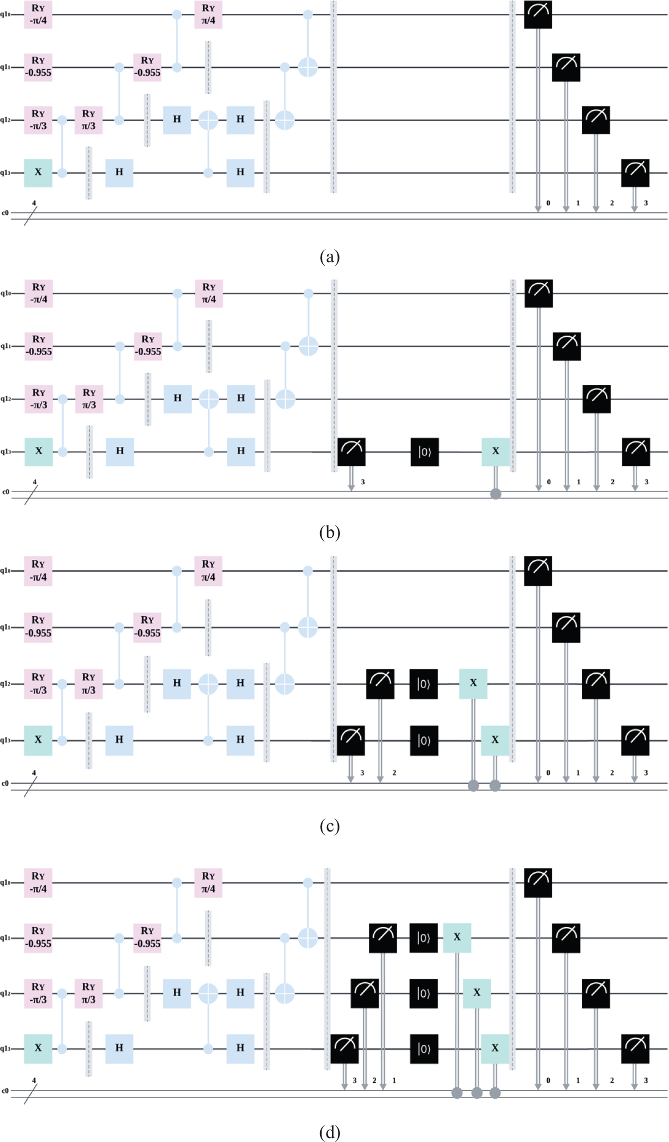
Figure 4.
(a) Quantum circuit for case 1 in Table 2. (b) Quantum circuit for case 2 in Table 2 (similar to case 3 and case 5 in Table 2). (c) Quantum circuit for case 4 in Table 2 (similar to case 6 and case 7 in Table 2). (d) Quantum circuit for case 8 in Table 2.
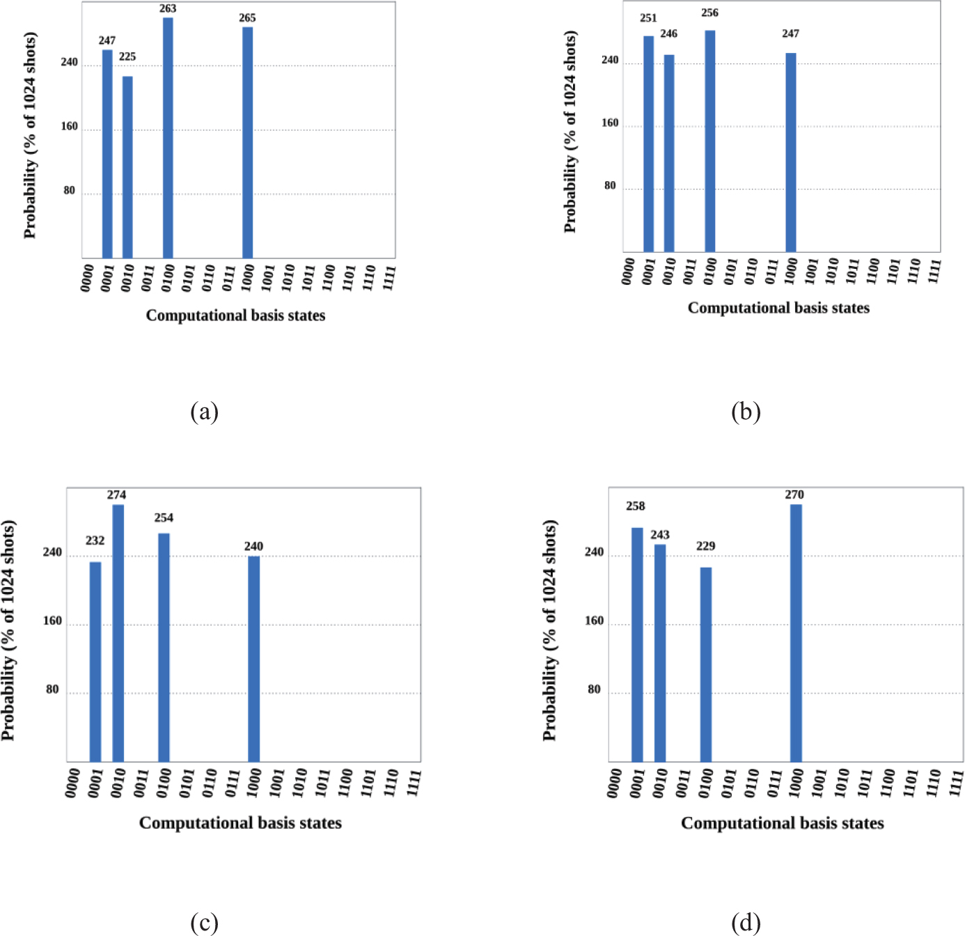
Figure 5.
(a) Run results of (a) in Figure 4. (b) Run results of (b) in Figure 4. (c) Run results of (c) in Figure 4. (d) Run results of (d) in Figure 4.
Table 4.
Simulation-Experiment Parameter.
| Platform | IBM Quantum |
|---|---|
| Software Development Kit | Qiskit(2.1.1) |
| Noise parameters (amplitude damping noise, depolarizing noise) | (0.001,0.01) (0.005,0.02) (0.01,0.03) (0.02,0.04) |
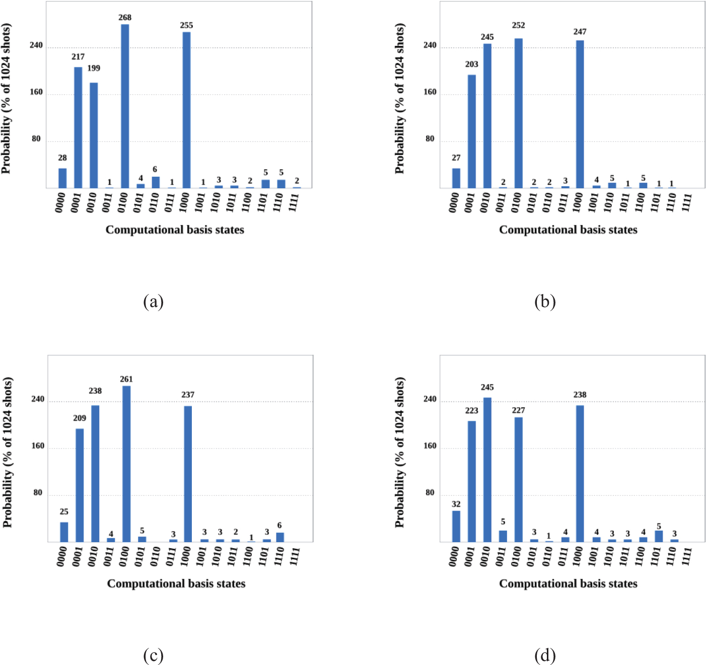
Figure 6.
Measurement results of the quantum circuit in Figure 4 under noisy environment.
Table 5.
Comparison of the proposed CASQKA protocol with other protocols.
| Protocol | Quantum resource | Identity authentication function | Semi-quantum properties | Qubit efficiency (%) |
|---|---|---|---|---|
| Ref. [36] | Cluster states | No | Yes | 2.08 |
| Ref. [28] | Cluster states | No | Yes | 1.60 |
| Ref. [39] | Five qubit entangled states | Yes | No | 7.70 |
| Ref. [40] | Bell states | No | Yes | 6.70 |
| Ref. [25] | Bell states | Yes | No | 16.67 |
| Ref. [22] | Four-particle GHZ states | Yes | No | 53.33 |
| Ref. [49] | Single-particle states | Yes | No | 16.67 |
| Ref. [50] | three-particle GHZ-like states | No | Yes | 16.67 |
| Proposed protocol | W states | Yes | Yes | 2.43 |
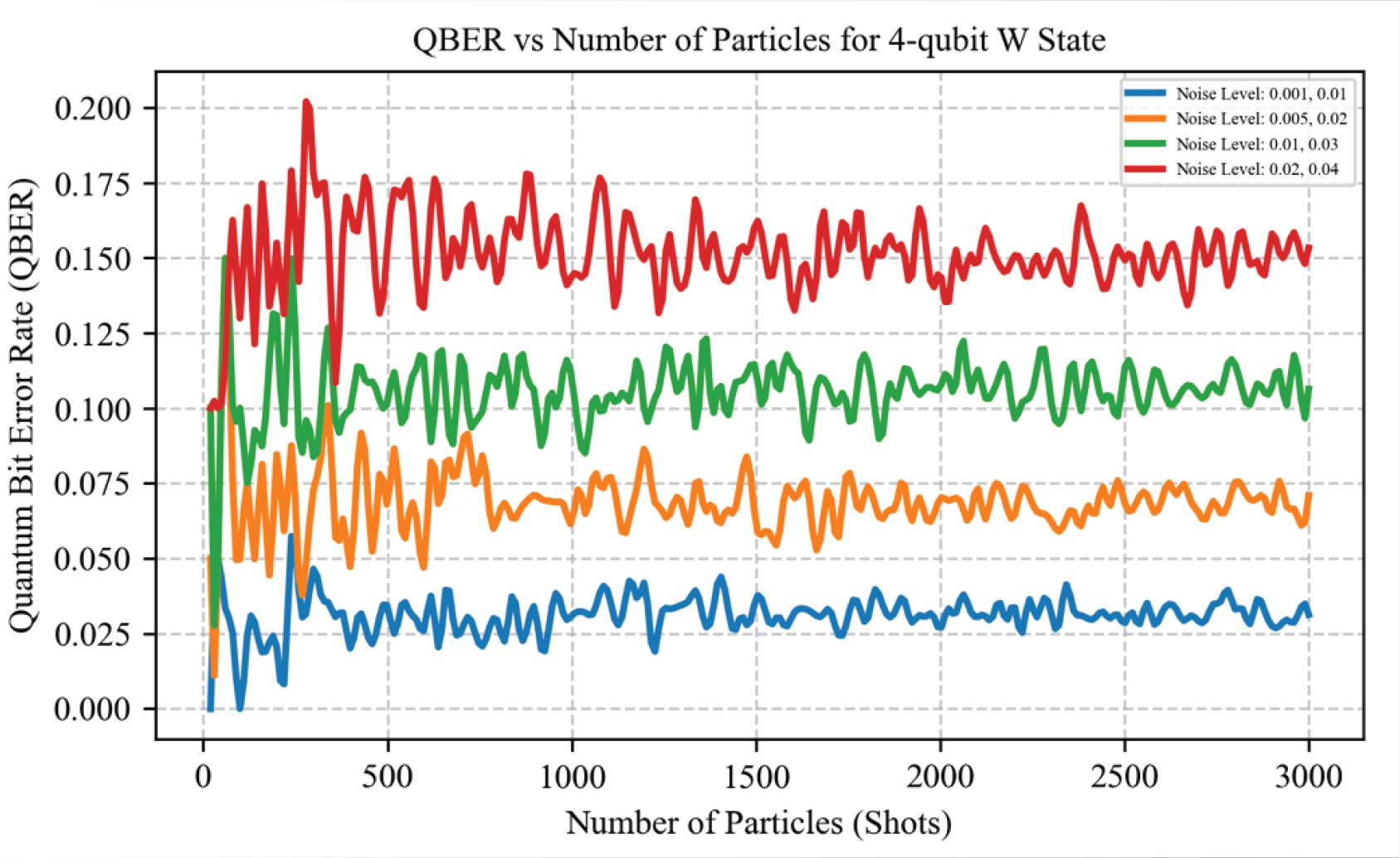
Figure 7.
Quantum bit error rate under various noise levels.
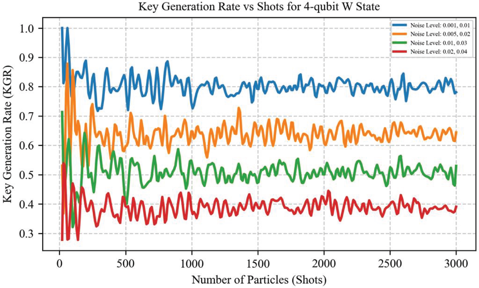
Figure 8.
Key generation rate under various noise levels.
Table 6.
Communication complexity comparison.
| Metric | Proposed protocol | Ref [5] |
|---|---|---|
| Quantum communication complexity | 30n qubits | n qubits |
| Classical communication complexity | 3n classical bits | ~0.5n classical bits |
| Total communication complexity | 33n bits | 1.5n bits |
| Qubit efficiency (η) | 3.03% | ~66.67% |