
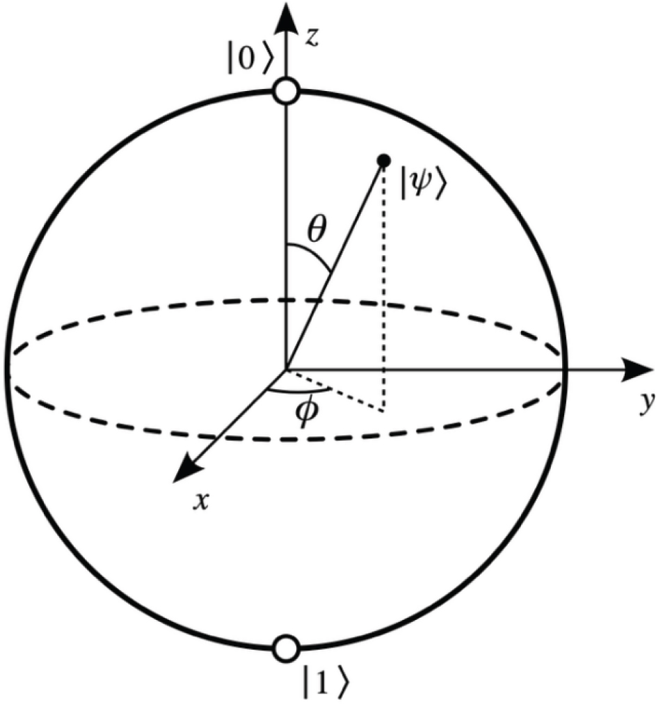
Figure 1.
Representation of |ψ〉 as a vector on the Bloch sphere.
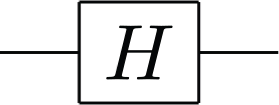
Figure 2.
Pictorial representation of Hadamard gate in a circuit.

Figure 3.
Pictorial representation of the action of Φ gate on a qubit (or a quantum state). Here, in accordance with Equations (7) and (8), x = 0 or 1.
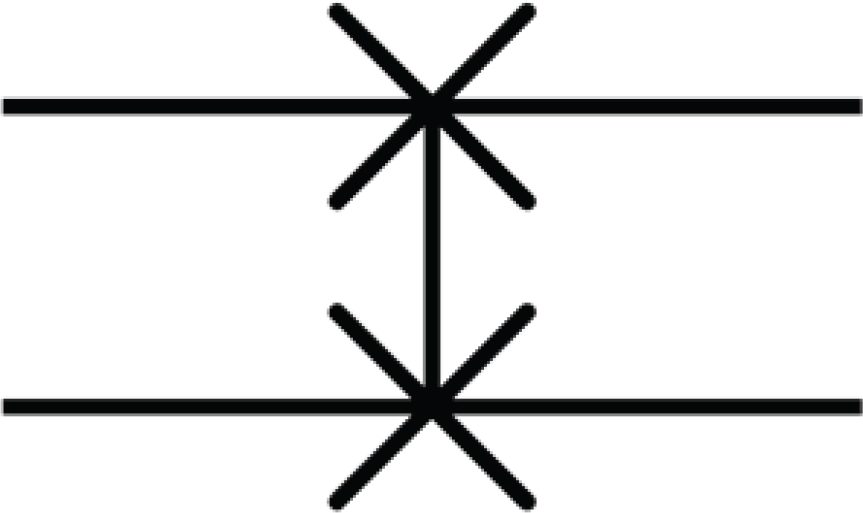
Figure 4.
Pictorial representation of SWAP gate in a circuit.
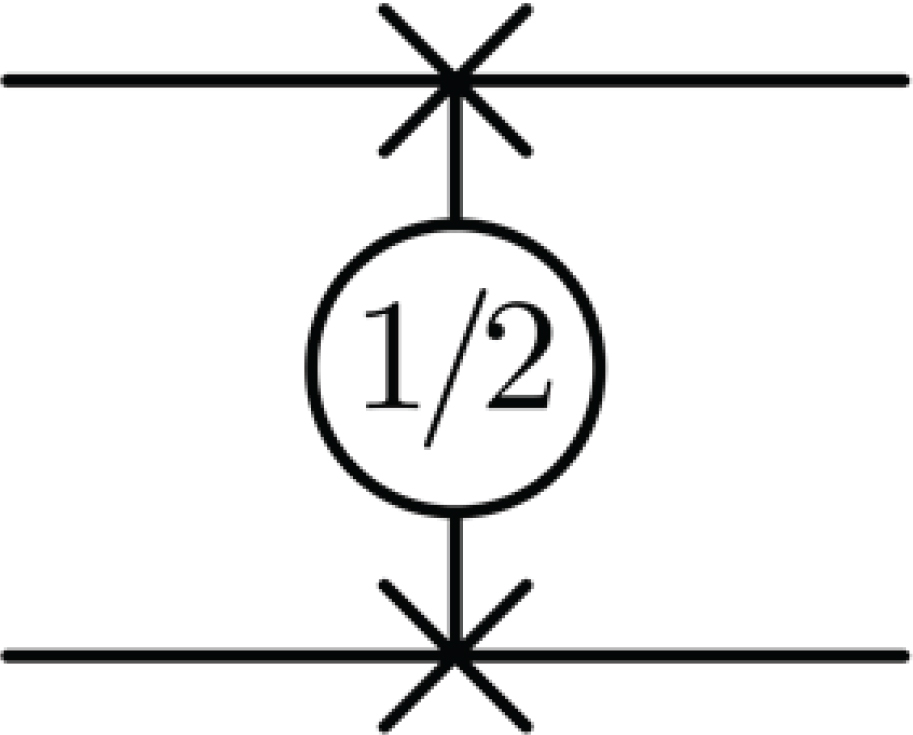
Figure 5.
Pictorial representation of gate in a circuit.
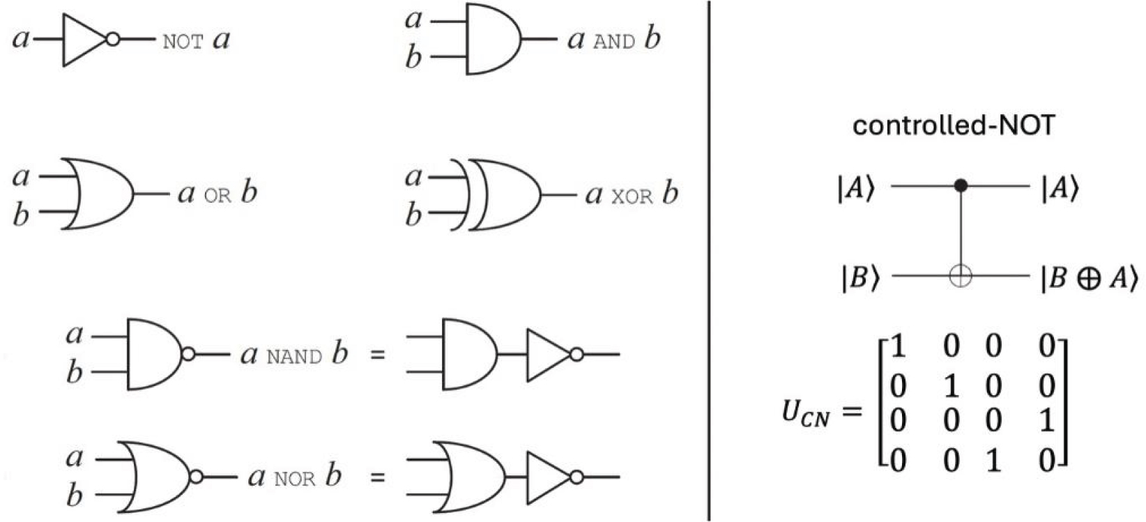
Figure 6.
Some standard single and multiple bit gates (left), and the controlled-NOT (CNOT) gate along with its matrix representation (right). Adapted in part from ref. [1].
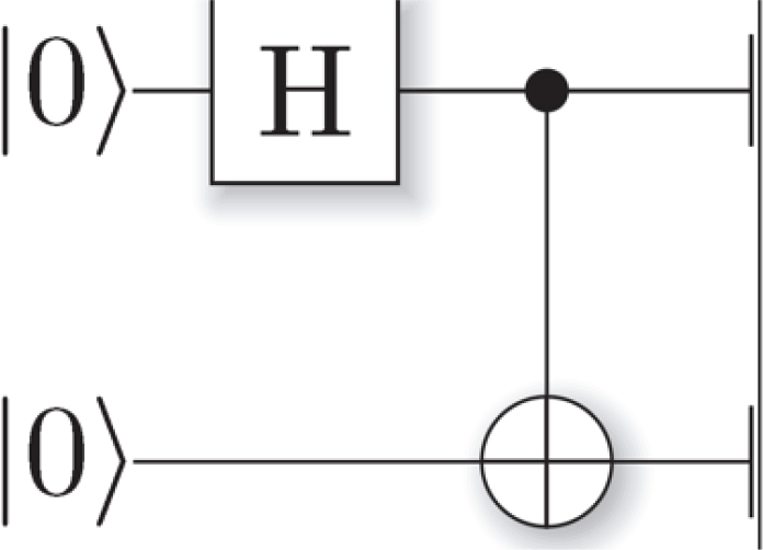
Figure 7.
H–CNOT combinational quantum circuit to produce |Φ+〉 when the input is |00〉.
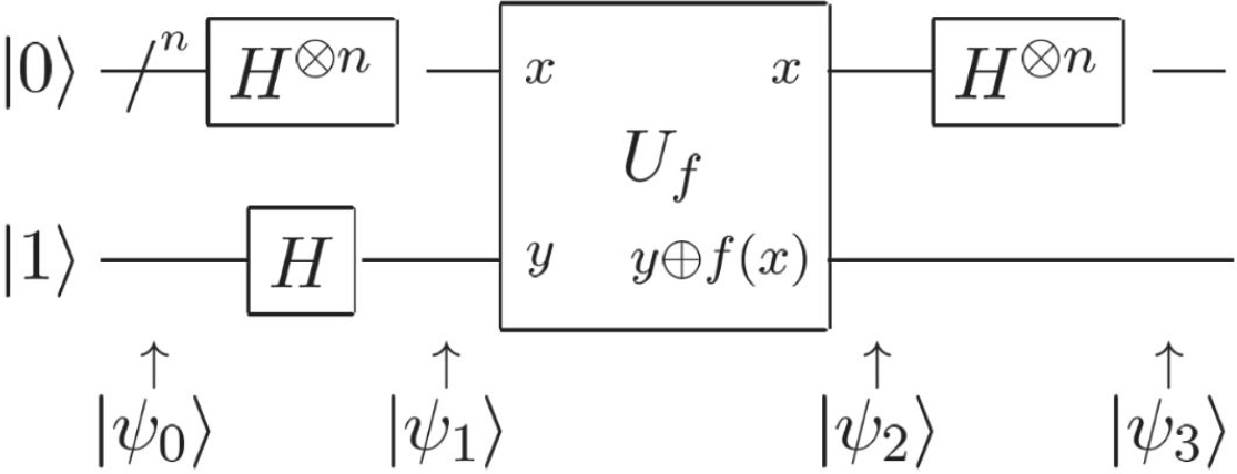
Figure 8.
Representation of Deutsch–Jozsa algorithm as a quantum circuit, where ‘/n’ represents a set of n qubits. Adapted in part from ref. [1].
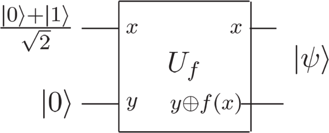
Figure 9.
A sample circuit representing quantum parallelism, where states on the left represent the input and |ψ〉 is given by Equation (16).1