
1. Introduction
The transverse flux machine (TFM) has undergone a significant evolution since its conceptual origins in an 1888 patent (Mordey, 1890). Although it remained largely dormant for nearly a century, the principle was refined in the late 20th century by leveraging modern technological advancements (Weh, 2000; Weh and May, 1986). This sparked a surge in scholarly interest over the last three decades, as researchers sought to capitalise on the TFM’s exceptional power-to-weight and power-to-size ratios, which offer clear advantages over conventional machine topologies (Guo et al., 2006; Husain et al., 2017; Zhang et al., 2016). Despite these performance benefits, TFMs have faced limited industrial adoption and manufacturing hurdles. These challenges are primarily rooted in their structural complexity, which increases production costs and impacts reliability, as well as magnetic inefficiencies such as significant leakage flux and high cogging torque (Fazil and Rajagopal, 2010; Wu and Zhu, 2015). To address these limitations, research at the AGH University of Krakow has introduced a novel concept that utilises core designs typically associated with radial flux alternating current machines (Drabek et al., 2021; Klock et al., 2013; Lerch, 2022, 2023, 2024; Lerch et al., 2024; Sakai and Tanaka, 2015; Sobczyk, 2007). While this adaptation technically reclassifies the machine outside the traditional transverse-flux category, it preserves the topology’s most vital performance characteristics (Lerch et al., 2024). In this design, the conventional slotted flat core is reinterpreted as a sequence of inclined U-shaped cores, each rotated 90° from a standard transverse orientation. By integrating these U-shaped cores into a standard cylindrical slotted core, the design significantly minimises leakage flux. However, this structural shift necessitates certain trade-offs, including longer windings with cross-sectional areas constrained by slot dimensions. Consequently, the coil is no longer a continuous flat ring but consists of slot-embedded segments or individual coils wound around each tooth and interconnected in series. The most distinctive feature of this AGH University design is its ability to exploit cogging torque—generated by the magnetic interaction between the stator teeth and the permanent magnets—to increase the machine’s average torque. Achieving this requires the number of teeth in each stator segment to match the number of excitation magnets. Assuming linearity of the magnetic circuit, the total torque generated by the permanent magnet cogging motor (PMCM) is given by:
whereis is segment winding current, Ls is winding inductance, and ψs is flux linkage of the segment winding.
The contribution of individual components to torque production depends on the design of the machine and the operating conditions. The cogging torque TePM present in Eq. (1) also occurs at zero armature currents and is caused by the presence of permanent magnets:
whereis co-energy stored in the magnet and
is co-energy stored in the air gap.
This torque also occurs when the machine is operating under load; however, for loads close to the rated value, its amplitude is negligible compared to the average torque developed from the winding currents:
For each segment of the cogging torque motor, neglecting the magnetic interaction of the remaining segments:
The dominant component of the torque is the one resulting from changes in the magnetic flux ψ0,s (ϕ).
To suppress unwanted torque fluctuations, the stator is segmented into independent phases; for a standard three-phase power supply, this configuration utilises three stator segments spaced 120 electrical degrees apart.
The analytical calculations and simulations presented in Drabek et al. (2021) show that the commonly used FSCW-PMSM motor can produce 50% more torque than a squirrel-cage motor, whereas the proposed PMCM produces more than three times the torque of the induction motor and twice the torque of the FSCW-PMSM. The comparison was carried out for machines of identical dimensions, demonstrating that the proposed design exhibits a significantly higher torque density.
Another important advantage of the proposed design is the simplicity of the construction of the magnetic circuit. In a conventional TFM, U-shaped stator cores pose a significant technological challenge; in practice, in small machines, they are typically made from soft magnetic composite (SMC) materials. In the case of the PMCM, the proposed flat core can be manufactured using conventional electrical steel laminations, similar to radial flux machines.
2. FEM Verification of PMCM
Previous research on PMCM (Drabek et al., 2021; Lerch et al., 2024) presented and derived an analytical expression for the average torque generated by one segment.
Applying Eq. (4) to the design data of the proposed structure, the average torque of one PMCM segment can be evaluated using the values listed in Table 1. For these assumptions, the calculated average segment torque is equal to Teav = 14.8 Nm.
To confirm the analytically determined average torque of one PMCM segment, finite element simulations were performed. The FEM model was developed based on the parameters listed in Table 1. Figure 1 shows the flux density distribution obtained from Ansys Maxwell, whereas Figure 2 presents the torque waveform together with its average value.
Table 1.
Assumed parameters for the calculations.
| Parameter | Description | Value | Unit |
|---|---|---|---|
| jm | Current density | 6 | i |
| kwz | Slot fill factor | 0.5 | - |
| Sz | Stator slot area | 495 | mm2 |
| pp | Number of pole pairs | 8 | - |
| lFe | Length of the stator core | 25 | mm2 |
| wt | Width of one stator tooth | 10 | mm2 |
| Btm | First-harmonic amplitude | 1.25 | T |
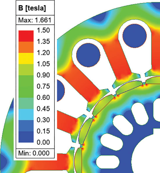
Figure 1.
Flux density distribution in the PMCM obtained from Ansys Maxwell simulations. The magnetic flux density (B-field) scale ranges from 0 T (blue) to 1.653 T (red). PMCM, permanent magnet cogging motor.
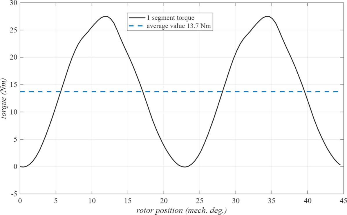
Figure 2.
Torque waveform and corresponding average value for a single PMCM segment derived from Ansys Maxwell simulations. The relationship between torque (Nm) and rotor position (mechanical degrees) is shown, with a mean value of approximately 13.7 Nm in the interval of 0–50 mechanical degrees. PMCM, permanent magnet cogging motor.
The average torque value per segment is close to 1.1 Nm lower than the analytical calculation result. The assumed flux density for the analytical linear model in the tooth is 1.25 T. However, the stator material is not linear; moreover, the value of flux density varies along the length of the tooth. All of this affects the FEA result.
3. Design Principles of PMCMs
3.1. Rated parameters of the prototype PMCM
Considering the availability of inverters, a nominal three-phase voltage of 400 V was selected at a frequency of 300 Hz. Therefore, the nominal synchronous rotational speed is:
The value of back-EMF = 400 V, for the assumed speed of 2,250 rpm, in a FEM simulation was achieved for the number of turns per tooth nt = 32, which gives the number of wires in the slot nz = 72. Based on the area of the slot Sz, the assumed fill factor of the slot kwz and the number of turns in the slot nt, the cross-section of the winding wire was calculated:
For the assumed current density jm = 6 A/mm2, the allowed rated current value is:
The internal structure of the machine, consisting of three stator and three rotor segments with their respective separating and positioning elements, has been integrated into a housing. The stator segments prepared for installation in the housing are shown in Figure 3b.
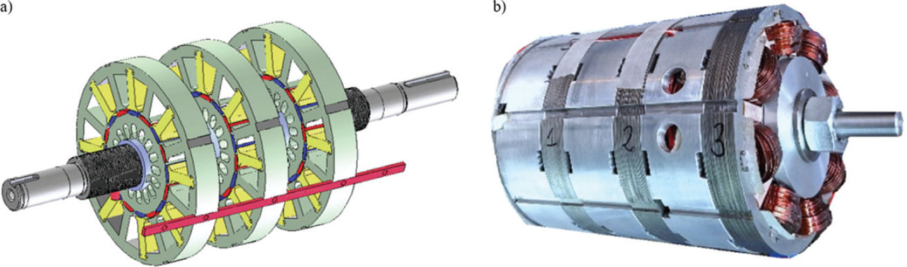
Figure 3.
(a) General concept of the rotor construction and (b) wound stator segments with separator elements prepared for assembly in the housing.
3.2. The geometry of the stator and rotor
The calculation results, verified by the FEA, were used to create a final PMCM prototype design. The principal objective of constructing the physical model was to investigate properties that are challenging to capture in analytical and FEM models, including machine efficiency, vibrations, and noise. The prototype was constructed based on the developed stator and rotor geometries, with dimensions depicted in Figure 4a and 4b, and each segment was 25 mm long.
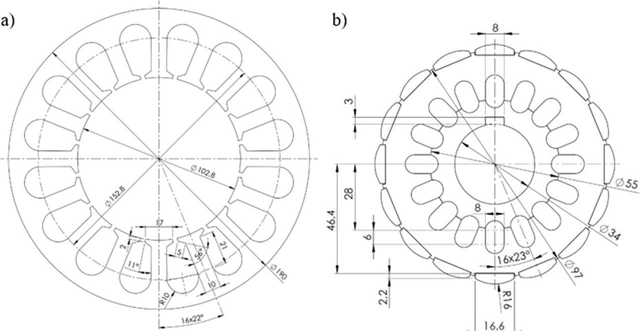
Figure 4.
(a) Stator geometry during the design process and (b) rotor geometry during the design process—all dimensions are in millimetres.
3.3. Selection of permanent magnets
In accordance with the analytical and FEA calculations, the prototype machine is assumed to contain 16 permanent magnets (8 pole pairs). The magnets are distributed on the rotor surface in a symmetrical manner, with a periodicity of 22.5°, and exhibit an alternating polarity in the north-south (N–S) direction. An important aspect is the selection of permanent magnets capable of ensuring reliable continuous-duty (S1) operation in industrial applications using only air cooling (Hanzhou et al., 2015; Hao and Kai, 2013; Remus et al., 2020).
The PMCM prototype was equipped with N38SH-type permanent magnets. The N38 indicates the magnet grade, with a maximum energy product of approximately 38 MGOe (Mega Gauss Oersted) (Arnold Magnetic Technologies, 2017). The magnetic parameters of this material are given in Table 2. N38SH magnets provide a good balance between performance and cost. They are widely available and less expensive than higher-grade magnets like N52, making them suitable for many industrial applications.
4. Motor Performance Analysis
4.1. Power circuit
The Danfoss FC302 (sold under the flagship name VLT® Automation Drive FC 302, Denmark) inverter was connected to a controlled AC–DC converter by a direct input to the inverter DC link. This approach was employed to increase the supply voltage amplitude of the tested PMCM. The Danfoss drive FC 302 implements conventional FOC to manage PMSMs. While the official documentation does not provide a detailed schematic of the internal FOC algorithm, it is reasonable to assume that it follows the classical FOC structure, as this is standard in modern industrial drives. The portable power meter Yokogawa WT1800 (Yokogawa Electric Corporation (Yokogawa Test & Measurement Corp., Japan) and Tektronix oscilloscope MDO3104 (Tektronix, Inc. a subsidiary of Fortive Corporation, USA) were used during all the tests. This indicates that the manufacturer implements vector control with encoder feedback. The encoder was connected to the Yokogawa power meter for efficiency calculation and to the FC302 for closed-loop control. This control strategy aligns with the conventional FOC strategy, involving Park and Clarke transformations, current decoupling, PI controllers in the d–q frame, and space vector pulse width modulation (SVPWM) voltage vector synthesis. The tested motor was mechanically coupled to a separately excited DC machine as a mechanical load (DCM)—model G 13.06 DA5 with 20 kW rated power. All load tests were carried out with the DC machine coupled to the tested motor.
4.2. Measurements and test setup
Communication with the inverter was established via the RS-232/USB interface provided by the manufacturer (Danfoss VLT® Automation Drive FC 302, Denmark). The voltages were measured using a Yokogawa voltage measurement element (up to 1 kV), whereas the currents exceeded the measurement range of the standard current elements (up to 5 A). The AC currents were measured by the Current Transducer IT 60-S ULTRASTAB (LEM Group is headquartered in Geneva (Meyrin), Switzerland). The IT 60-S Current Transducers have an accuracy of ± (0.05% of the measured value +30 μA) over a bandwidth from DC to 100 kHz. A torque sensor was used to measure the motor’s torque with a range up to 100 Nm (±0.5%) (NCTE AG — Torque Sensor Series 2300, Germany), and an incremental encoder was employed to determine the speed of the drive system.
4.3. Back-EMF measurement
The primary waveform used to assess whether the machine prototype meets the design requirements is the back-EMF, obtained from the FEM simulation and measured during no-load operation. Figure 5 compares several periods of the simulated and measured phase-voltage waveforms.
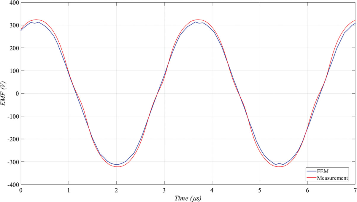
Figure 5.
Comparison of simulated and measured back-EMF.
The RMS value of the measured back-EMF is 235 V, which is approximately 1.5% higher than the design value. This discrepancy is most likely attributable to inaccuracies in the material parameters adopted in the simulation, particularly the magnetic characteristics of the electrical steel laminations and permanent magnets. Nevertheless, the measured waveform closely matches the simulated one in terms of shape, confirming that the machine prototype successfully meets the design requirements.
4.4. Torque constant measurement
Figure 6 illustrates the correlation between the measured electromagnetic torque Te and the stator phase current IRMS. The characteristic was quantified utilising a torque sensor, with the PMCM load increasing from idle current to twice the rated current. Relative error is shown in Figure 6. The relative error was calculated by:
whereTe is measured electromagnetic torque and
Teav is calculated electromagnetic torque.
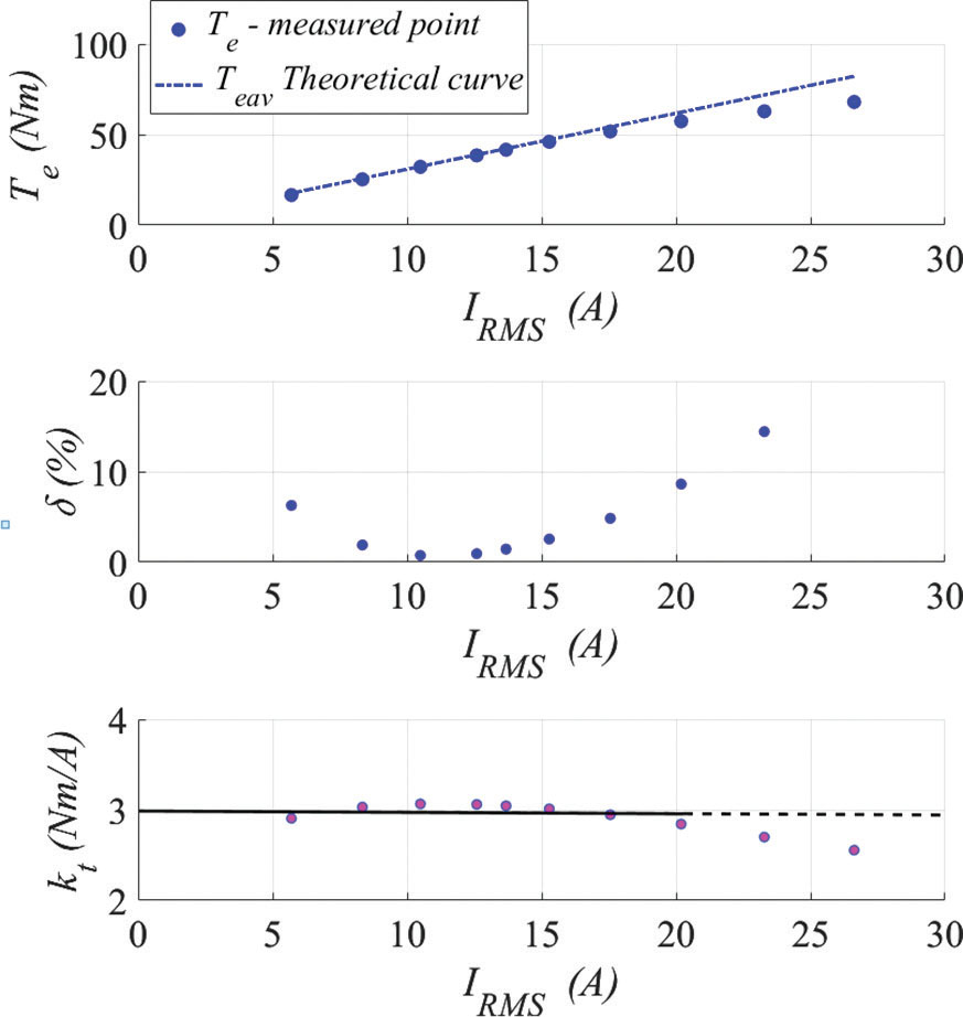
Figure 6.
Motor torque (Nm) vs motor RMS current (A) with relative error and torque constant.
Up to approximately 15 A, the measured and calculated torque values are in agreement, exhibiting a linear variation in proportion to the stator current. The stator iron has a finite magnetic permeability, and at high currents, the magnetic field in the stator core saturates, meaning it cannot effectively carry additional magnetic flux. Due to the phenomenon of saturation of the magnetic core, the measured torque does not increase proportionally to the current (Figure 6).
The agreement between the torque measurement results and the calculations for the linear range of the magnetic circuit confirms the validity of the torque equation derived in Chapter II. The torque constant for PMSMs is often expressed in terms of the peak current for simplicity, but many manufacturers specify kt based on RMS current for sinusoidal waveforms. For the proposed PMCM (Figure 6—linear part of the characteristic Te vs IRMS) with preferred field-oriented control and sinusoidal current, the RMS-based torque constant was calculated by:
The kt−RMS value for the linear part is approximately 3 Nm/A. The torque constant of different servo motors must be defined by one standard peak or RMS current to provide a valid comparison.
4.5. Idle losses of the prototype
Measuring idle losses vs speed (Figure 7) was the next step in evaluating the efficiency and baseline performance of the PMCM. Idle losses represent the energy consumption of the motor when it is running without any external load, and they provide valuable information about the motor’s intrinsic losses. Motor AC input power was measured using a Yokogawa WT1800 power meter. The principal components of idling losses are mechanical losses, which are contingent upon rotational speed, and core losses, which are influenced by both voltage and frequency of the power supply.
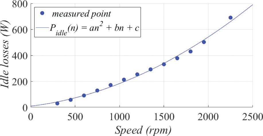
Figure 7.
Motor-run power losses (W) of the tested motor vs motor speed (rpm) during free run (idle losses).
As expected, the idle losses (Figure 7) increase non-linearly with current and the approximation with the second-order polynomial function of the form:
wheren is motor speed (rpm),
a is the coefficient for quadratic losses—aerodynamic drag. Aerodynamic drag losses increase with the square of the motor’s speed,
b is the coefficient value for linear losses. Friction losses increase linearly with motor speed, especially in bearings, and
c are constant losses, which are referred to as core losses and standby state losses. All losses remain relatively unchanged regardless of the motor’s speed.
The selected polynomial with coefficients a = 9.258e−05, b = 0.08, and c = 9.12 allows the fitting curve to achieve R2 factor close to 0.99. The term an2 reflects losses due to aerodynamic drag, which scale with the square of the motor speed (n2). At high motor speeds, the quadratic component becomes the dominant contributor to idle losses. This is because aerodynamic drag increases exponentially with speed, making motors less efficient in high-speed scenarios if this coefficient is significant. At medium motor speeds, the linear term bn is the dominant contributor to idle losses. This aligns with typical scenarios where bearing friction and other resistive forces play a significant role. The constant term c, representing the core and standby losses, is most significant at low motor speeds, where other loss components (an2 and bn) are relatively small.
4.6. Efficiency
In this section, the efficiency curves with peak efficiency were measured for different load and speed conditions. Figure 8 presents the calculated efficiency data with fit approximation curves. Efficiency measurements were performed using the direct method:
wherePAC is motor input electrical power (W) and
PM is motor output mechanical power (W).
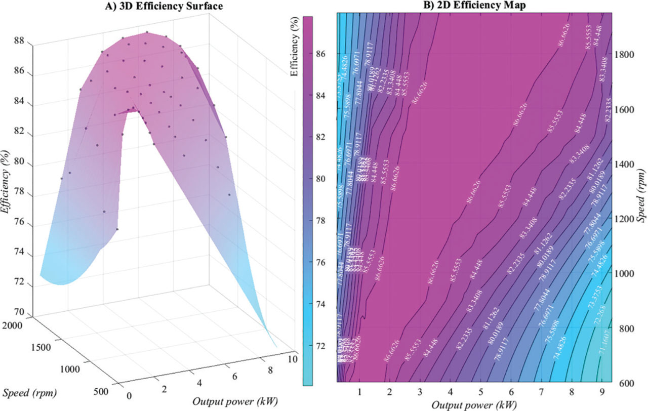
Figure 8.
Efficiency vs output power (in range: 0–10 kW) vs speed (in range: 600–1875 rpm).
A key factor contributing to the reduced efficiency is winding losses. As indicated in the introduction, the PMCM prototype features longer windings than conventional TFMs. In order to compare these two constructions, certain assumptions must be made:
the stators of the same diameter are compared; that is, the diameter of the TFM machine segment coil is equal to the slot distribution diameter in the flat core (RCu = 152.8 mm for the tested prototype, see Figure 4a),
the cross-section of the TFM coil is equal to the copper cross-section in the PMCM slot.
Under these assumptions, the winding resistance and, thus, the losses depend linearly only on the winding length, which should, therefore, be compared. The copper length of the TFM coil for parameters corresponding to the prototype:
The copper length of the PMCM coil:
whereIFe is the stack length of a single segment (25 mm) and
Q is the number of slots (16).
Thus, for the adopted assumptions:
The above calculations show that, under the adopted assumptions, the PMCM motor winding is approximately twice as long as that of the TFM winding, directly resulting in approximately twice the winding losses. It should be noted that these calculations are representative only for this specific design with a given number of slots.
4.7. Temperature
The PMCM prototype is equipped with PT100 temperature sensors installed inside each winding and on each core, allowing for a precise measurement of the temperature rise. All thermal measurements were conducted at an ambient temperature of approximately 23°C. During the tests, forced-air cooling was provided by a dedicated fan driven by an external motor, which made the cooling airflow independent of the rotational speed and the operating point of the PMCM. The prototype uses magnets with a maximum operating temperature of 150°C (Arnold Magnetic Technologies, 2017). In practice, it is recommended that the winding temperature should be sufficiently lower with a safety margin of 10–20°C (Hanzhou et al., 2015). For an assumed current rating of 14.2 A, the temperature at the highest point exceeded this safety limit. Upon reducing the current to 12 A, the temperature stabilised at approximately 130°C (266°F), which was deemed a safe value. To ensure a sufficient safety margin, the motor operating temperature should not exceed 130°C to reduce the risk of irreversible degradation or demagnetisation of the N38SH magnets. N38SH magnets have a temperature coefficient of about −0.12% per °C for residual induction and −0.55% per °C for coercivity (Arnold Magnetic Technologies, 2017). This means that for a 1°C increase in temperature, the magnetic properties of the material will decrease. This should be taken into consideration if the motor is subjected to high temperatures over time. Figure 9 illustrates the temperature profile of the winding and core. The recorded temperature distribution in the segments was uneven. In general, temperatures in the segment located in closer proximity to the fan were observed to be slightly lower than those of the segment on the opposite side.
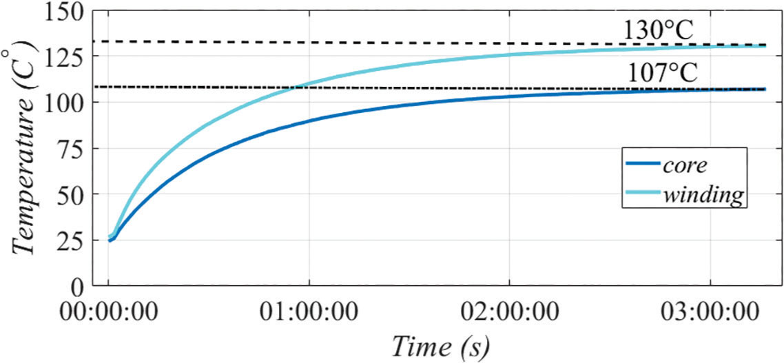
Figure 9.
Temperature change in the motor (core and winding) during operation.
Possible options to mitigate these issues in future designs, especially in applications where high winding temperatures are a concern (electric vehicle or industry), are listed below:
Improvement of the existing forced-air cooling system by using a fan with a higher airflow rate and optimising the airflow distribution around the stator segments,
Change the cooling system to an active water flow cooling mechanism or an oil cooling system, and
The use of magnets of higher grade than the N38SH used in the prototype could help maintain high efficiency and reduce motor losses.
The high winding temperature indicates that copper losses are the dominant heat source in the PMSM and may reduce insulation lifetime and overall machine reliability if not effectively dissipated (Gundabattini et al., 2021). Based on Tong et al., 2019, 50% of losses in PMSM-type motors are stator-related losses. Stator optimisation is critical for high-efficiency design. Tong et al. (2019) address the critical issue of material selection for pole spacers in high-speed PMSMs, focusing on minimising temperature rise and thermal stress. Plastic as a spacer results in the lowest temperature rise for the magnets, while Ti-alloy minimises the thermal stress on the sleeve. The selection of spacer materials should balance both factors—magnet temperature rise and sleeve thermal stress. Among the four materials analysed, Al-alloy emerges as the optimal choice. To improve thermal performance, enhanced cooling techniques such as optimised water-jacket cooling, direct end-winding cooling, and the use of thermally conductive potting or encapsulation materials can significantly reduce the winding hot-spot temperature and improve temperature uniformity (Song et al., 2023). Furthermore, hybrid cooling approaches that combine liquid cooling with direct winding cooling have been shown to provide superior heat dissipation for high-power-density PMSMs and should be considered in future designs (Gundabattini and Mystkowski, 2022).
4.8. Acoustic noise
The acoustic noise of PMSMs is mainly caused by harmonics of electromagnetic force, mechanical vibration, and structural resonance, which become more pronounced in high-speed operation (Zhu and Howe, 2000). Effective noise mitigation techniques include rotor and stator skewing, optimisation of slot–pole combinations, reduction of torque ripple through electromagnetic design optimisation, and structural reinforcement to avoid resonance, all of which have been demonstrated to reduce vibration and acoustic noise in similar PMSMs (Gieras et al., 2005). Compared with similar permanent magnet machines reported in the literature, these approaches provide improved noise characteristics without significantly compromising electromagnetic performance and could be considered in future work (X. Liu, et. al., 2021). Measurements were conducted when the PMCM was supplied with a voltage of fs = 170 Hz, under a rated torque load. The rotational frequency for this case is:
Figure 10 illustrates the amplitude spectrum of the noise recorded during the operation of the machine under the aforementioned conditions. The dominant frequencies visible in the spectrum are fa1 = 340 Hz and fa2 = 680 Hz, with the highest amplitude. These frequencies are closely related to the rotational frequency and the number of poles:
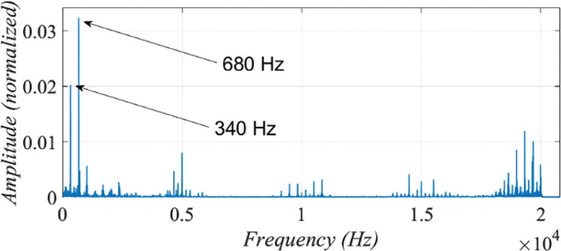
Figure 10.
Amplitude spectrum of noise in the range of 0 kHz up to 20 kHz with zoomed frequency below 1.5 kHz.
This phenomenon is known as electromagnetic noise and is common in PMSMs (Wan et al., 2016). The generation of these dominant frequencies can be attributed to the fact that in the PMCM, the number of stator teeth is equal to the number of poles (magnets). In this case, radial stresses are generated in each segment, which induce vibrations in the housing and thereby generate variations in sound pressure. The magnitude of the fa2 harmonic is larger than the magnitude of the fa1 fundamental frequency; this suggests that the second harmonic is being amplified by some specific mechanism in the motor system and can be caused by:
Slot Harmonics—These harmonics arise due to the interaction between the stator slots and the rotor magnetic field. They can generate vibrations and acoustic noise at multiples of the fundamental frequency, potentially emphasising specific harmonics, like the second.
Resonance Effects—The motor or its mounting structure might have a natural frequency close to fa2, causing a resonance effect that amplifies this frequency.
Unbalanced Forces—Rotor eccentricity (static or dynamic) or imbalanced forces in the rotor can lead to amplified second harmonic noise due to uneven air-gap flux distribution.
The measured noise intensity generated by the PMCM prototype in this operating condition is 80.2 dB. Measurements were performed at a distance of 1 m from the motor surface. The test was performed using an HT602B sound level meter with ±1.5 dB (94 dB 1 kHz), ±5 dB (94 dB 8 kHz) uncertainty. This value is quite high; however, it is within the 75–85 dB specified in IEC Standard 60034-9:2021 for this power range.
Rotor holes and non-smooth rotor structures generate noise and vibration, which can be mitigated by addressing structural factors. The proposed rotor design optimisation strategies to reduce these issues are to make the rotor structure as symmetric as possible, in order to minimise mechanical imbalance and radial force fluctuations.
The other option is the use of a modified active FOC algorithm (Nägelkrämer et al., 2018). The study focuses on reducing torque ripple and radial force harmonics, which are primary contributors to acoustic noise and vibrations in these motors, by applying dynamic programming to optimise control strategies that minimise noise characteristics of PMSM.
5. Conclusion
The PMCM represents an innovative development of the TFMs, optimised and validated through rigorous numerical simulations. One of the main advantages of this design, which distinguishes it from conventional TFM solutions, is the improved utilisation of both the magnetic circuit and the permanent magnets. In the developed topology, the use of a flat core reduces the leakage flux of the magnets. At the same time, this increases the developed electromagnetic torque, since it is produced by all magnets simultaneously, whereas in a conventional TFM, the flux of every second pair of magnets is linked with the winding.
However, the proposed design is inherently more complex than traditional alternatives, as it requires high-precision assembly of the individual stator segments. This complexity led to several construction-related challenges in the prototype. In particular, the machine exhibited excessive winding temperatures at the target current density and generated a high level of acoustic noise, indicating key areas that require further thermal and structural refinement.
The primary applications, considering the features of the developed machine, will be those requiring a drive with increased torque density. The scaling of the PMCM machine, as in most machines, can be achieved by increasing its diameter or length of the segments. However, a unique feature is the ability to scale the machine by increasing or decreasing the number of segments, thereby changing the number of phases or simply multiplying the number of segments.