
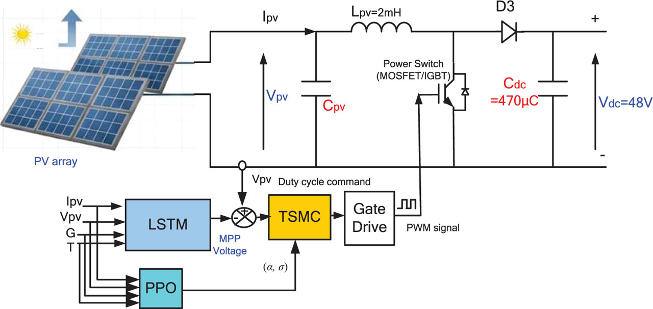
Figure 1.
Overall architecture of the proposed LSTM–PPO–TSMC-based MPPT control scheme for a PV system. IGBT, Insulated Gate Bipolar Transistor; LSTM, long short-term memory; MOSFET, Metal-Oxide-Semiconductor Field-Effect Transistor; MPP, Maximum Power Point; MPPT, maximum power point tracking; PPO, proximal policy optimisation; PV, photovoltaic; PWM, pulse width modulation.
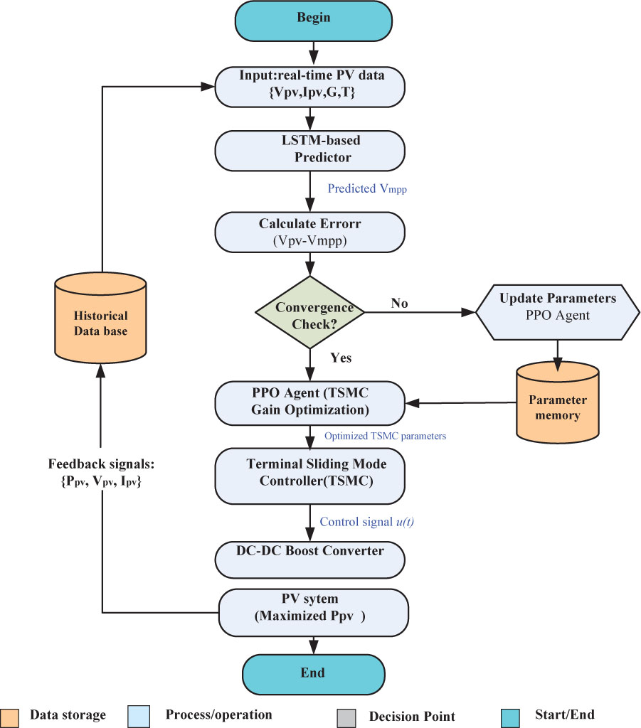
Figure 2.
Flowchart of the proposed hybrid LSTM–PPO–TSMC MPPT. LSTM, long short-term memory; MPPT, maximum power point tracking; PPO, proximal policy optimization.
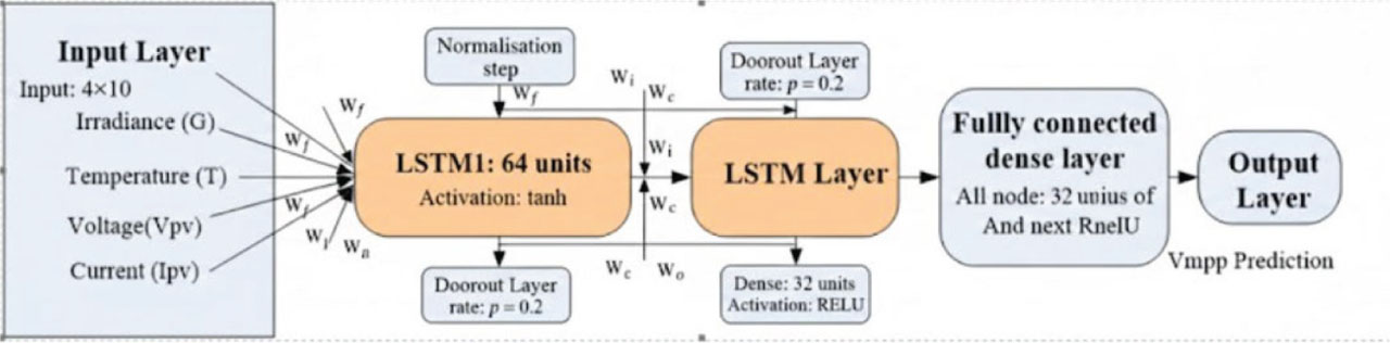
Figure 3.
Architecture of the LSTM model for the prediction of maximum power voltage VMPP. LSTM, long short-term memory; VMPP, maximum power point voltage prediction.
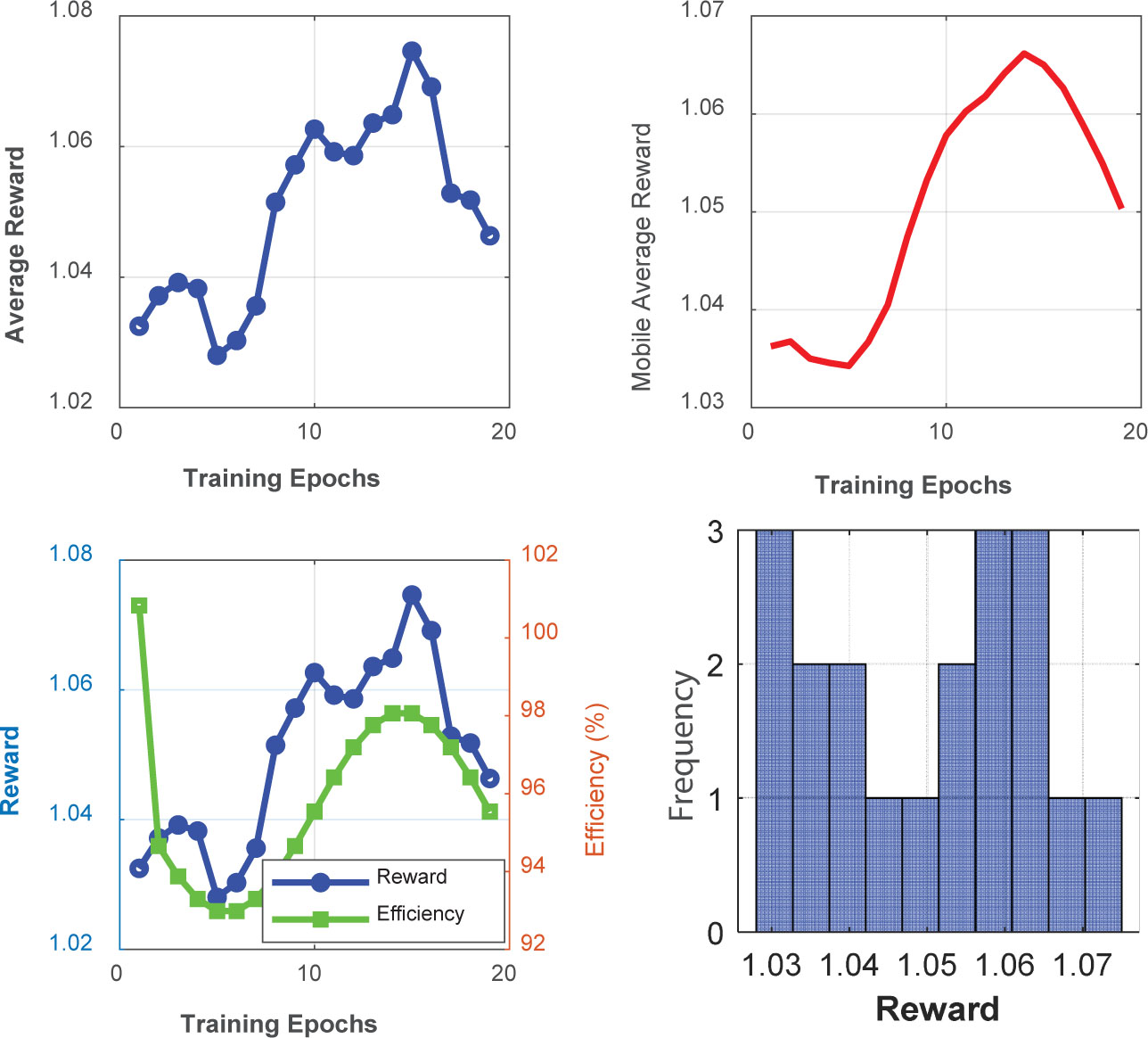
Figure 4.
PPO Agent training performance analysis. PPO, proximal policy optimisation.
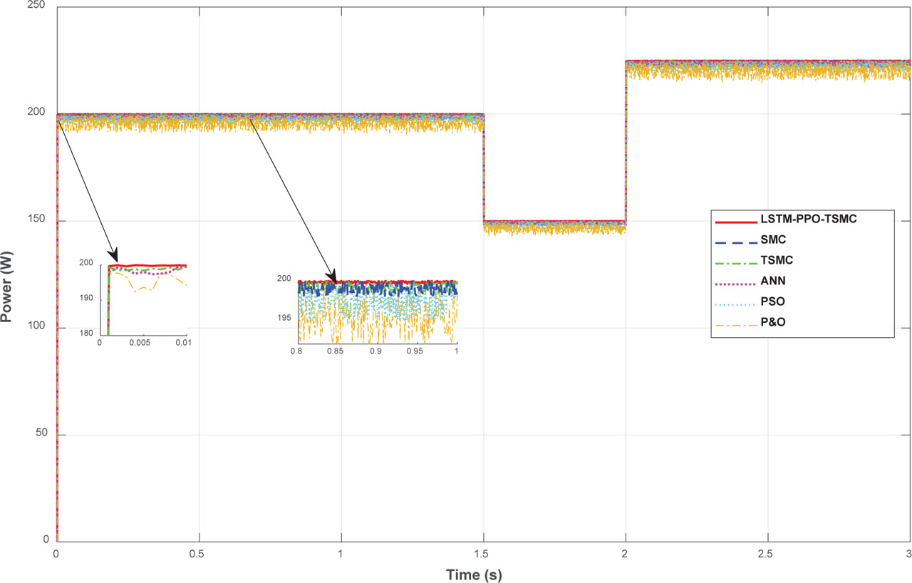
Figure 5.
Power comparison under variable irradiation. ANN, artificial neural networks; LSTM, long short-term memory; P&O, perturb & observe; PPO, proximal policy optimisation; PSO, particle swarm optimisation.
Table 1.
Parameters used for comparative MPPT methods
| Method | Main parameters |
|---|---|
| SMC | λ = 5, switching gain = 10 |
| TSMC | α = 0.8, σ = 0.5 |
| ANN-MPPT | 1 hidden layer, 10 neurons, tanh |
| PSO-MPPT | Particles = 10, w = 0.7, c1 = c2 = 1.5 |
| P&O | Step size = 0.01 |
| Proposed | LSTM (2 × 64), PPO adaptive α,σ |
Table 2.
Performance metric for different MPPT algorithms
| MPPT method | Average error | Response time (ms) | Oscillations | Efficiency (%) |
|---|---|---|---|---|
| Classic SMC | 0.65 | 120 | Low | 94.3 |
| TSMC | 0.52 | 100 | Very low | 95.8 |
| ANN-MPPT | 0.48 | 110 | Moderate | 96.1 |
| PSO-MPPT | 0.55 | 180 | High | 95.2 |
| TSMC + PPO + LSTM (proposed) | 0.25 | 65 | Negligible | 97.4 |
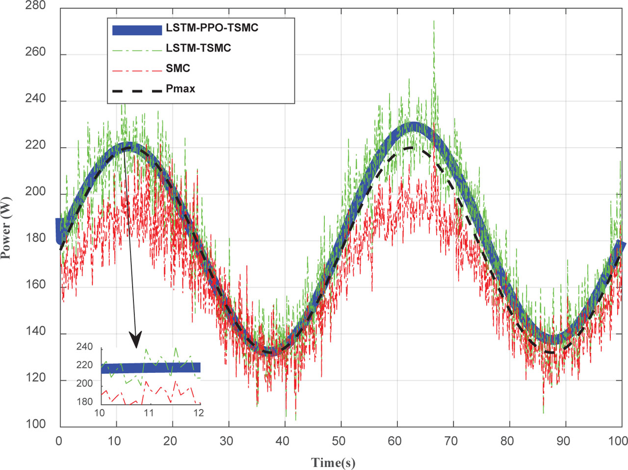
Figure 6.
Power comparison of the MPPT algorithms under fluctuating irradiance. LSTM, long short-term memory; MPPT, maximum power point tracking; PPO, proximal policy optimisation.
Table 3.
Performance metric for different MPPT algorithms
| MPPT method | Settling time (ms) | Overshoot (%) |
|---|---|---|
| Classic SMC | 160 | 9.5 |
| LSTM + TSMC | 85 | 3.8 |
| LSTM + PPO + TSMC (proposed) | 55 | 1.6 |
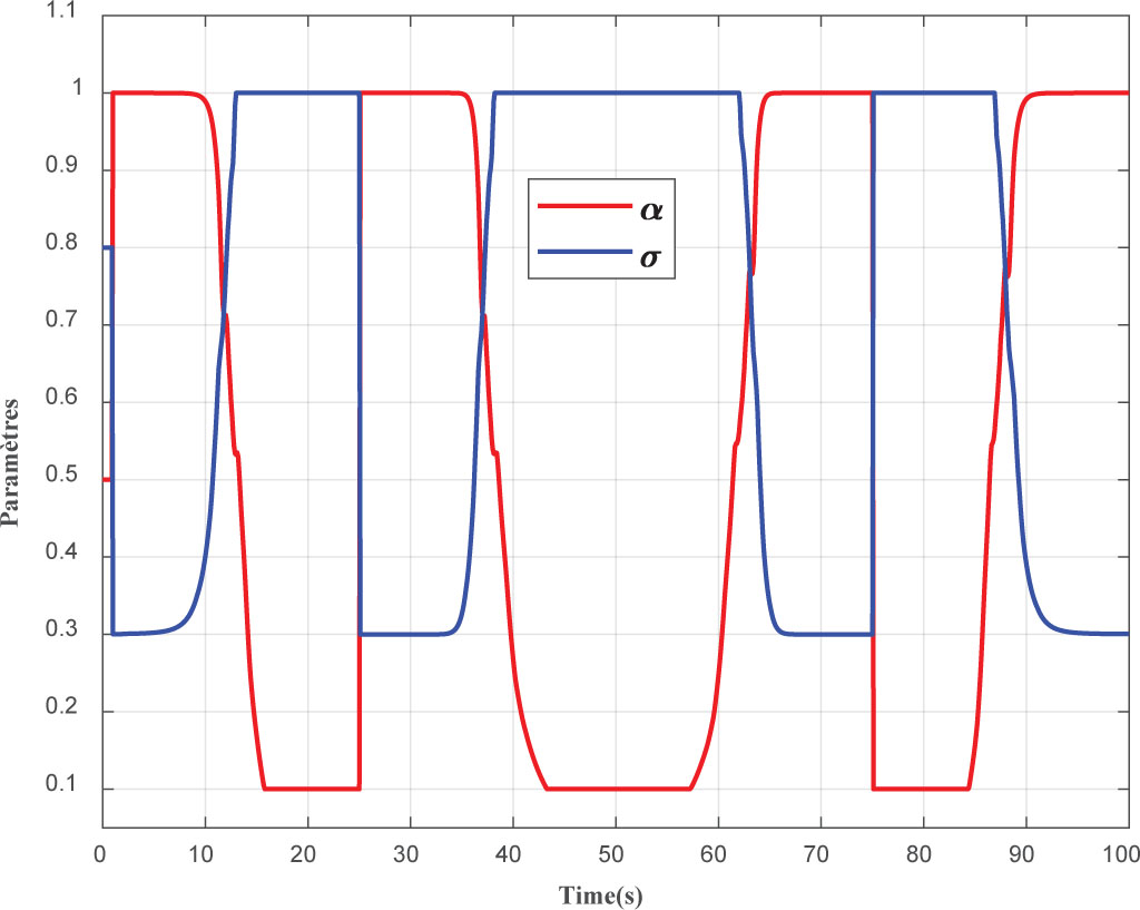
Figure 7.
Dynamic adjustment of TSMC parameters by the PPO Agent. PPO, proximal policy optimisation.
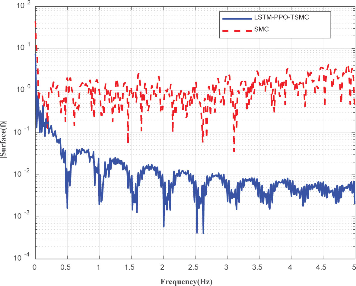
Figure 8.
Frequency-domain analysis of control signal chattering. LSTM, long short-term memory; PPO, proximal policy optimisation.
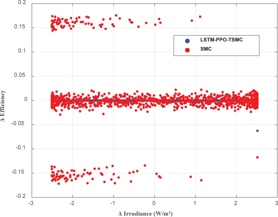
Figure 9.
Efficiency deviation vs. irradiance change. LSTM, long short-term memory; PPO, proximal policy optmisation.
Table 4.
Comprehensive computational complexity comparison of MPPT methods
| MPPT method | Operations/step | Execution Time (ms) | Memory (KB) | Update rate | Relative cost |
|---|---|---|---|---|---|
| Classic SMC | 32 | 0.02 | 2 | Full switching | 0.08× |
| TSMC | 64 | 0.05 | 4 | Full switching | 0.13× |
| ANN–MPPT (3-layer) | 1,280 | 0.18 | 12 | 1 kHz | 0.70× |
| PSO-MPPT (10 particles) | 3,200 | 0.35 | 28 | 100 Hz | 3.10× |
| Full DRL (online) | 18,000 | 2.10 | 256 | 10 Hz | 11.3× |
| LSTM–PPO–TSMC (proposed) | 4,416 | 0.45 | 38 | 1 kHz | 1.0× |