
Table 1.
Literature review.
| Reference | Focus area | Key contribution | Limitations |
|---|---|---|---|
| Marquardt (2001) | MMC fundamentals | Introduced MMC topology for scalable high-voltage applications | Early work lacked detailed control strategies for circulating currents |
| Rodriguez et al. (2009) | Multilevel converters | Overview of multilevel converter topologies and their industrial applications | Limited focus on MMC -specific challenges like capacitor balancing |
| Dekka et al. (2017) | MMC evolution | Comprehensive review of MMC topologies, modulation and control methods | Did not address advanced harmonic suppression techniques |
| Tu et al. (2011) | Circulating current control | Proposed PI controllers in double-fundamental rotating frame for harmonic reduction | Ineffective under unbalanced grid conditions |
| Li et al. (2013) | Passive control method | Introduced arm inductance/resistance for circulating current suppression | High voltage disturbances and instability risks |
| Zhang et al. (2014) | Hybrid control | Combined PI and repetitive controllers for harmonic elimination | Complex tuning, limited transient performance |
| He et al. (2015) | Series PI-repetitive control | Enhanced PI transient performance with repetitive steady-state control | Restricted bandwidth, unsuitable for non-integer harmonics |
| Bergna et al. (2013) | Energy-based control | Decoupled double synchronous frame for sequence component regulation | High computational complexity, limited to three-phase systems |
| Proposed method | EOGI-based control | Parallel multi-harmonic EOGIs (2nd, 4th and 6th-order) | Requires ISE-optimised gains but achieves stability via Popov criterion |
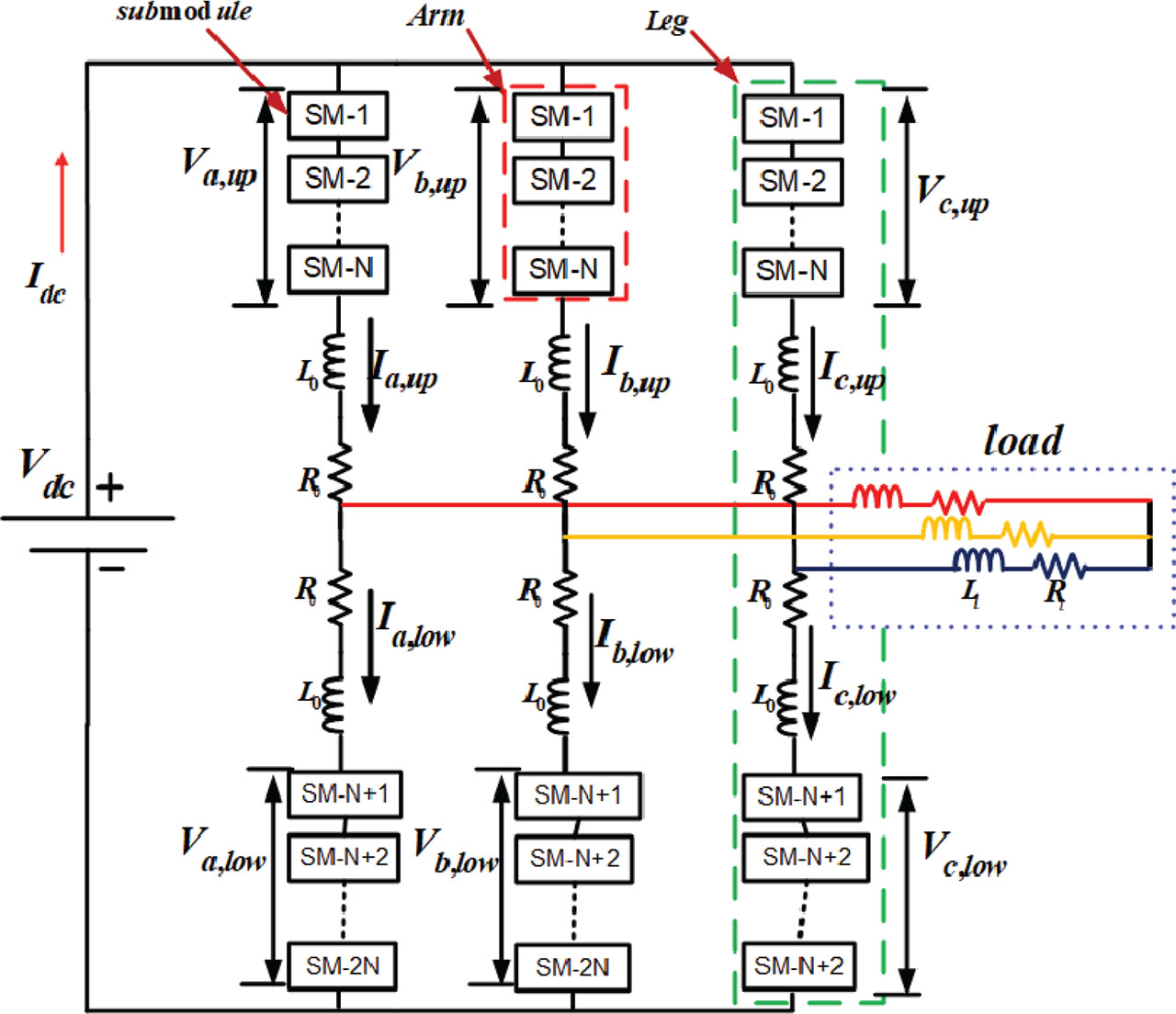
Figure 1.
Basic configuration of three-phase MMC. MMC, modular multilevel converter.
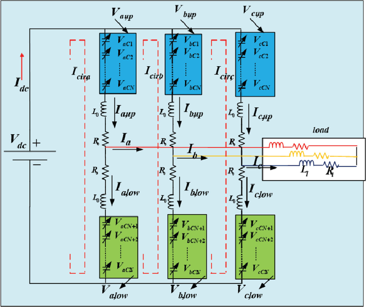
Figure 2.
Equivalent diagram of a 3-phase MMC. MMC, modular multilevel converter.
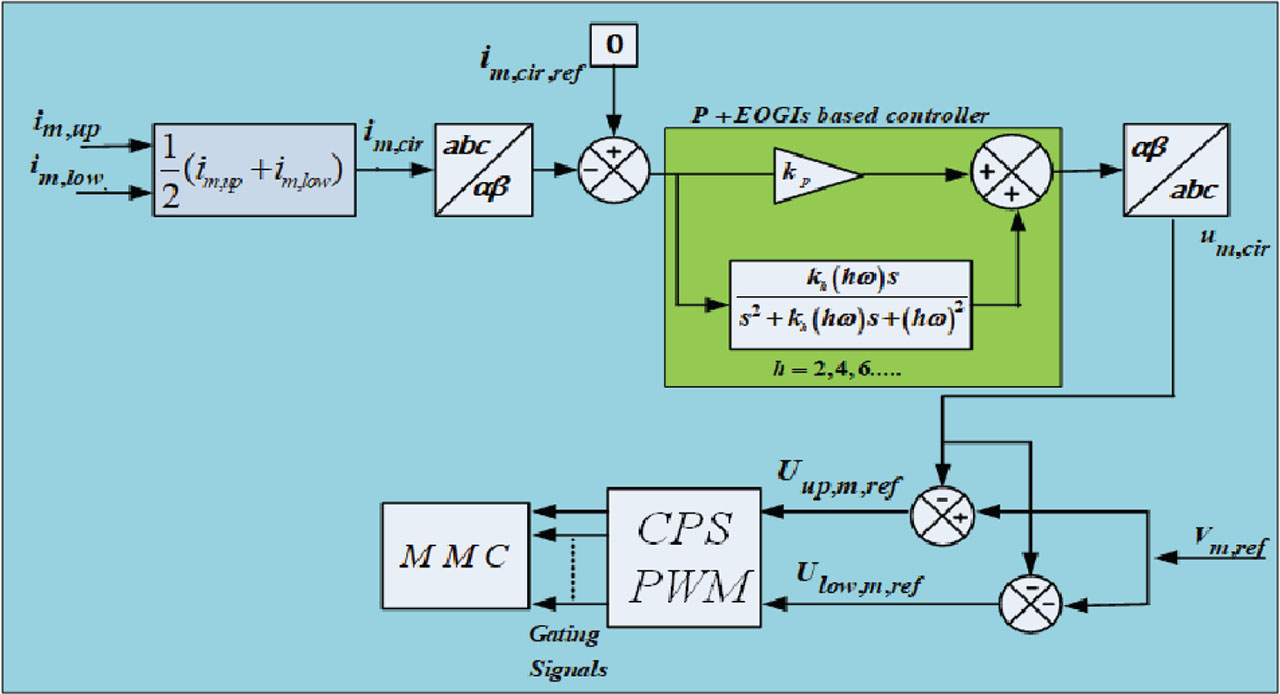
Figure 3.
Block diagram of proposed P + EOGIs based controller for minimisation of circulating current control. EOGIs, extended order generalised integrator; MMC, modular multilevel converter; PWM, pulse width modulation.
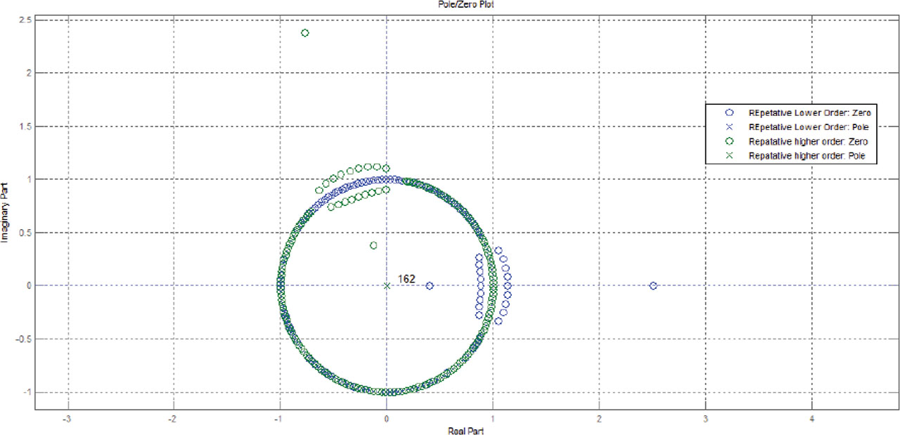
Figure 4.
Proposed controller used for MMC showing pole/zero responses. (X-axis-Real Part and Y-axis-Imaginary part). MMC, modular multilevel converter.
Table 2.
Simulation parameters used in proposed configuration.
| S. no | Parameter | Value |
|---|---|---|
| 1 | Rated active power | 20 MW |
| 2 | Rated reactive power | 6.6 VAR |
| 3 | DC supply | 33 kV |
| 4 | DC link capacitor value | 300 µF |
| 5 | Converter output voltage RMS | 11 kV |
| 6 | Number of sub-modules per arm | 6 |
| 7 | Each sub-module capacitor value | 0.03 F |
| 8 | Each sub-module capacitor voltage | 5,500 V |
| 9 | Resistance of arm | 0.01 Ω |
| 10 | Inductance of arm | 5 mH |
| 11 | Line frequency | 50 Hz |
| 12 | Carrier switching frequency | 2 kHz |
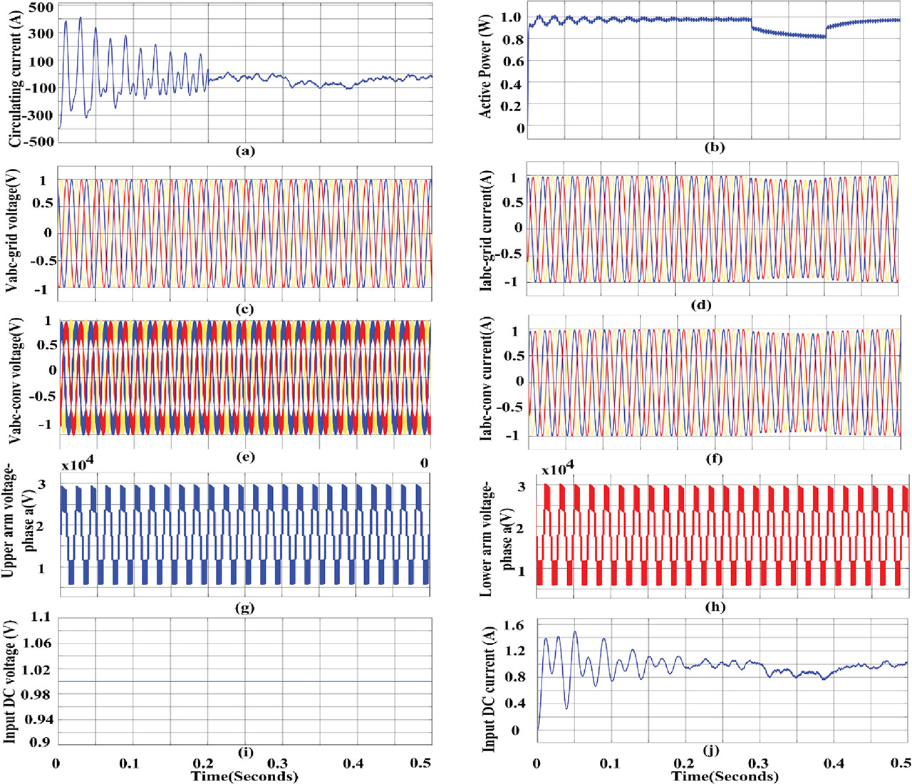
Figure 5.
System executed with conventional PI-controller for resistive load (a) circulating currents (b) active power output (c) output voltage of grid and (d) output current of grid (e) converter output voltage (f) converter output current (g) upper arm voltage of phase-a (h) lower arm voltage of phase-a (i) input DC voltage (j) input DC.
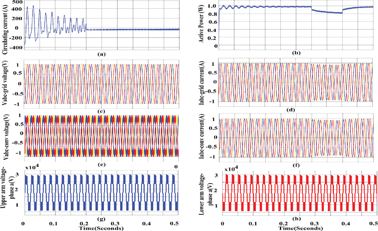
Figure 6.
System executed with proposed controller for resistive load (a) circulating currents (b) active power output (c) output voltage of grid and (d) output current of grid (e) converter output voltage (f) converter output current (g) upper arm voltage of phase-a (h) lower arm voltage of phase-a.
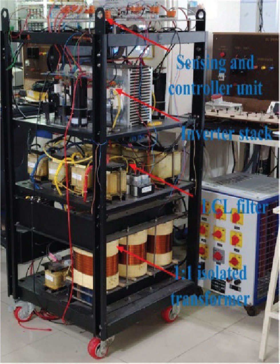
Figure 7.
Experimental hardware setup of proposed system.
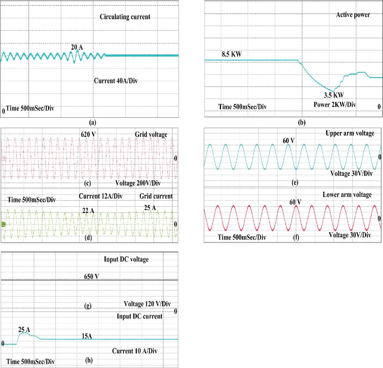
Figure 8.
System executed with proposed controller for resistive load (a) circulating currents (b) output voltage of grid and (c) output current of grid (d) active power output (e) upper arm voltage of phase-a (f) lower arm voltage of phase-a (g) input DC voltage (h) input DC.
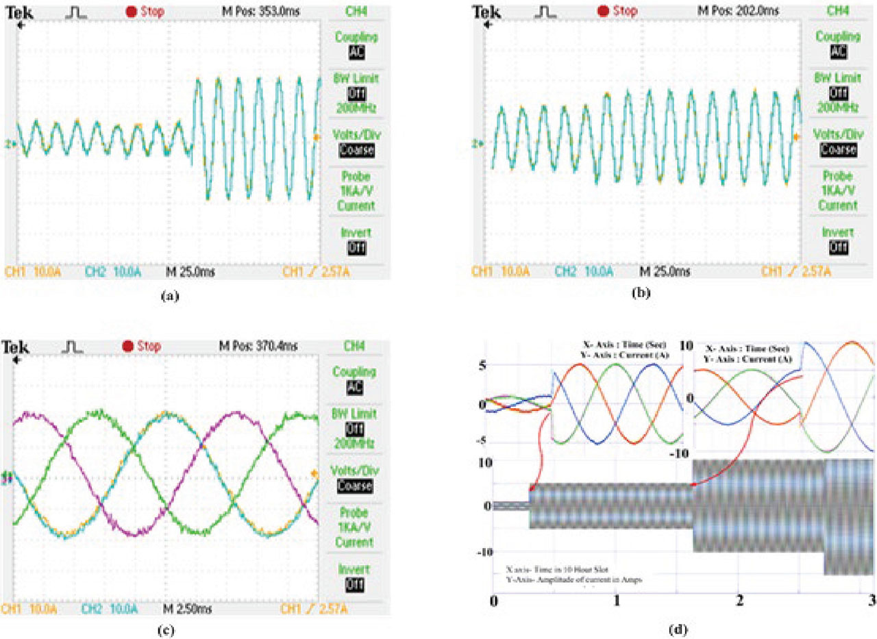
Figure 9.
Proposed system with (a) RL load (b) non-linear loads (c) non-linear loads and implementation of EOGI for harmonic mitigation (d) three phase currents during references. EOGI, extended order generalised integrator; RL, resistive-inductive load.
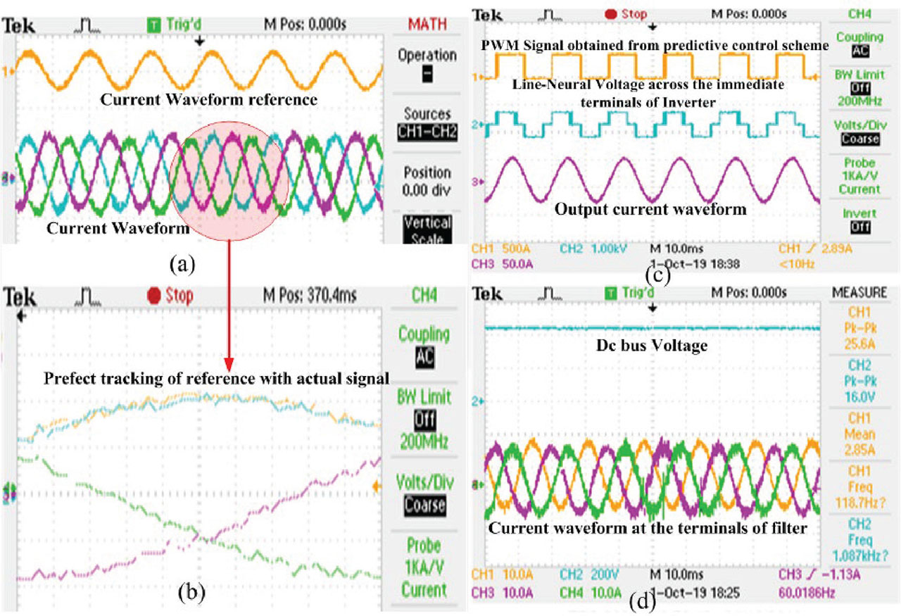
Figure 10.
Waveforms obtained using OPAL RT (New Delhi, India), and MATLAB and their comparison (a). Current waveforms (b). PWM signals and voltage waveforms (c). Tracking between them (d). DC bus voltage and its effect in variations. PWM, pulse width modulation.