
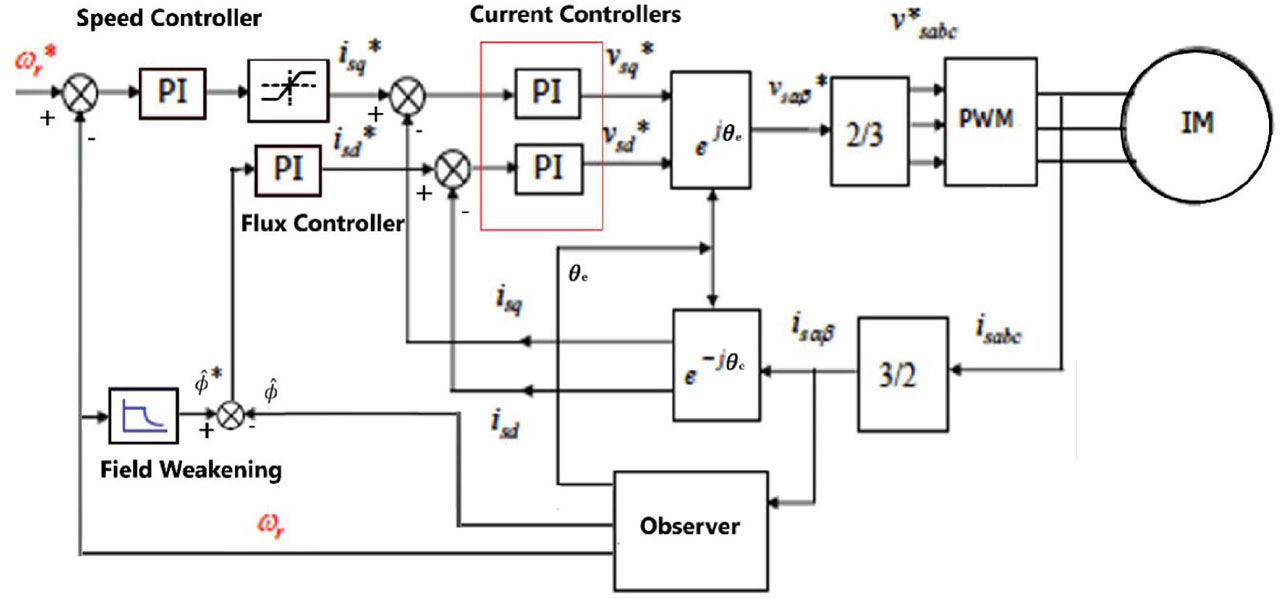
Figure 1.
Block diagram of induction machine sensorless control scheme of the DRFO method. DRFO, direct rotor flux orientation.
Table 1.
Parameters of Induction motor model used.
| Motor parameters | Values |
|---|---|
| Rs | 2.3 |
| Ls | 0.261 H |
| Lr | 0.261 H |
| P | 4 |
| B | 0.0286 kg · m−2 |
| J | 0.02 kg · m−2 |
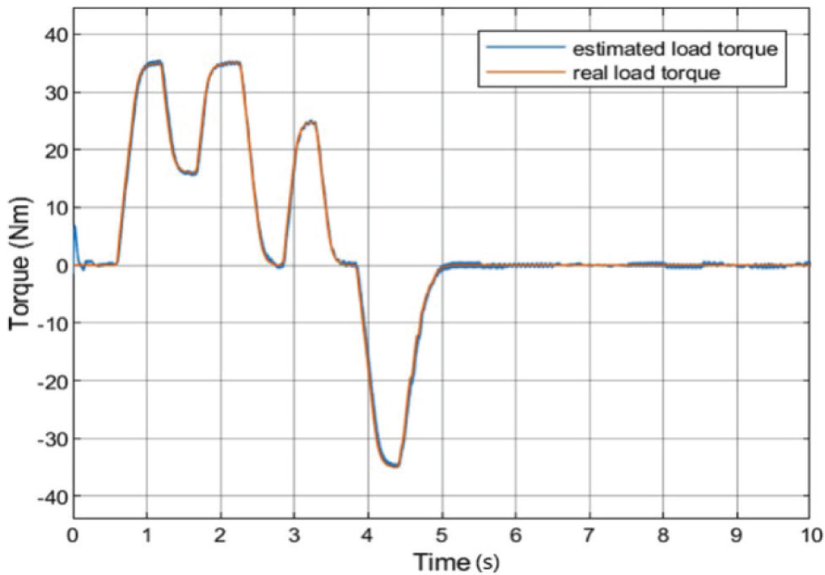
Figure 2.
Varying load torque.
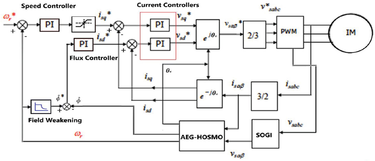
Figure 3.
Block diagram of Induction machine sensorless control scheme with proposed SOGI-HOSM. SOGI-HOSM, second-order generalised integrator-higher-order sliding mode.
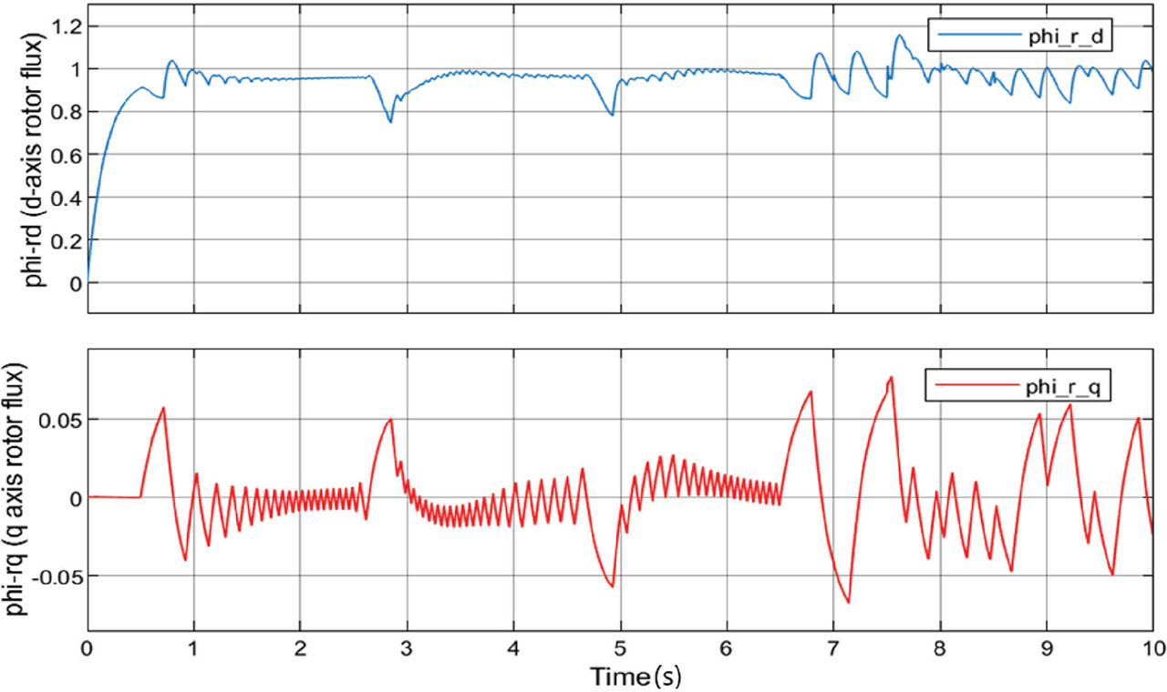
Figure 4.
Rotor fluxes in d–q reference frame.
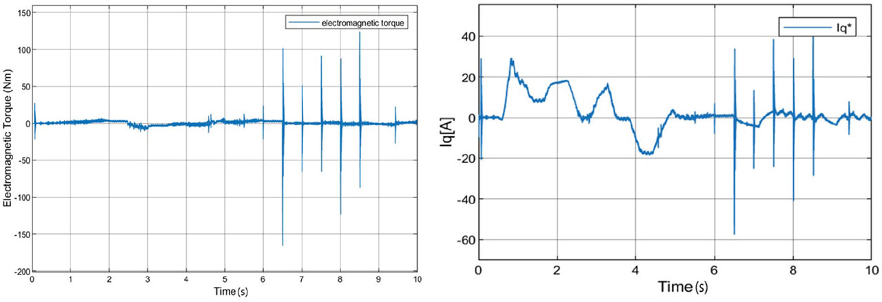
Figure 5.
Electromagnetic torque (on the left) and the commanded stator current on the q-axis (on the right).
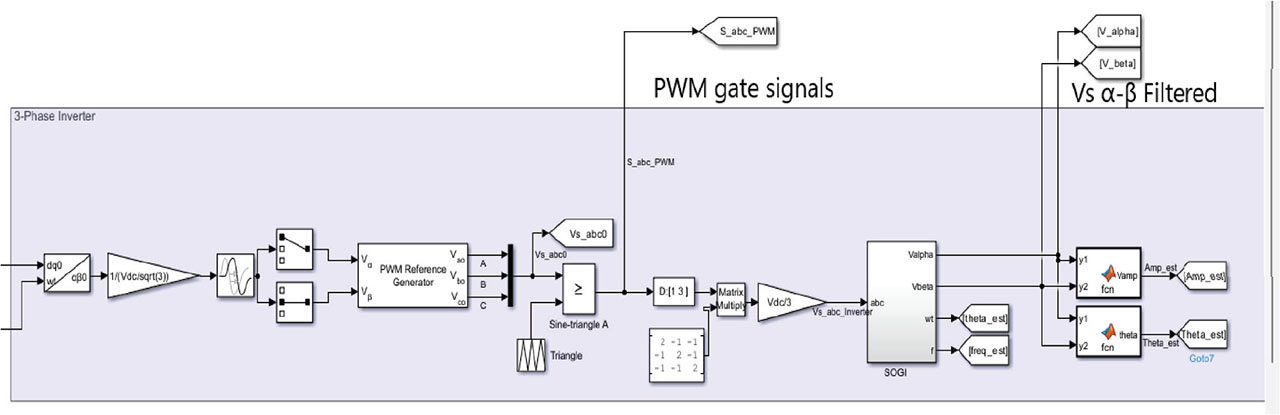
Figure 6.
MATLAB/Simulink implementation of the filtering of and by the SOGI topology. SOGI, second-order generalised integrator.
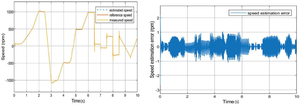
Figure 7.
Performance of the proposed SOGI-HOSM at varying speed commands. SOGI-HOSM, second-order generalised integrator-higher-order sliding mode.
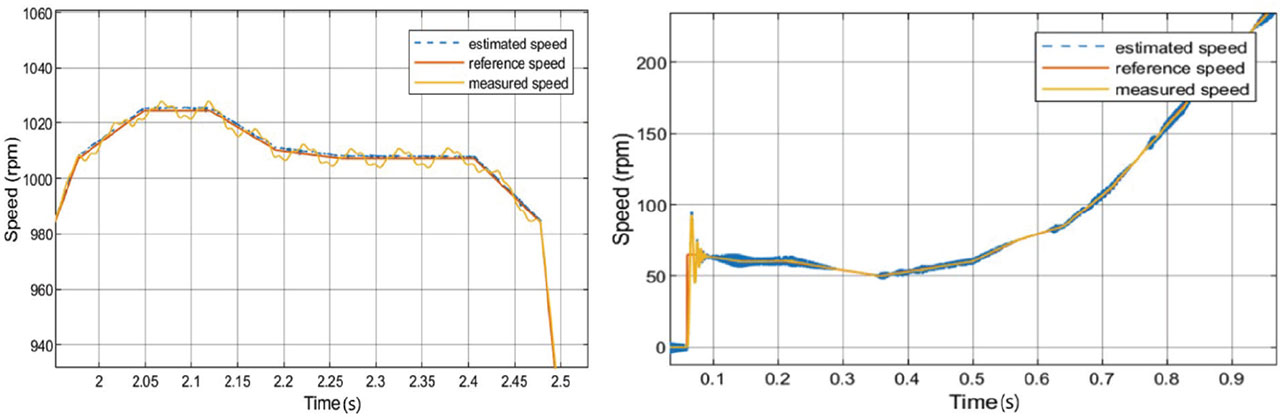
Figure 8.
Zoomed-in version of the performance of the proposed SOGI-HOSM during frequency ramps (on the left) and at low speeds (on the right). SOGI-HOSM, second-order generalised integrator-higher-order sliding mode.
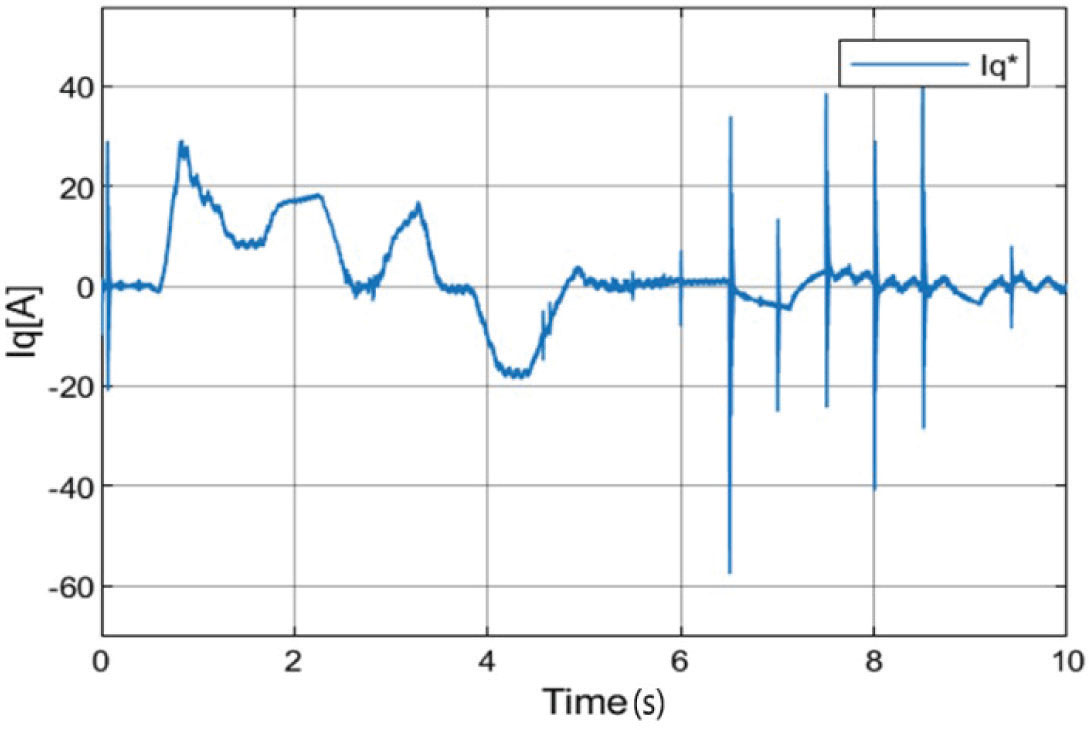
Figure 9.
Current control command showing very little chattering using the proposed the SOGI-HOSM. SOGI-HOSM, second-order generalised integrator-higher-order sliding mode.
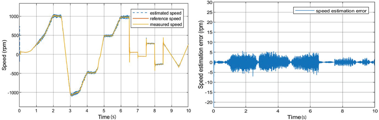
Figure 10.
Performance of the conventional STA at varying speeds. STA, super-twisting algorithm.
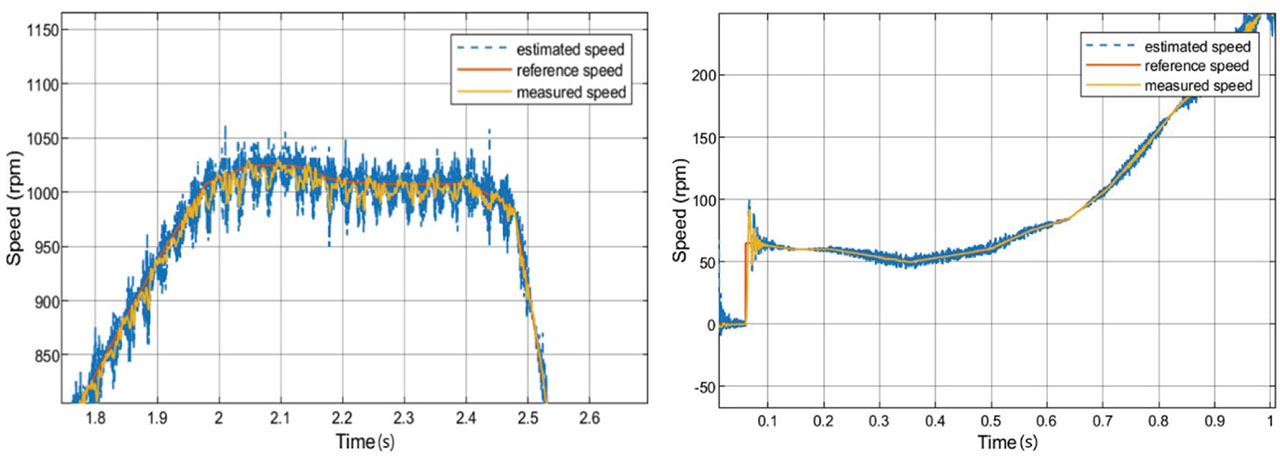
Figure 11.
A zoomed-in version of the performance of the conventional STA during frequency ramps (on the left) and at low speeds (on the right). STA, super-twisting algorithm.
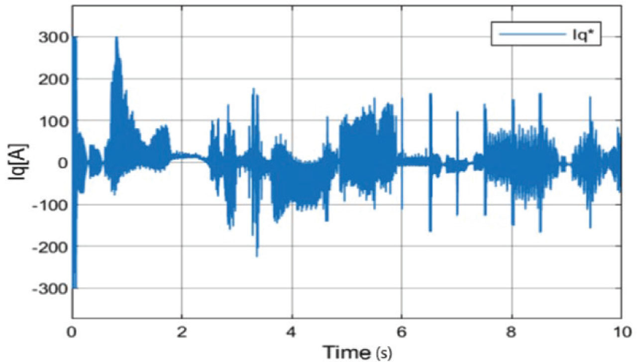
Figure 12.
Current control command showing very large chattering using the conventional STA. STA, super-twisting algorithm.
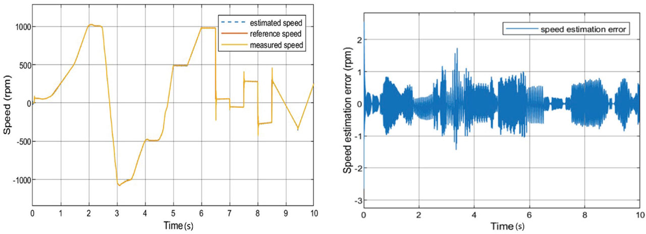
Figure 13.
Performance of the conventional SOGI-FLL at varying speeds. SOGI-FLL, second-order generalised integrator-frequency locked loop.
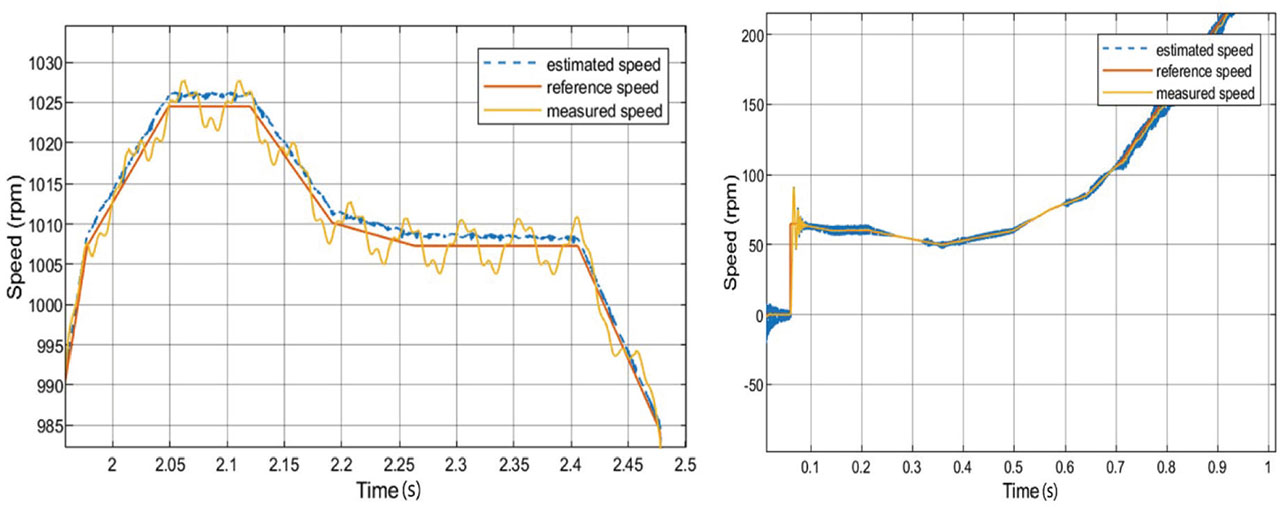
Figure 14.
A zoomed-in version of the performance of the conventional SOGI-FLL at during frequency ramps (on the left) and at low speeds (on the right). SOGI-FLL, second-order generalised integrator-frequency locked loop.
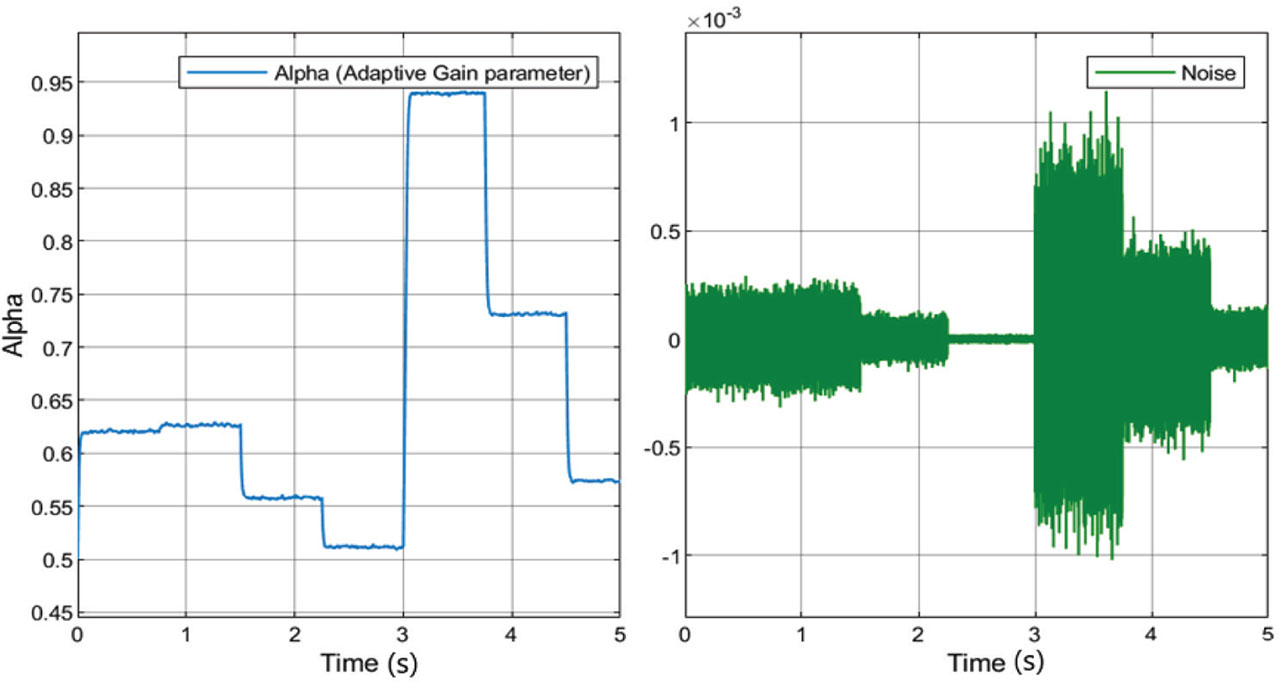
Figure 15.
Gain varying according to the noise level from the Butterworth filter.
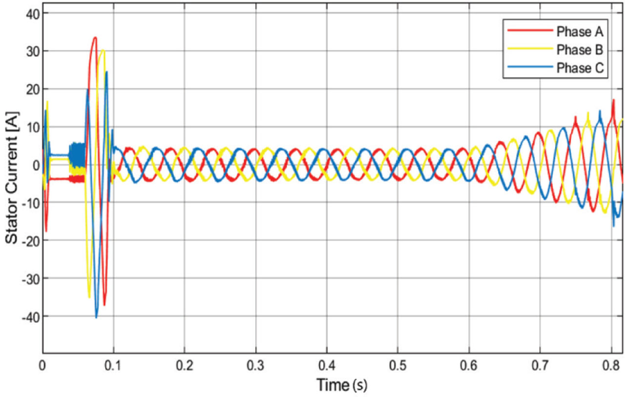
Figure 16.
Phase currents of induction machine showing abnormal high sensor noise addition.
Table 2.
Parameter variation and noise level.
| Parameter | Variation (%) | |
|---|---|---|
| ΔRs | Stator resistance variation | +18 |
| ΔLs | Stator inductance variation | +10 |
| ΔZn | Additional noise in current Sensor | ±5 |
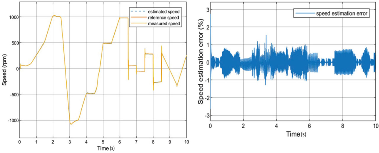
Figure 17.
Performance of the proposed SOGI-HOSM under parameter variation, additional sensor noise and under varying load torque. SOGI-HOSM, second-order generalised integrator-higher-order sliding mode.
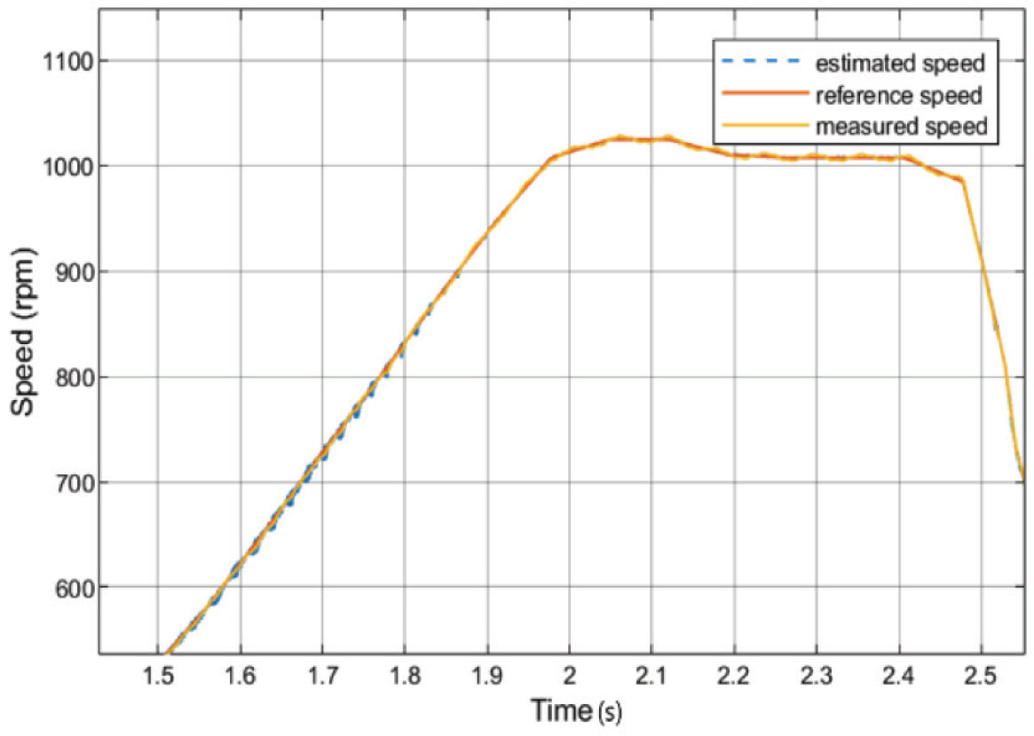
Figure 18.
A zoomed-in version of the performance of the proposed SOGI-HOSM under parameter variation, additional sensor noise and under varying load torque. SOGI-HOSM, second-order generalised integrator-higher-order sliding mode.
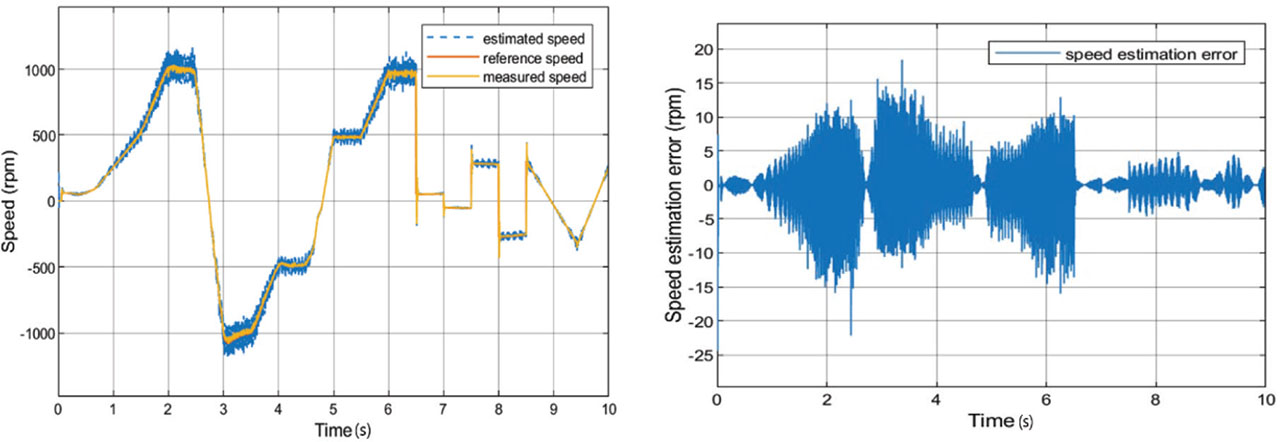
Figure 19.
Performance of the STA method under parameter variation, additional sensor noise and under varying load torque. STA, super twisting algorithm.
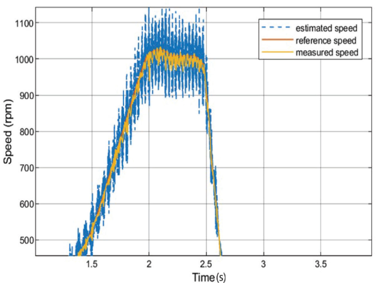
Figure 20.
A zoomed-in version of the performance of the conventional STA under parameter variation, additional sensor noise and under varying load torque. STA, super twisting algorithm.
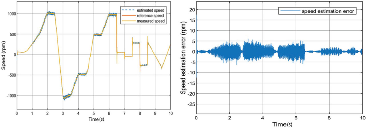
Figure 21.
Performance of the SOGI-FLL method under parameter variation, additional sensor noise and under varying load torque. SOGI-FLL, second-order generalised integrator-frequency locked loop.
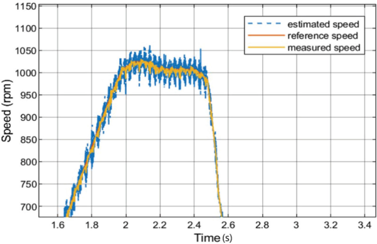
Figure 22.
A zoomed-in version of the performance of the SOGI-FLL method under parameter variation, additional sensor noise and under varying load torque. SOGI-FLL, second-order generalised integrator-frequency locked loop.