
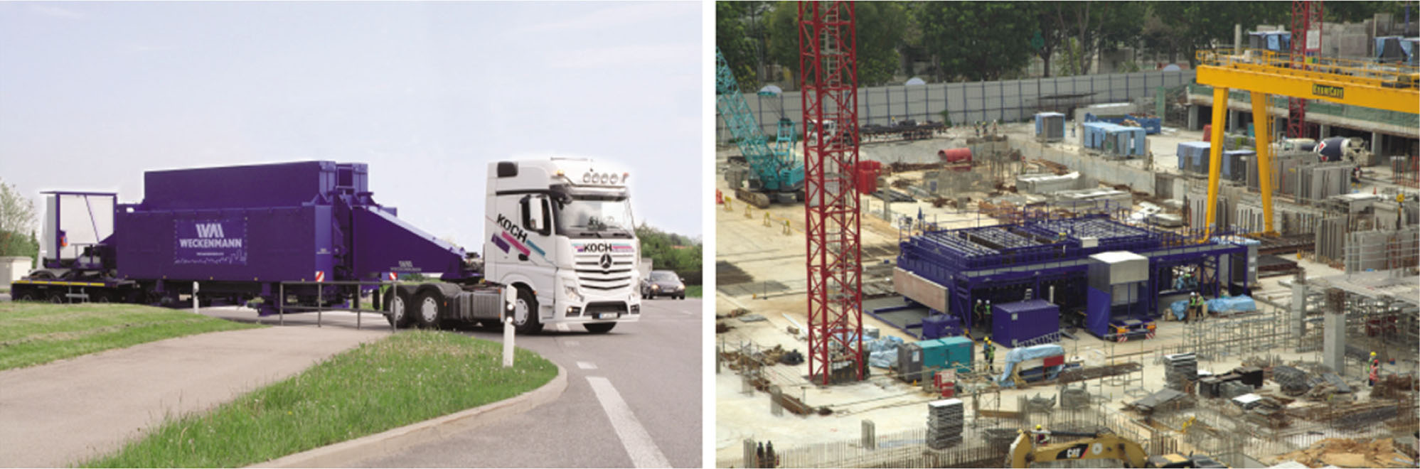
Fig. 1
Mobile Battery Mold in its closed (left) and open state (right) (Weckenmann, n.d.).
Tab. 1
Task times obtained from video analysis and corresponding range of possible values
| Task ID | Task Name | te [s] | max–min [%] | te max [s] | te min [s] |
|---|---|---|---|---|---|
| 1 | Place first MgO board (1) | 15 | 15 | 17.25 | 12.75 |
| 2 | Place second MgO board (1) | 30 | 15 | 34.5 | 25.5 |
| 3 | Place first MgO board (2) | 15 | 15 | 17.25 | 12.75 |
| 4 | Place second MgO board (2) | 30 | 15 | 34.5 | 25.5 |
| 5 | Place insulation material (1) | 20 | 15 | 23 | 17 |
| 6 | Place insulation material (2) | 20 | 15 | 23 | 17 |
| 7 | Spray glue on MgO board (1) | 20 | 0 | 20 | 20 |
| 8 | Spray glue on MgO board (2) | 20 | 0 | 20 | 20 |
| 9 | Spray glue on insulation material (1) | 20 | 0 | 20 | 20 |
| 10 | Spray glue on insulation material (2) | 20 | 0 | 20 | 20 |
| 11 | Compress (1) | 30 | 0 | 30 | 30 |
| 12 | Compress (2) | 30 | 0 | 30 | 30 |
| 13 | Prepare timber frame | 60 | 25 | 75 | 45 |
| 14 | Add timber frame | 30 | 25 | 37.5 | 22.5 |
| TOTAL | 360 | 402 | 318 |
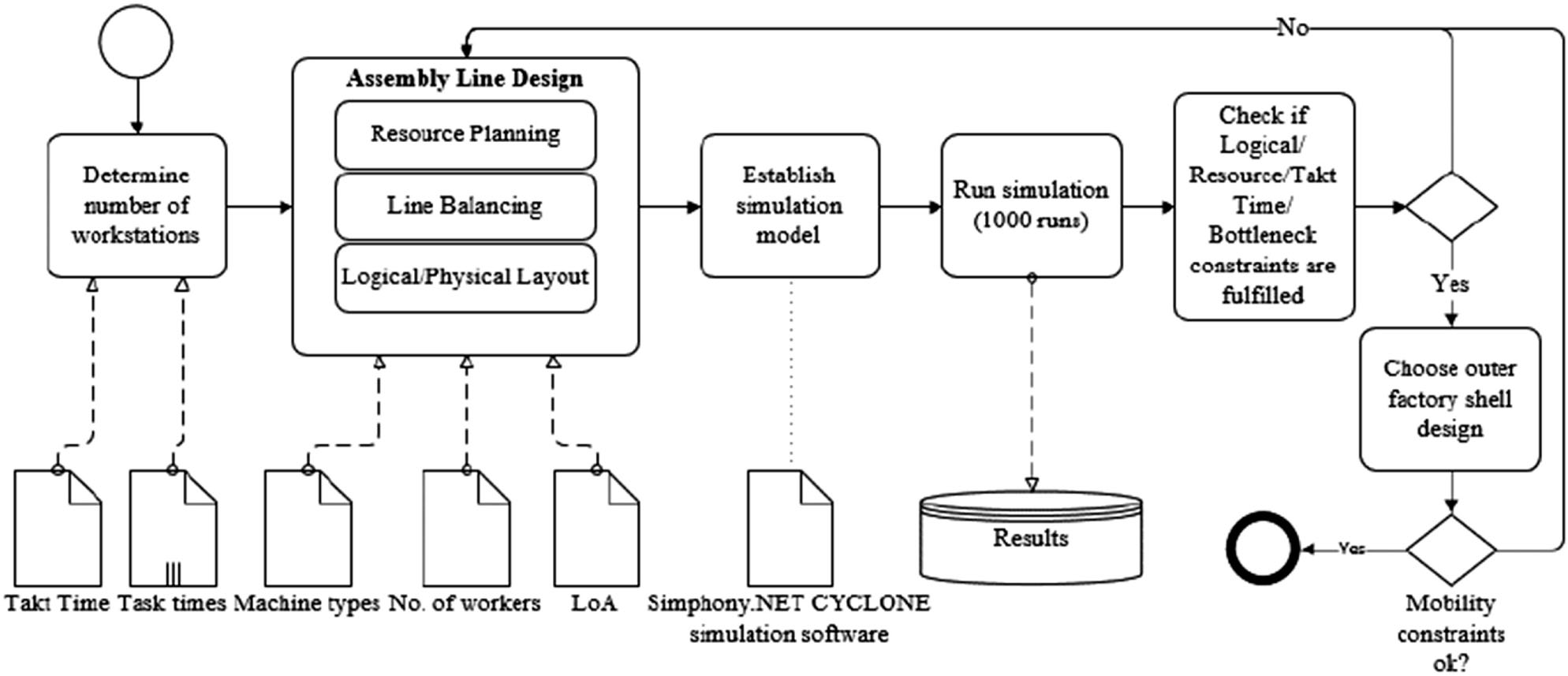
Fig. 2
Process map showing the implementation of CYCLONE into the ALD.
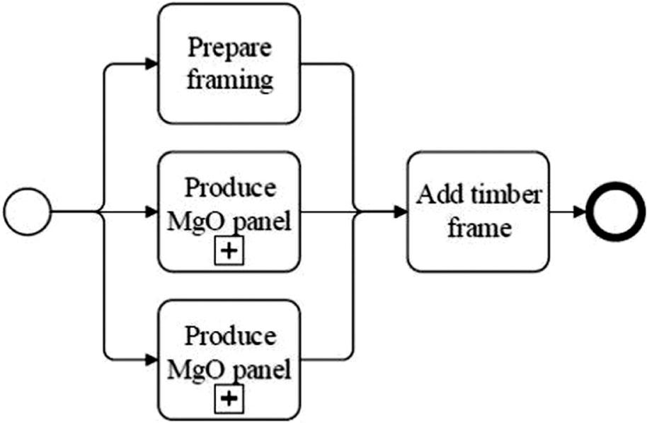
Fig. 3
General logical layout for a MgO SIP panel.

Fig. 4
Expanded “produce MgO panel” process.
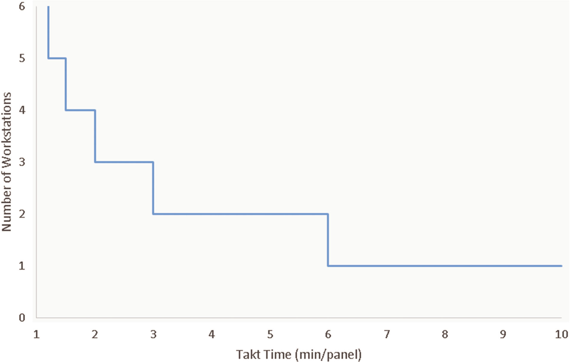
Fig. 5
Required number of workstations depending on customer takt time.
Tab. 2
Information related to each assembly line (AL) used for simulation
| AL-1 | AL-2.1 | AL-2.2 | AL-3.1 | AL-3.2 | |
|---|---|---|---|---|---|
| Distribution of tasks for each workstation (WS) (see Table 1 for Task IDs) | 1 WS 1: all | 2 WS 1: 1–12 WS 2: 13,14 | 2 WS 1: 1–10 WS 2: 11–14 | 3 WS 1: 1,3,5–10 WS 2: 2,4,11–12 WS 3: 13,14 | 3 WS 1: 1,2,5,7,9,11 WS 2: 3,4,6,8,10,12 WS 3: 13,14 |
| Capital cost (USD) | 10.700 | 10.700 | 10.700 | 11.500 | 19.400 |
| Labor cost (USD/hr) | 100 | 200 | 200 | 300 | 300 |
| Workers | 2 | 4 | 4 | 6 | 6 |
| Avg. cycle time (s) | 368 | 281 | 210 | 187 | 141 |
| Space required (mounted state*) (m2) | 91.6 | 91.6 | 91.6 | 107.6 | 107.6 |
| Space req. (unmounted state) (m2) | 27.1 | 27.1 | 27.1 | 32.0 | 43.7 |
| Total weight (tons) | 2.0 | 2.0 | 2.0 | 2,2 | 3.4 |
| Total WS utilization | 100% | 66.6% | 89.5% | 80.7% | 88.7% |
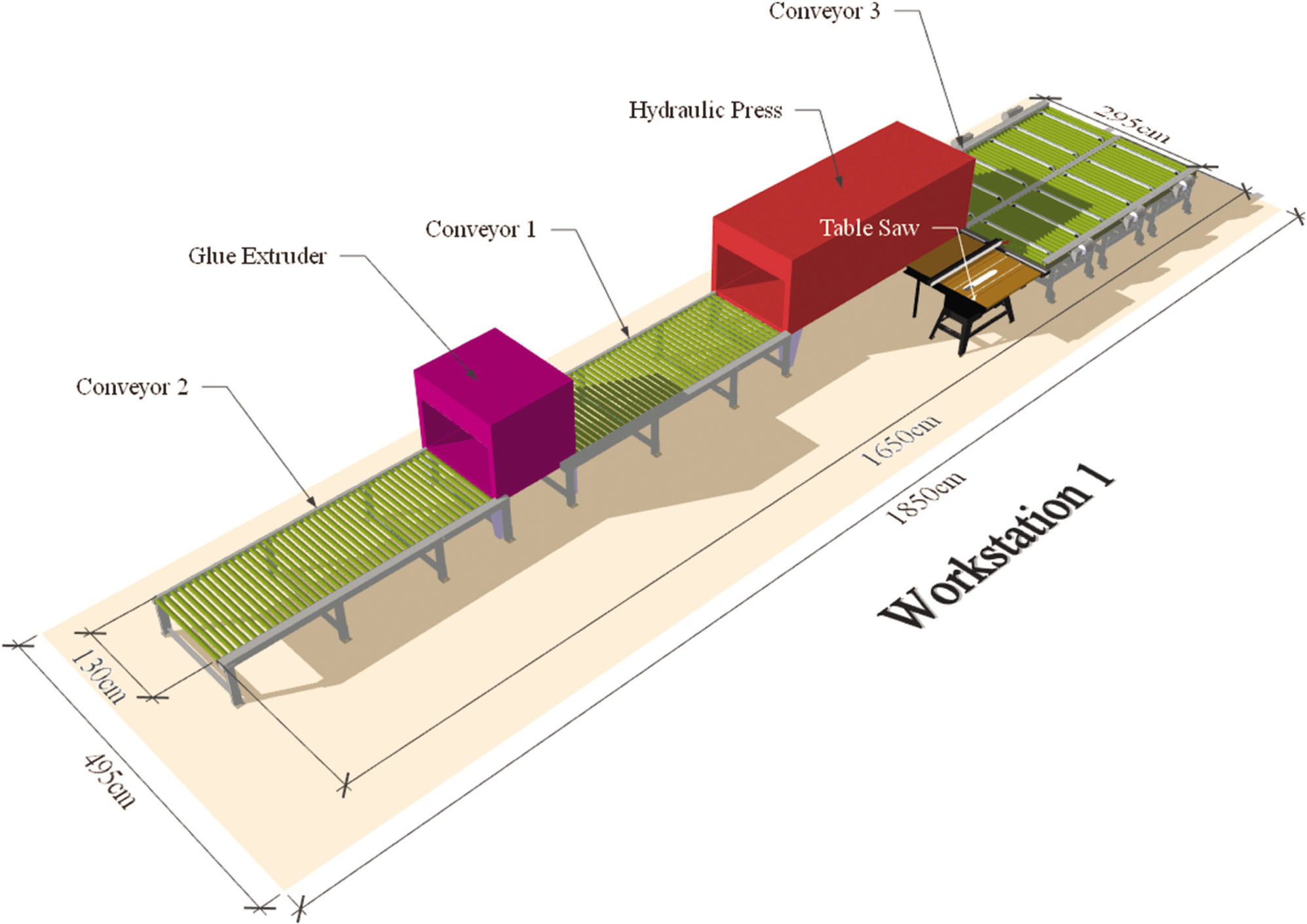
Fig. 6
3D model of AL-1 consisting of a single assembly line with a low-mid level of automation.