
Fig. 1.
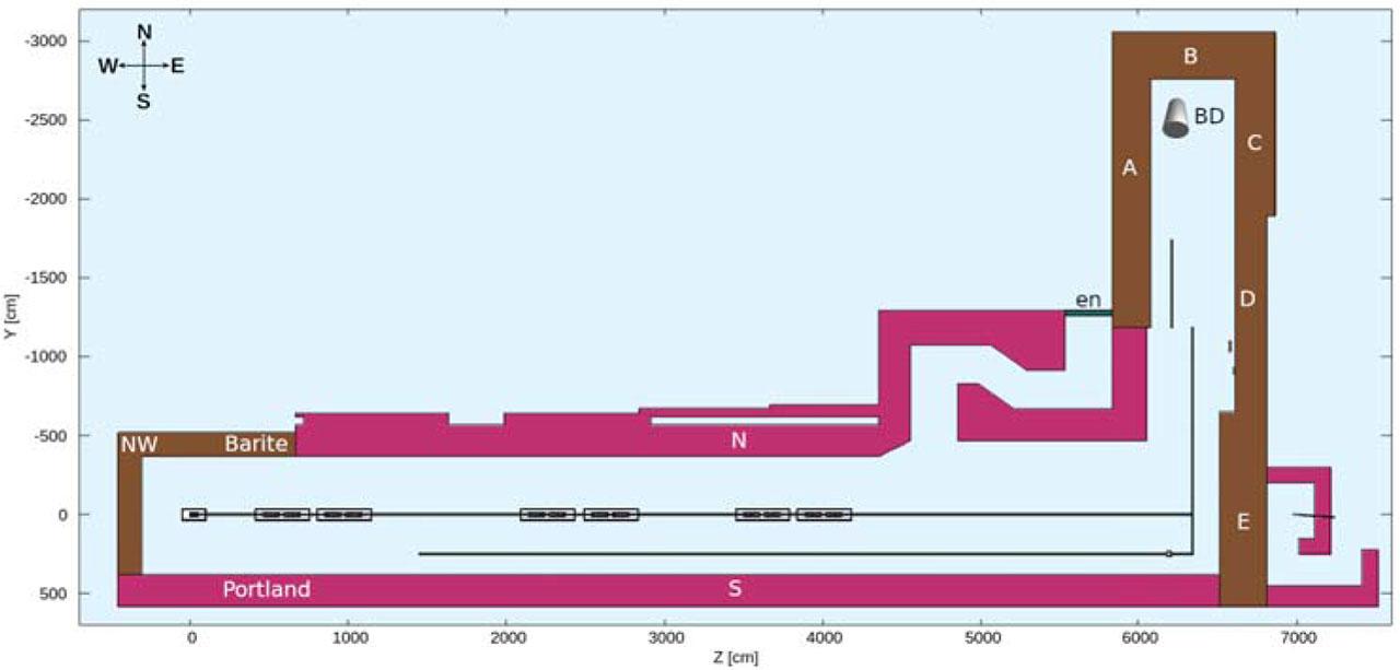
Fig. 2.
Fig. 3.
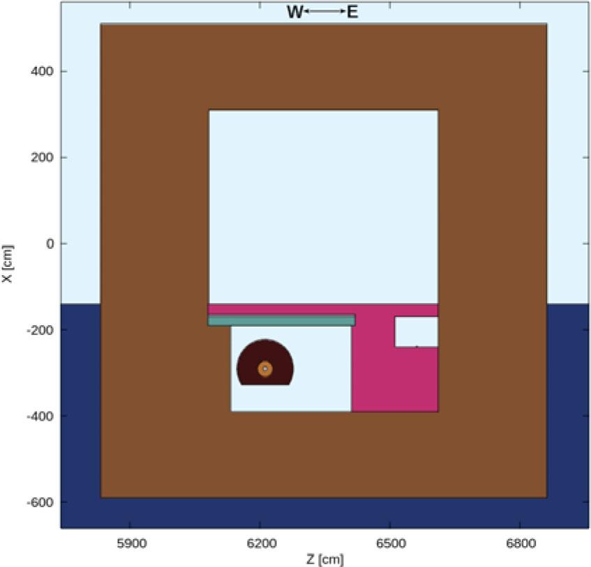
Fig. 4.
Fig. 5.
Fig. 6.
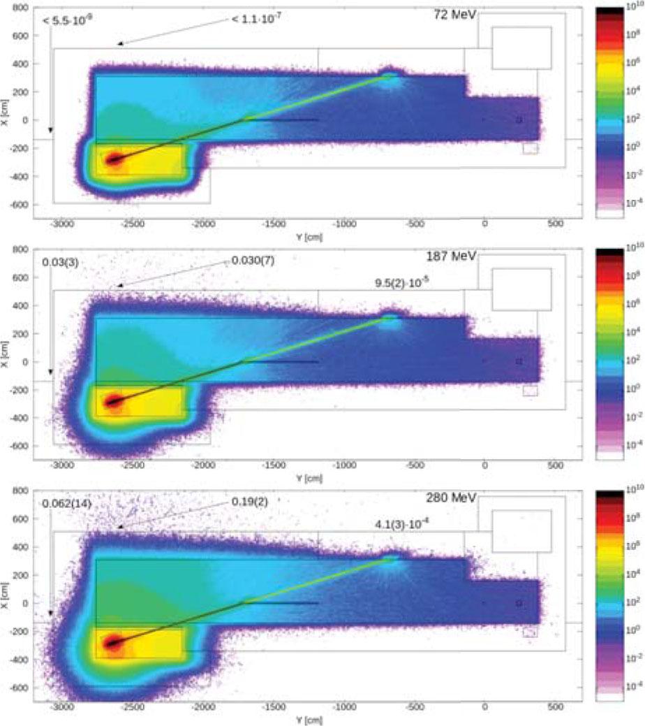
Fig. 7.
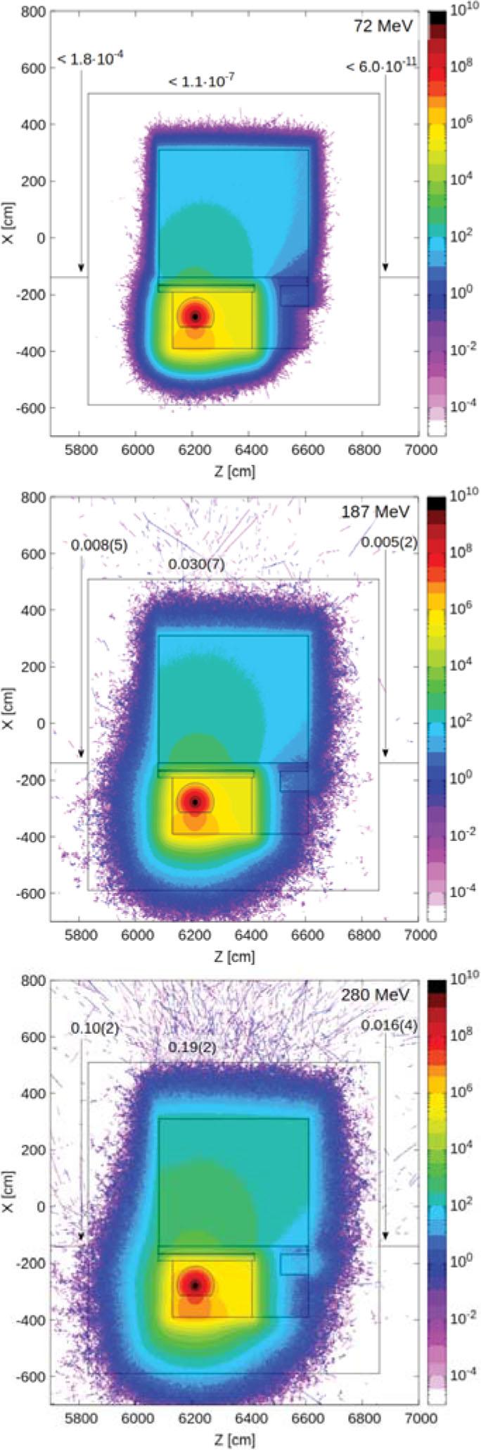
Fig. 8.
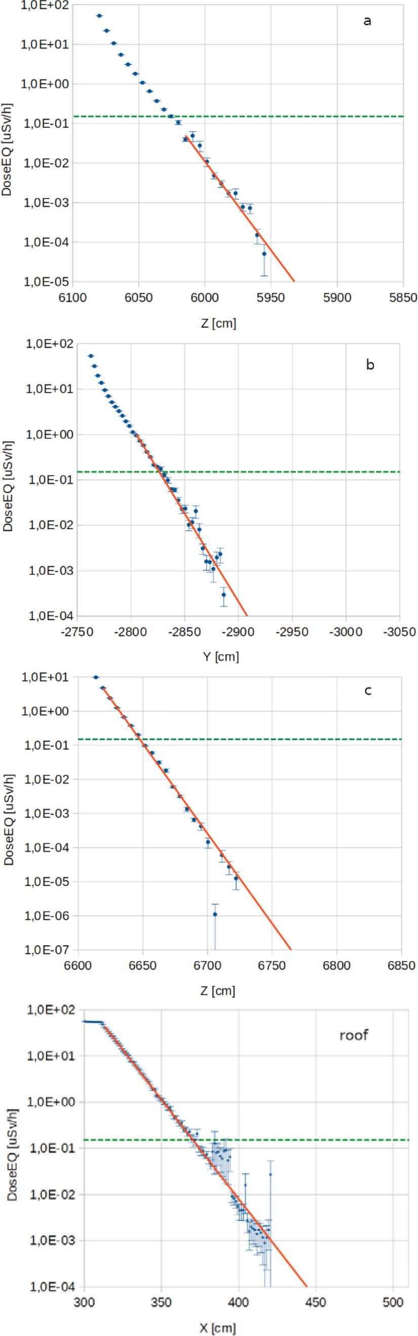
Fig. 9.
Fig. 10.
Density and chemical composition of materials used for calculations_ Chemical composition in terms of weight
| Density (g/cm3) | Portland concrete | Barite concrete | SS316LN | Soil |
|---|---|---|---|---|
| 2.3 | 3.2 | 7.8 | 2.7 | |
| H (Z = 1) | 2.2% | 0.4% | – | – |
| C (Z = 6) | 0.3% | – | 0.03% | |
| O (Z = 8) | 57.1% | 31.2% | – | 47% |
| Na (Z = 11) | 1.5% | – | – | 3% |
| Mg (Z = 12) | 0.1% | 0.1% | – | 2% |
| Al (Z = 13) | 2.1% | 0.4% | – | 8% |
| Si (Z = 14) | 30.6% | 1.0% | 1.00% | 28% |
| P (Z = 15) | – | – | 0.05% | – |
| S (Z = 16) | – | 10.8% | 0.03% | – |
| K (Z = 19) | 1.1% | – | – | 3% |
| Ca (Z = 20) | 4.3% | 5.0% | – | 4% |
| Cr (Z = 24) | – | – | 18.50% | – |
| Mn (Z = 25) | – | – | 2.00% | – |
| Fe (Z = 26) | 0.7% | 4.8% | 67.14% | 5% |
| Ni (Z = 28) | – | – | 11.25% | – |
| Ba (Z = 56) | – | 46.3% | ||
Summary of the radiation leaks outside the bunker branch walls calculated directly for 187 MeV and 280 MeV and estimated on the basis of the dose rate attenuation in the branch walls shown in Fig_ 8 for 72 MeV_ Radiation leakages through walls D and E are so small that it has not been possible to estimate their magnitude
| Place | 72 MeV | 187 MeV | 280 MeV |
|---|---|---|---|
| Total dose rate (μSv/h) | |||
| A | <1.8 × 10⁻⁴ | 0.008(5) | 0.10(2) |
| B | <5.5 × 10⁻⁹ | 0.030(3) | 0.062(14) |
| C | <6.0 × 10⁻¹¹ | 0.005(2) | 0.016(4) |
| D and E | – | 0.005(2) | 0.019(6) |
| Roof | <1.1 × 10⁻⁷ | 0.030(7) | 0.19(2) |
Summary of the maximum soil activity averaged in 50 cm × 50 cm × 50 cm cubes directly below the dump room
| Cooling time | 72 MeV | 187 MeV | 280 MeV |
|---|---|---|---|
| Maximum activity from the beam (Bq/cm3) | |||
| 1 min | <8 × 10⁻⁶ | 3.37(15) × 10−3 | 2.98(9) × 10−2 |
| 1 h | <8 × 10⁻⁶ | 1.55(8) × 10−3 | 1.36(5) × 10−2 |
| 1 day | <8 × 10⁻⁷ | 5.3(3) × 10−4 | 4.7(2) × 10−3 |
| 1 week | <8 × 10⁻⁷ | 9.6(19) × 10−5 | 8.5(12) × 10−4 |
| 30 days | <8 × 10⁻⁷ | 6.9(13) × 10−5 | 6.0(8) × 10−4 |
| 1 year | <2 × 10⁻⁷ | 1.1(2) × 10−5 | 9.9(9) × 10−5 |