

Fig. 1.
The ESS linac schema with DmpL and A2T GB locations (based on Fig. 1 from Ref. [2]).
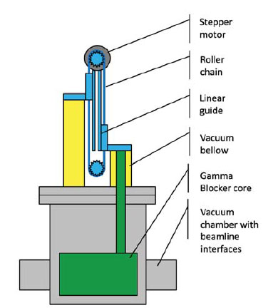
Fig. 2.
Block model of GB system including the most important elements.
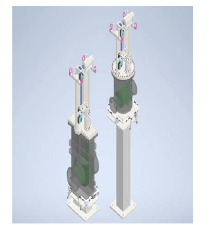
Fig. 3.
Detailed 3D models of both GBs (DmpL – left, A2T – right).
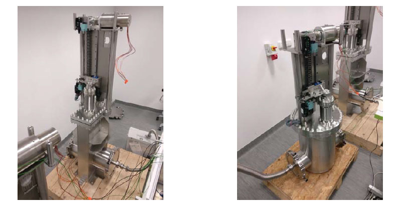
Fig. 4.
GBs during factory test (DmpL – left, A2T – right).