Have a personal or library account? Click to login
Preliminary computational and experimental design studies of the ISHTAR thermostatic rig for the high-temperature reactors materials irradiation Cover

Preliminary computational and experimental design studies of the ISHTAR thermostatic rig for the high-temperature reactors materials irradiation

Open Access
|Nov 2021

Figures & Tables

Fig. 1

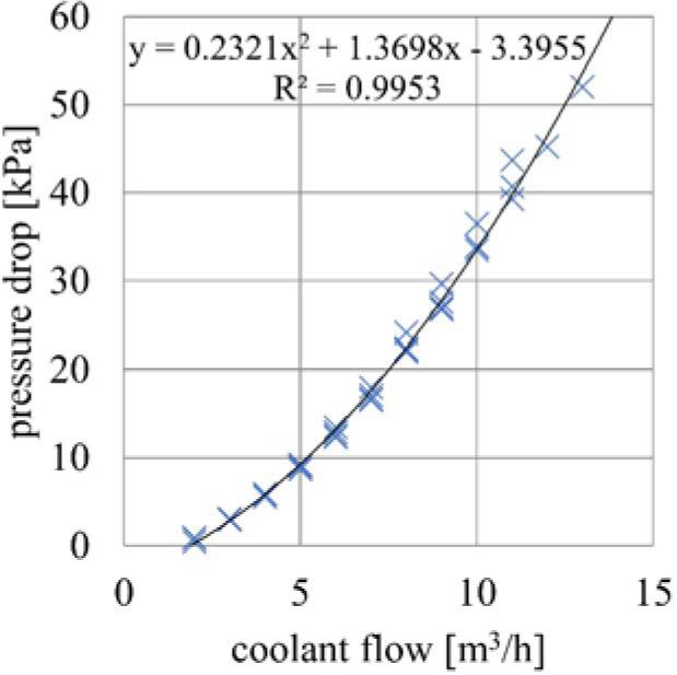
Results of the pressure drop vs. coolant flow measurement in the mockup of the irradiation channel.

Fig. 2

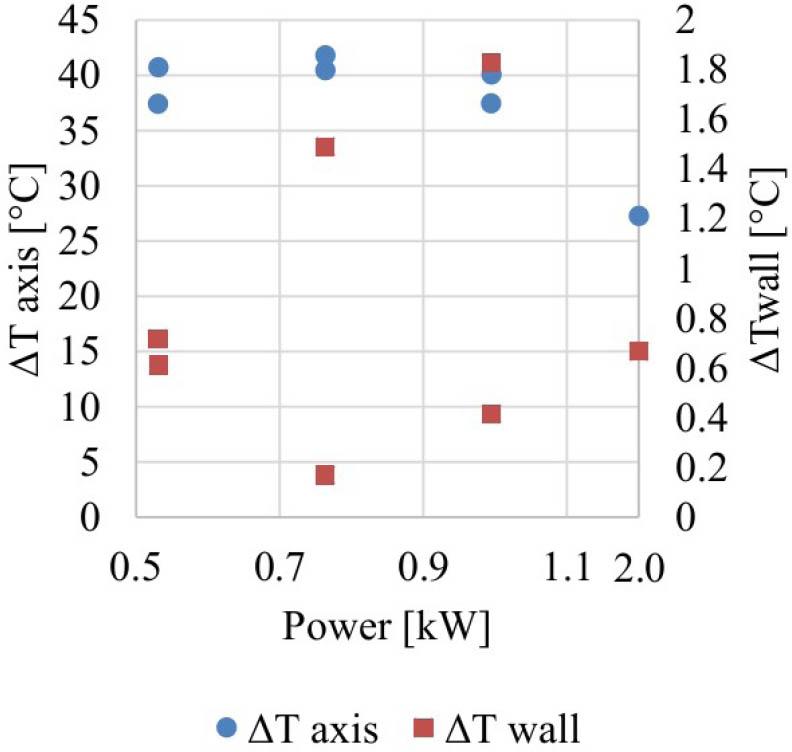
One-dimensional code validation. Measured to computed temperature differences as a function of the rig power. Note that the last point on the horizontal axis is out of the scale.

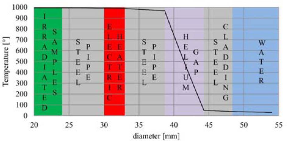
Fig. 3

Result of the 1D heat transfer calculation of the ISHTAR rig. The dimensions of the layers in the radial direction are marked approximately.

Fig. 4

Graphite specimen assembly with thermocouples attached.

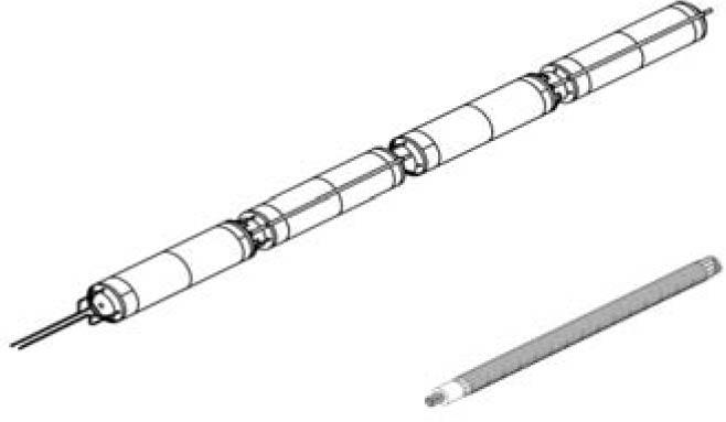
Fig. 5

Top: Isometric view of the instrumented material sample containers. Bottom: Isometric view of the electrical heater coils.

Fig. 6

ISHTAR thermostatic rig overview.

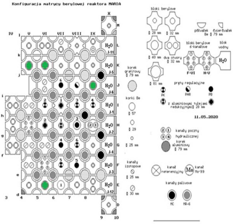
Fig. 7

Allotted irradiation locations for the ISHTAR irradiation rig in MARIA reactor core marked in green. The scheme covers the core without the reflector blocks. The fuel elements are marked with dark gray circles, e.g., j-5.

Fig. 8

Geometrical model. 1 – inner shell, 2 – electrical heater, 3 – samples with holder, 4 – outer shell, 5 – “crown”.

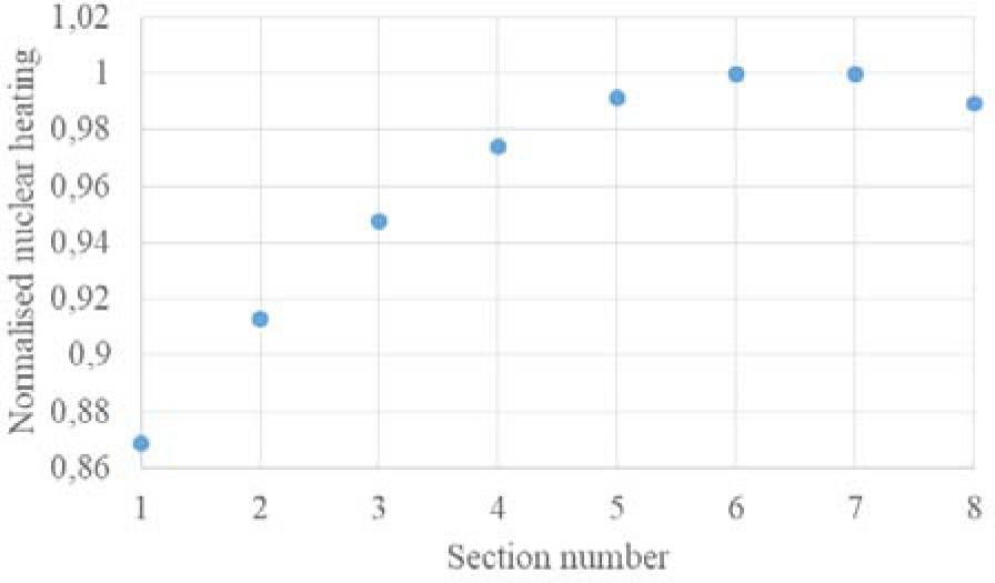
Fig. 9

Normalized nuclear heating applied to the model.

Fig. 10

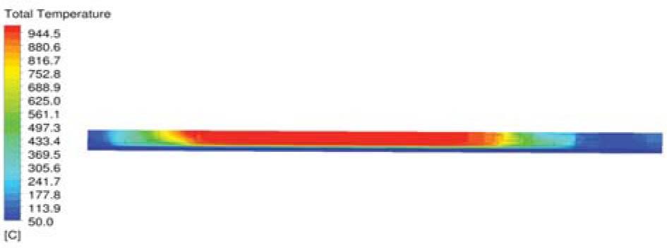
Temperature field in the core part of the irradiation rig.

Natural convection parameters [12]

Gr·Pr<103103–106106–1010
C10.1050.4
N00.30.2
DOI: https://doi.org/10.2478/nuka-2021-0019 | Journal eISSN: 1508-5791 | Journal ISSN: 0029-5922
Language: English
Page range: 127 - 132
Submitted on: Jan 4, 2021
Accepted on: Feb 7, 2021
Published on: Nov 25, 2021
Published by: Institute of Nuclear Chemistry and Technology
In partnership with: Paradigm Publishing Services
Publication frequency: 4 issues per year

© 2021 Anna Talarowska, Maciej Lipka, Grzegorz Wojtania, published by Institute of Nuclear Chemistry and Technology
This work is licensed under the Creative Commons Attribution-NonCommercial-NoDerivatives 4.0 License.