
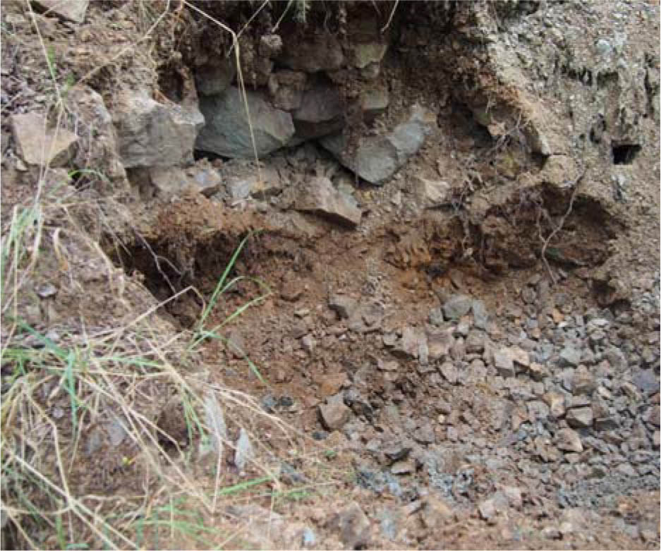
Fig. 1
The photo of a material sampling point at the post-mining uranium dump in Radoniów.
Table 1
Chemical analysis of samples taken from the Small Dump in Radoniów
| U | Th | Cu | Co | Mn | Zn | La (ppm) | V | Yb | Mo | Ni | Sb | Fe |
|---|---|---|---|---|---|---|---|---|---|---|---|---|
| 747 | 12 | 12 | 21 | 291 | 58 | 24 | 47 | 3 | 3 | 27 | 5 | 23 200 |
| 801 | 14 | 14 | 18 | 369 | 100 | 29 | 52 | 3 | 5 | 23 | 7 | 25 200 |
Table 2
The composition of K0 bacteria medium used in the bioleaching process
| Component | Concentration (g/dm3) |
|---|---|
| (NH4)2SO4 | 5 |
| KCl | 0.166 |
| KH2PO4 | 0.083 |
| MgSO4 · 7H2O | 0.830 |
| Ca(NO3)3 | 0.024 |
| pH 2 | |
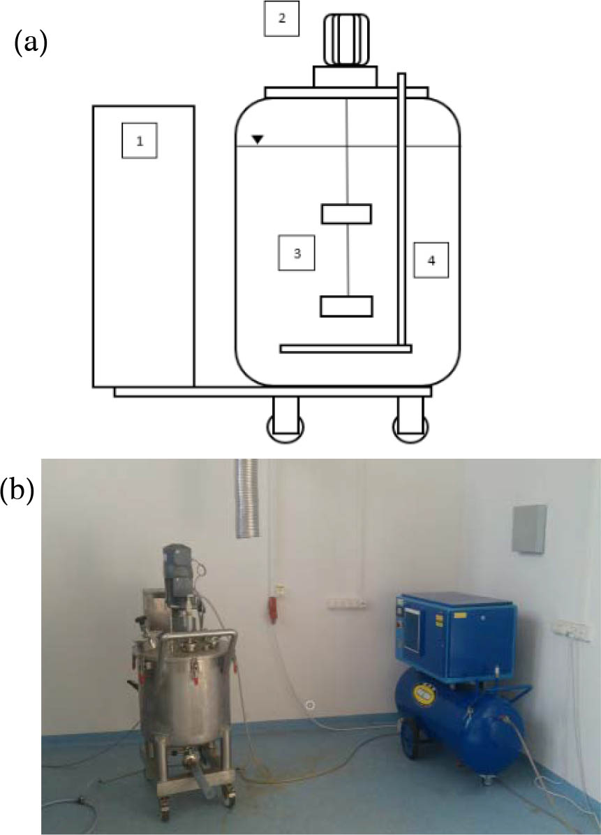
Fig. 2
(a) The scheme of the reactor: 1 – double-Rushton mixer, 2 – bubbler, 3 – control cabinet, and 4 – engine; (b) the reactor and control system panel built by Kates sp. z o. o.
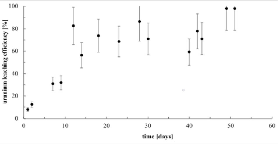
Fig. 3
The efficiency of uranium bioleaching in the reactor (initial uranium concentration in the rock: 750–800 ppm).
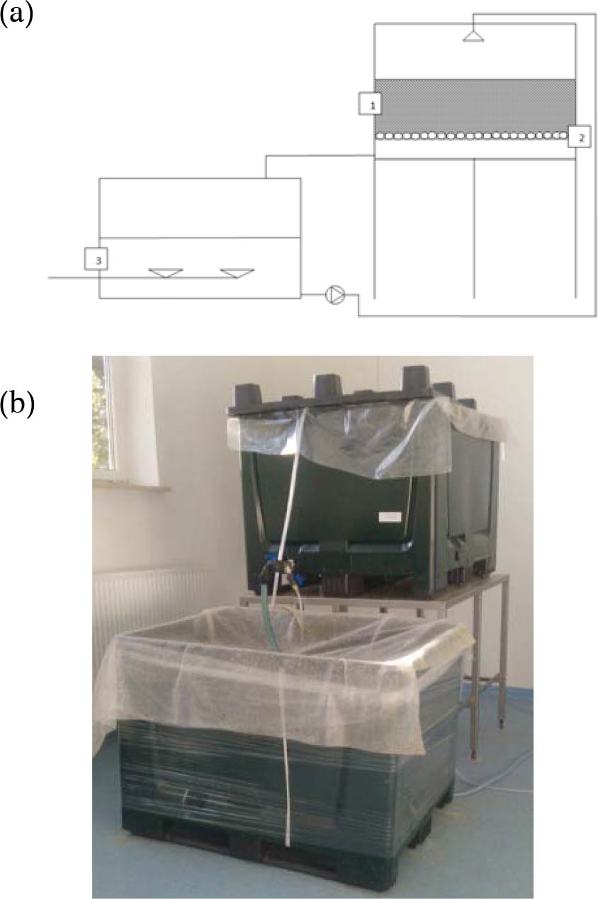
Fig. 4
Fixed-bed reactor. (a) The scheme of the experimental stand: 1 – leaching solution, 2 – U-bearing rocks from Radoniów pile, and 3 – post-leaching solution. (b) The experimental rig photo.
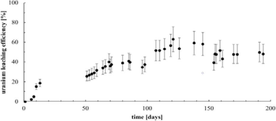
Fig. 5
The effect of time on uranium bioleaching in fixed-bed deposit (initial uranium concentration in the rock: 750–800 ppm).
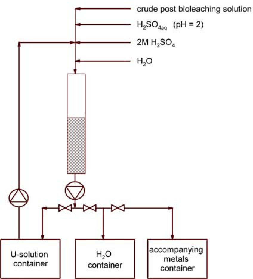
Fig. 6
The scheme of ion exchange process, used for the purification uranium post-bioleaching solution.
Table 3
The degree of uranium concentration by IX chromatography in the sample after bioleaching
| Sample | Cycle no. | U (ppm) | Uranium concentration degree |
|---|---|---|---|
| U-1 | I | 272 | – |
| U-2 | X | 327 | 1.20 |
| U-3 | XIV | 375 | 1.38 |
| U-4 | XVIII | 413 | 1.52 |
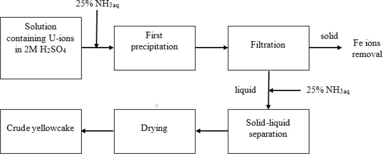
Fig. 7
Two-step precipitation of ammonium diuranate from prior purified post-bioleaching solution.