
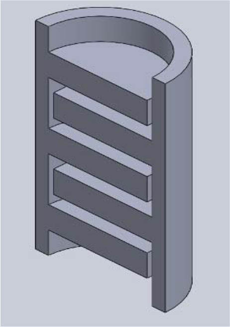
Fig. 1
Section of the distillation column that was designed using SolidWorks™.
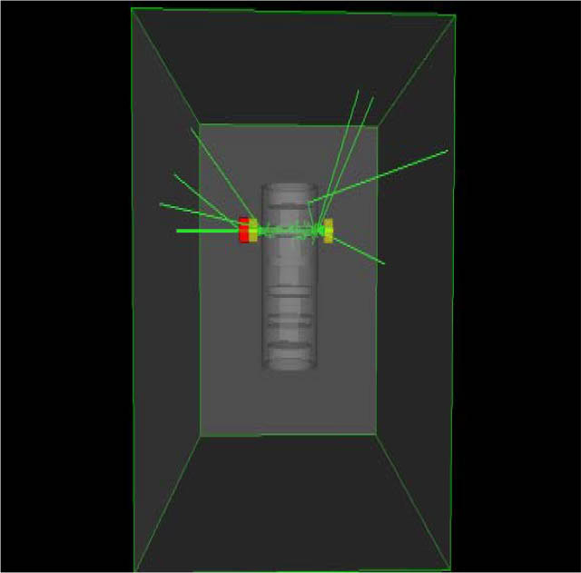
Fig. 2
The simulation setup of the column scan.
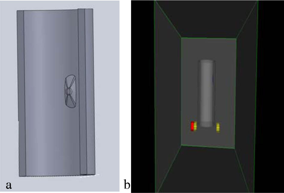
Fig. 3
(a) SolidWorks™ design of the pipe with solid deposit. (b) Simulation setup.
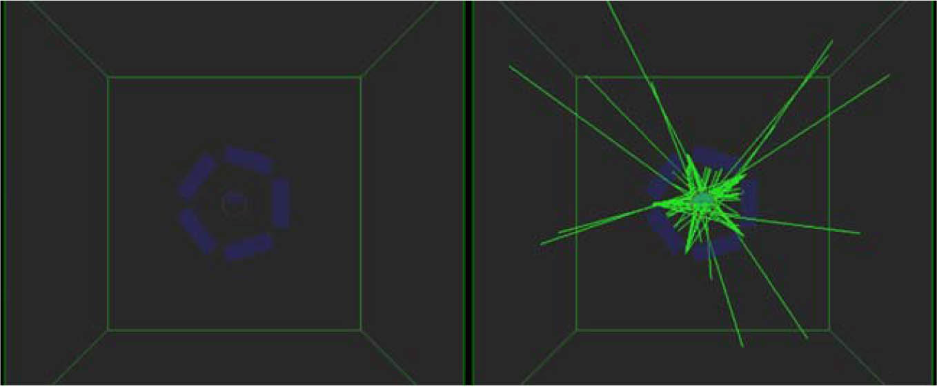
Fig. 4
Simulation setup for the fifth-generation CT scan.
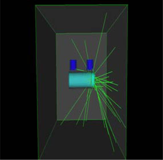
Fig. 5
The simulation setup used for flow rate measurement using a radiotracer.
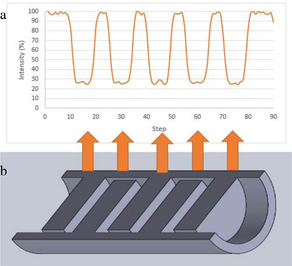
Fig. 6
(a) Simulation results of the gamma ray scanning of a distillation column. (b) A section of a distillation column; the arrows indicate the corresponding intensity measured after radiation has passed through the trays.
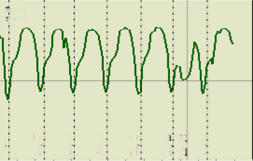
Fig. 7
Experimental gamma scanning profile (reproduced from [26]).
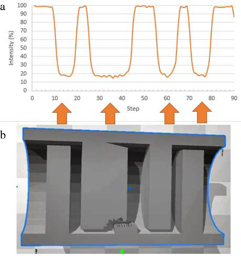
Fig. 8
(a) Simulation results of the gamma ray scanning of a distillation column with a collapsed tray. (b) A section of a distillation column with a collapsed tray.
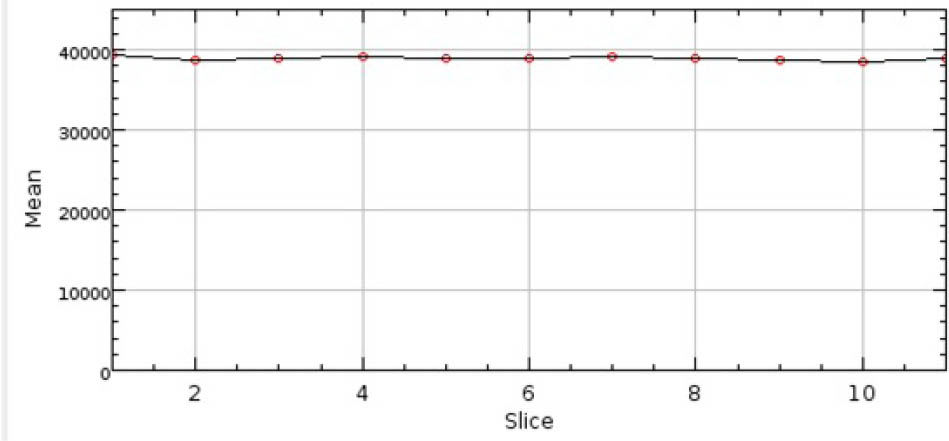
Fig. 9
Simulation results of gamma scanning of a deposit-free pipe.
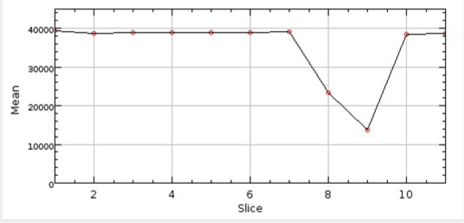
Fig. 10
Simulation results of a pipe with deposited solid phase.
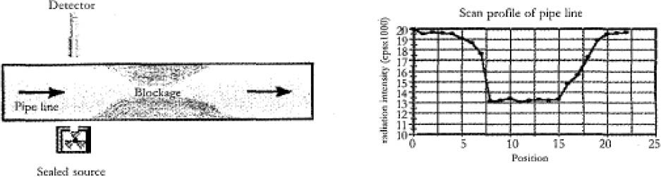
Fig. 11
Application of gamma scanning to detect blockage in pipes (reproduced from [27]).
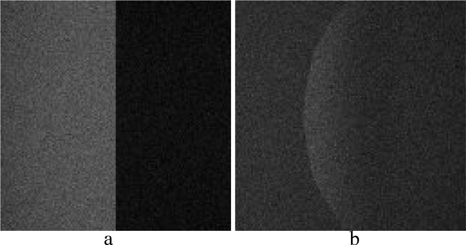
Fig. 12
The five projections of CT of the pipe.
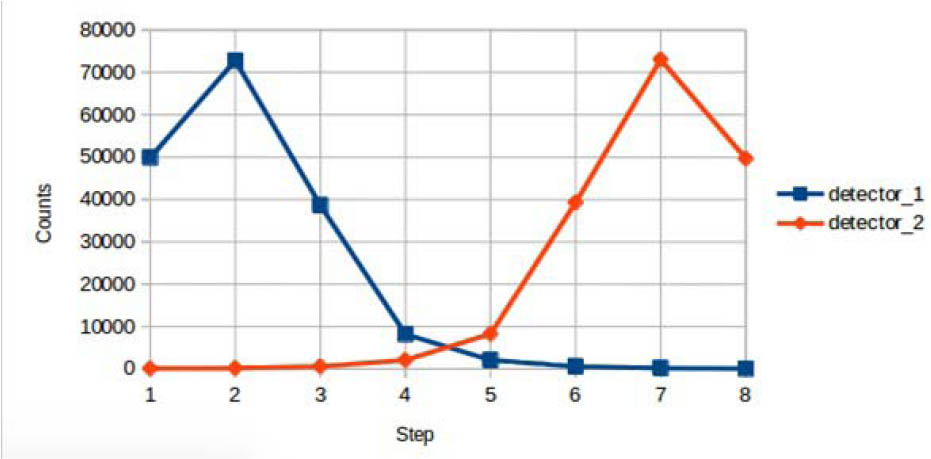
Fig. 13
Simulation result of the flow rate measurement.