
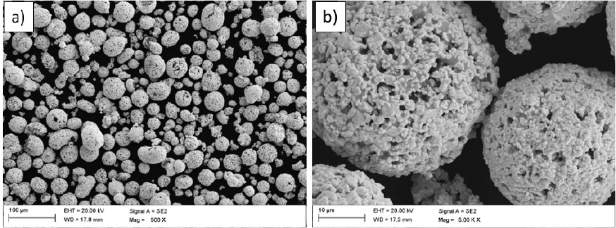
Fig. 1.
Morphology of the initial feedstock powder: (a) standard view, (b) detailed view
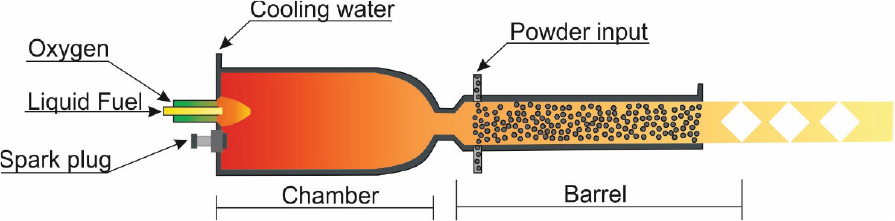
Fig. 2.
Scheme of the HVOF deposition method
Table 1.
HVOF process parameters and sample code
| Sample | Medium feed rate | Spray distance mm | |||
|---|---|---|---|---|---|
| Kerosene l/min | Oxygen l/min | Nitrogen l/min | Powder g/min | ||
| SBS1 | 0.380 | 950 | 12 | 70 | 300 |
| MBS2 | 0.435 | 900 | 360 | ||
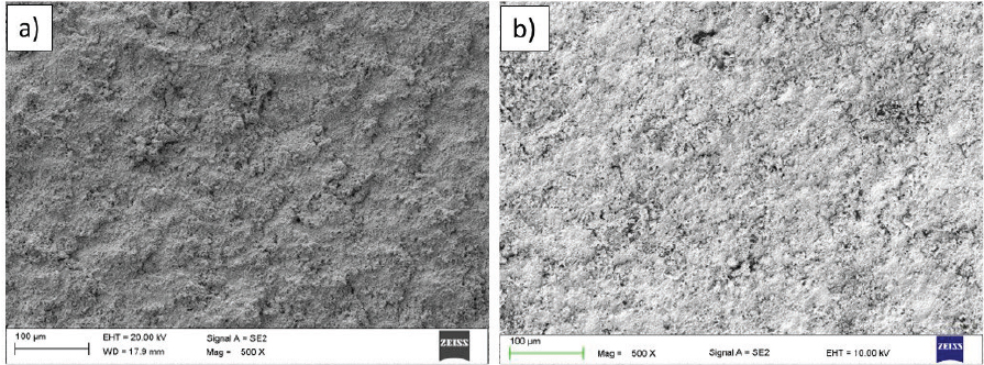
Fig. 3.
The surface topography of sprayed coatings: (a) MBS, (b) SBS
Table 2.
Results for surface roughness of the as-sprayed coatings
| Sample | Ra | Rp | Rv | Rz |
|---|---|---|---|---|
| SBS | 3.36 ± 0.23 | 10.20 ± 2.14 | 7.95 ± 1.48 | 18.10 ± 3.15 |
| MBS | 4.28 ± 0.24 | 11.84 ± 2.47 | 9.92 ± 1.83 | 21.77 ± 3.51 |
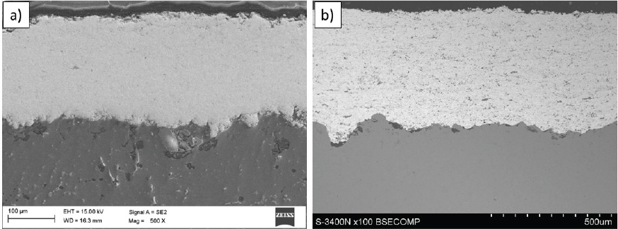
Fig. 4.
The SEM images of the coatings’ cross-sections at low magnification (500x): (a) MBS and (b) SBS
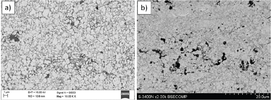
Fig. 5.
The SEM images of the coatings’ cross-sections at high magnification (10,000x): (a) MBS and (b) SBS
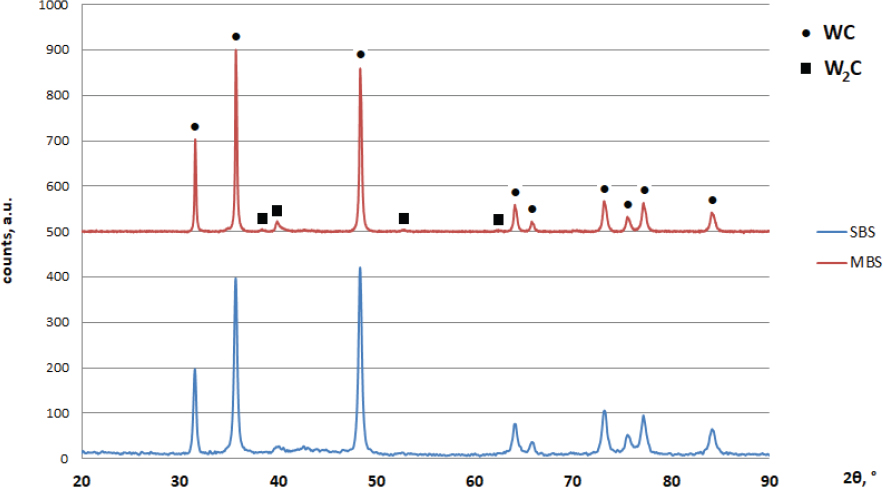
Fig. 6.
XRD patterns for HVOF-sprayed coatings
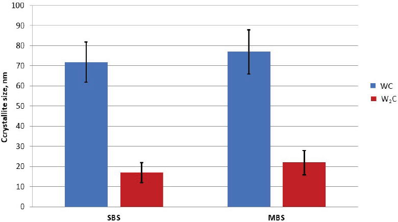
Fig. 7.
Results of crystallite size calculations for WC and W2C phases in the sprayed coatings