
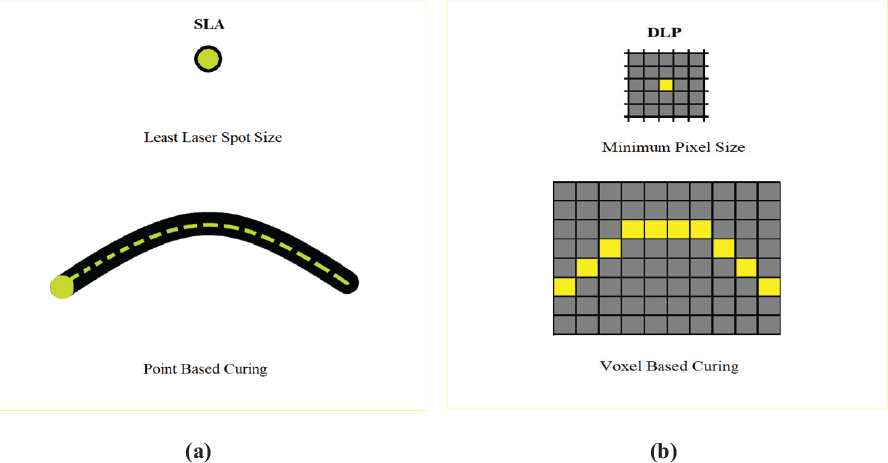
Fig. 1.
Depiction of printing (a) SLA: point-based approach; (b) DLP: area scanning
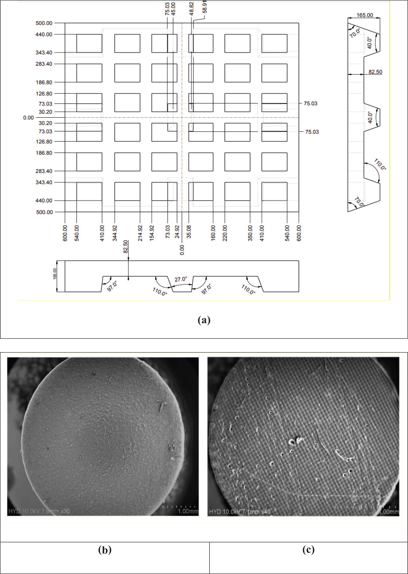
Fig. 2.
Surface morphology depiction of 1-mm printed parts at 1-mm tolerance resolution using (a) CAD geometry (b) DLP (c) SLA
Table 1.
Process parameters corresponding to SLA 3D printing of pallet coupons
| Layer Thickness (μm) | Material |
|---|---|
| 25 | Gray V4 |
| 50 | Model V3 |
| 100 | Clear V4 |
Table 2.
Material properties of the industry grade pallet 3D printing materials—SLA
| Materials | Grey V4 | Model V2 | Clear V2 |
|---|---|---|---|
| Tensile strength (MPa) | 65 | 42 | 65 |
| Percentage of elongation | 6.2 | 4.8 | 6.2 |
| Izod notched impact (J/m) | 25 | 24 | 25 |
| Heat deflection temperature (°C) | 73.1 | 75 | 73.1 |
Table 3.
Orthogonal L9 array experimental runs for SLA 3D printing of pallet coupons
| Experimental runs | Layer thickness | Material |
|---|---|---|
| 1 | 25 | Gray V4 |
| 2 | 25 | Clear v4 |
| 3 | 25 | Model V2 |
| 4 | 50 | Gray V4 |
| 5 | 50 | Clear |
| 6 | 50 | Model V2 |
| 7 | 100 | Gray V4 |
| 8 | 100 | Clear |
| 9 | 100 | Model V2 |
Table 4.
Process parameters corresponding to DLP 3D printing of pallet coupons
| Layer thickness (μm) | Material |
|---|---|
| 30 | FlexBlack-20 |
| 40 | ToughBlack-20 |
| 50 | ProBlack-10 |
Table 5.
Material properties of the industry grade pallet 3D printing materials—DLP
| Materials | Flex BLK-20 | Tough BLK-20 | Pro BLK-10 |
|---|---|---|---|
| Tensile strength (MPa) | 35 | 42 | 56 |
| Percentage of elongation | 71 | 27 | 12 |
| Izod notched impact (J/m) | 105 | 35 | 22 |
| Heat deflection temperature (°C) | 41 | 55 | 70 |
Table 6.
Orthogonal L9 array experimental runs for DLP 3D printing of pallet coupons
| Experimental runs | Layer thickness | Material |
|---|---|---|
| 1 | 30 | FlexBLK-20 |
| 2 | 30 | ToughBLK-20 |
| 3 | 30 | ProBLK-10 |
| 4 | 40 | ToughBLK-20 |
| 5 | 40 | ProBLK-10 |
| 6 | 40 | FlexBLK-20 |
| 7 | 50 | ProBLK-10 |
| 8 | 50 | FlexBLK-20 |
| 9 | 50 | ToughBLK-20 |
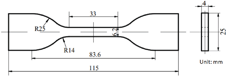
Fig. 3.
SLA and DLP 3D printing of tensile specimen dimensions: ASTM D638
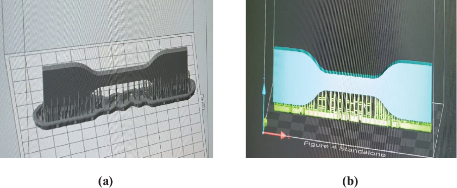
Fig. 4.
GUI type IV tensile specimen (a) Preform: SLA, (b) 3D sprint: DLP software
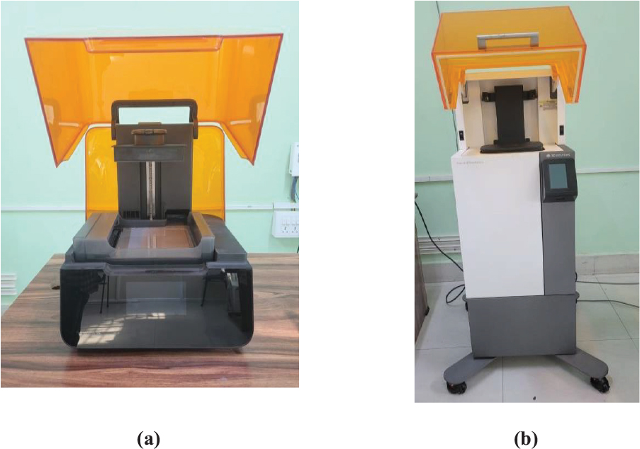
Fig. 5.
3D printing of coupons (a) SLA Form 3 (b) DLP Figure 4 Standalone (CITD additive lab facility, MSME Tool room facility, Hyderabad, Govt. of India)
Table 7.
3D printing machine details: SLA – Form 3 and DLP
| Machine Name | Form labs 3 | Machine Name | DLP Standalone System |
|---|---|---|---|
| Build | 145 × | Build | 124.8 × |
| Volume | 145 × 185 cc | Volume | 70.2 × 196 cc |
| Resolution | 25 μ | Resolution | 1920×1080 |
| Laser power | 250 mW | Wavelength | 405 nm |
| Laser Spot size | 85μ | Pixel pitch | 65μ |
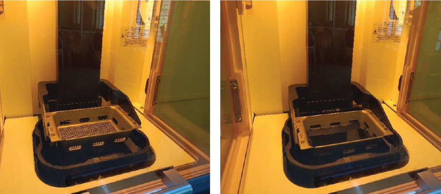
Fig. 6.
Bottom-up approach 3D printing of pallet coupons in DLP method
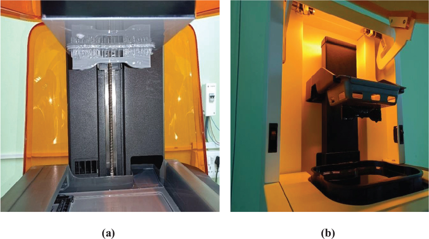
Fig. 7.
3D printed ASTM D638 type IV pallet coupon using (a) SLA process: form 3 printer (b) DLP method: stand-alone printer
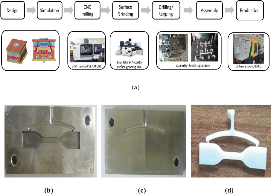
Fig. 8.
(a) Complete process for developing a commercial pallet tensile coupon replicator (CITD, Hyderabad facilities); (b) bottom half; (c) top half of injection mould die; (d) ABS pallet tensile specimen coupon prepared with gate and runner
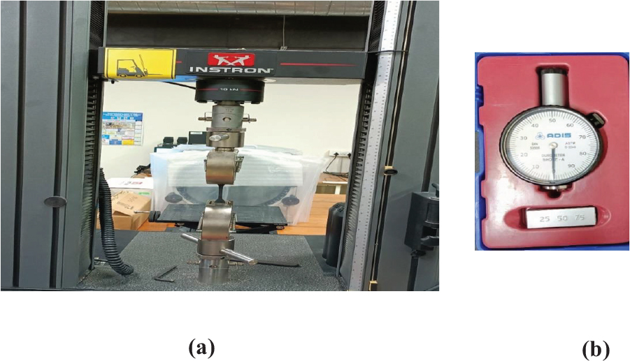
Fig. 9.
Investigation of (a) uniaxial tensile test of SLA and DLP 3D printed ASTM D638 type IV samples; machine used: Instron 5966 model, (b) Shore A hardness durometer
Table 8.
Response variables for SLA 3D-printed pallet specimens
| Experiment No. | Layer thickness (μm) | Material | Tensile strength (MPa) | Elongation in (%) | Hardness (Shore D) |
|---|---|---|---|---|---|
| 1 | 25 | Grey V4 | 65.00 | 6 | 50.00 |
| 2 | 25 | Clear V4 | 63.05 | 5.87 | 48.50 |
| 3 | 25 | Model V2 | 61.00 | 5 | 55.00 |
| 4 | 50 | Grey V4 | 61.55 | 5.85 | 85.00 |
| 5 | 50 | Clear V4 | 61.40 | 5.733 | 82.45 |
| 6 | 50 | Model V2 | 59.48 | 4.89 | 53.35 |
| 7 | 100 | Grey V4 | 61.43 | 5.67 | 47.50 |
| 8 | 100 | Clear V4 | 59.97 | 5.59 | 80.75 |
| 9 | 100 | Model V2 | 58.98 | 4.67 | 52.25 |
Table 9.
Response variables for DLP 3D-printed pallet specimens
| Experiment No. | Layer thickness (μm) | Material | Tensile strength (MPa) | Elongation (%) | Hardness (Shore D) |
|---|---|---|---|---|---|
| 1 | 30 | FlexBLK-20 | 33.25 | 71.25 | 68.75 |
| 2 | 30 | ToughBLK-20 | 41.75 | 28.50 | 77.00 |
| 3 | 30 | ProBLK-10 | 56.05 | 11.4 | 75.53 |
| 4 | 40 | ToughBLK-20 | 40.50 | 27.65 | 74.69 |
| 5 | 40 | ProBLK-10 | 57.23 | 11.64 | 77.12 |
| 6 | 40 | FlexBLK-20 | 32.25 | 69.11 | 66.69 |
| 7 | 50 | ProBLK-10 | 57.34 | 12 | 79.50 |
| 8 | 50 | FlexBLK-20 | 31.59 | 67.69 | 65.31 |
| 9 | 50 | ToughBLK-20 | 39.66 | 27.08 | 73.15 |
Table 10.
AHP pairwise computation matrix
| Attributes | Tensile strength | % Elongation | Hardness |
|---|---|---|---|
| Tensile strength | 1.00 | 5.00 | 4.00 |
| % Elongation | 0.20 | 1.00 | 2.00 |
| Hardness | 0.25 | 0.50 | 1.00 |
Table 11.
Weights disguised for each response variable
| Variable | Weight |
|---|---|
| Tensile strength | 0.687 |
| % Elongation | 0.186 |
| Hardness | 0.127 |
Table 12.
AHP-TOPSIS methodology for 3D printed pallets using the SLA process
| S. No. | Layer thickness (μm) | Material | Weighted matrix | Closeness to ideal solution | Closeness coefficient | Rank | |||
|---|---|---|---|---|---|---|---|---|---|
| W_TS | W_%E | W_H | Si+ | Si- | Pi | ||||
| 1 | 25 | Grey V4 | 0.24 | 0.07 | 0.03 | 0.02 | 0.16 | 0.87 | 4 |
| 2 | 25 | Clear v4 | 0.24 | 0.07 | 0.03 | 0.03 | 0.16 | 0.86 | 5 |
| 3 | 25 | Model V2 | 0.23 | 0.06 | 0.04 | 0.03 | 0.17 | 0.86 | 6 |
| 4 | 50 | Grey V4 | 0.23 | 0.07 | 0.06 | 0.01 | 0.16 | 0.92 | 1 |
| 5 | 50 | Clear | 0.23 | 0.06 | 0.06 | 0.01 | 0.16 | 0.92 | 2 |
| 6 | 50 | Model V2 | 0.22 | 0.06 | 0.04 | 0.03 | 0.17 | 0.84 | 8 |
| 7 | 100 | Grey V4 | 0.23 | 0.06 | 0.03 | 0.03 | 0.16 | 0.85 | 7 |
| 8 | 100 | Clear | 0.22 | 0.06 | 0.05 | 0.02 | 0.16 | 0.89 | 3 |
| 9 | 100 | Model V2 | 0.22 | 0.05 | 0.03 | 0.03 | 0.17 | 0.83 | 9 |
Table 13.
AHP-TOPSIS method for 3D printed pallets using DLP method
| S. no. | Layer thickness (μm) | Material | Weighted matrix | Closeness to ideal solution | Closeness coefficient | Rank | |||
|---|---|---|---|---|---|---|---|---|---|
| W_TS | W_%E | W_H | Si+ | Si- | Pi | ||||
| 1 | 30 | FlexBLK-20 | 0.17 | 0.10 | 0.04 | 0.12 | 0.09 | 0.41 | 4 |
| 2 | 30 | ToughBLK-20 | 0.22 | 0.04 | 0.04 | 0.10 | 0.06 | 0.37 | 7 |
| 3 | 30 | ProBLK-10 | 0.29 | 0.02 | 0.04 | 0.09 | 0.13 | 0.60 | 3 |
| 4 | 40 | ToughBLK-20 | 0.21 | 0.04 | 0.04 | 0.11 | 0.05 | 0.33 | 8 |
| 5 | 40 | ProBLK-10 | 0.29 | 0.02 | 0.04 | 0.08 | 0.13 | 0.61 | 2 |
| 6 | 40 | FlexBLK-20 | 0.17 | 0.10 | 0.04 | 0.13 | 0.08 | 0.39 | 5 |
| 7 | 50 | ProBLK-10 | 0.30 | 0.02 | 0.05 | 0.08 | 0.13 | 0.61 | 1 |
| 8 | 50 | FlexBLK-20 | 0.16 | 0.10 | 0.04 | 0.13 | 0.08 | 0.38 | 6 |
| 9 | 50 | ToughBLK-20 | 0.20 | 0.04 | 0.04 | 0.11 | 0.05 | 0.30 | 9 |
Table 14.
Close to ideal solution for SLA and DLP 3D printed pallets: AHP-TOPSIS
| Process | Layer thickness (μm) | Material |
|---|---|---|
| SLA | 50 | Grey V4 |
| DLP | 50 | ProBLK-10 |
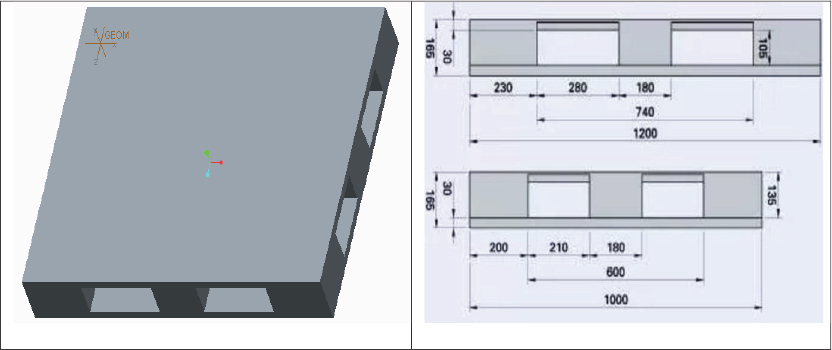
Fig. 10.
Design of a four-way pallet as per the ISO MH1-2016 standard in CAD software
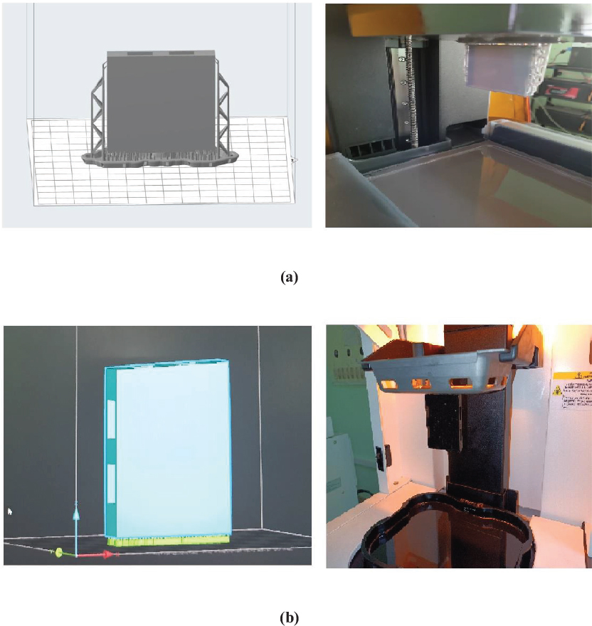
Fig. 11.
Pallet 3D printing in accordance with the ISO MH1-2016 standard for optimized values using (a) SLA (b) DLP
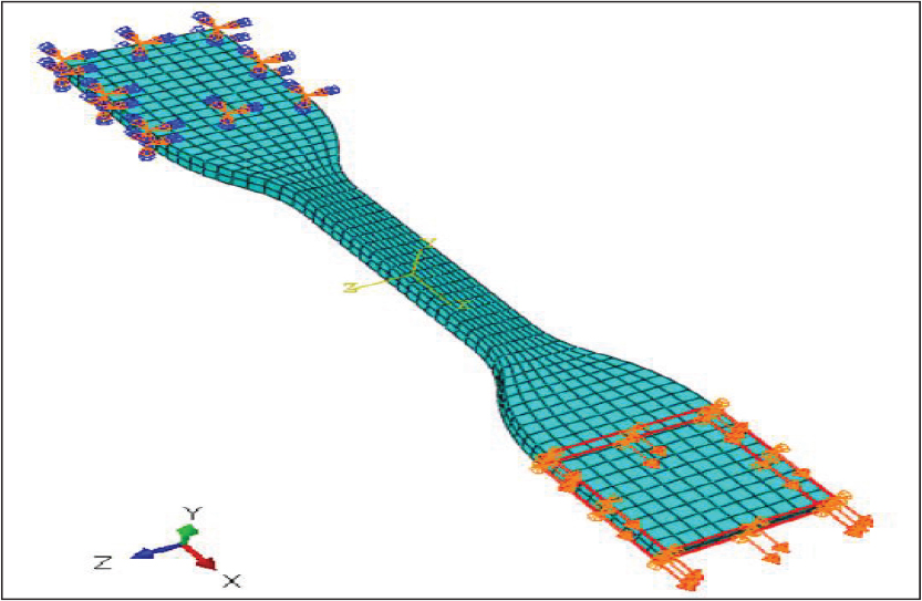
Fig. 12.
Finite element model of the ASTM D638 model in ABAQUS 6.14
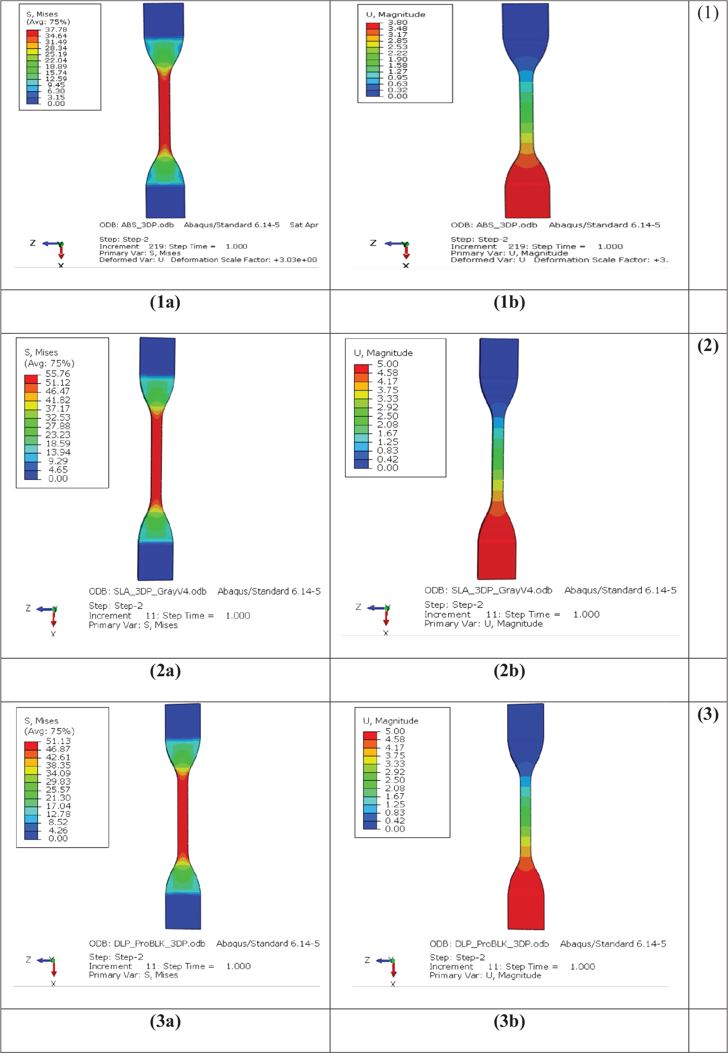
Fig. 13.
Simulations of 3D-printed test coupons for pallets corresponding to ABS (commercial replication: injection molding) (1); Pro-BLK-10 (SLA process) (2); and GrayV4 (DLP method) (3) for (a) maximum stress, (b) maximum deformation
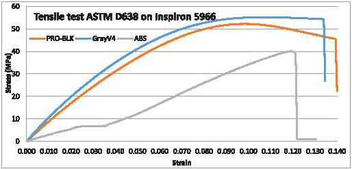
Fig. 14.
Experimental uniaxial tensile test results for ABS (commercial replication: injection moulding), Pro-BLK-10 (SLA process), and GrayV4 (DLP method)

Fig. 15.
Prismatic bar with concentrated force
Table 15.
Simulated versus physical uniaxial tensile test for ABS, Pro-BLK, and Grey V4 for injection molding, SLA, and DLP 3D printed samples
| Material | Parameter | Simulation | Analytical | Physical testing | Difference between simulation & testing (in %) |
|---|---|---|---|---|---|
| ABS | Stress (MPa) | 37.78 | 43.33 | 40.19 | 6.37 |
| Displacement(mm) | 1.80 | 1.88 | 1.62 | 10 | |
| GrayV4 | Stress (MPa) | 55.76 | 57.52 | 61.55 | 10.38 |
| Displacement(mm) | 2.89 | 2.36 | 3.25 | 12.45 | |
| ProBLK-10 | Stress (MPa) | 51.31 | 54.37 | 57.34 | 11.75 |
| Displacement(mm) | 2.88 | 2.69 | 3.19 | 10.76 |
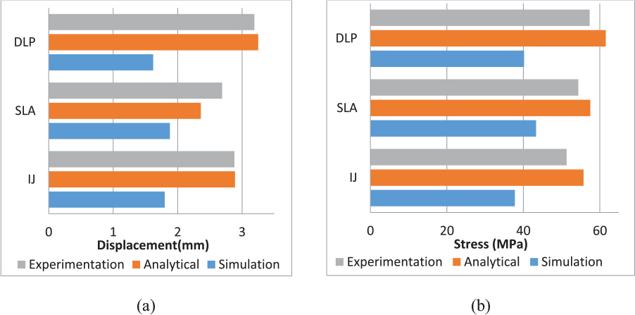
Fig. 16.
Simulated, experimental, and analytical uniaxial tensile test results for ABS, Pro-BLK, Grey V4 for injection molding, SLA and DLP 3D printed samples corresponding to (a) deflection (displacement) (b) stress
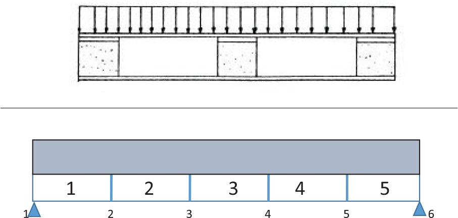
Fig. 17.
Coupon pallet 100 mm × 30 mm cross section being considered for (a) side view representing UDL load and (b) top deck of pallet corresponding to five beam elements
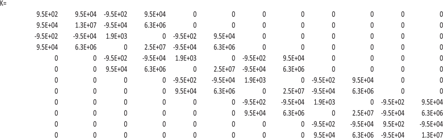
Fig. 18.
Global stiffness matrix of a simple supported beam with five elements corresponding to coupon pallet design
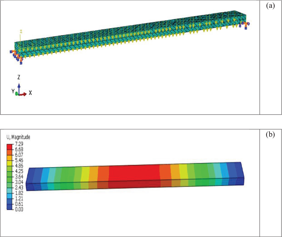
Fig. 19.
Beam representation for (a) 3D FEA model with fixed ends, (b) displacement module
Table 16.
Simulation and analytical values for displacement for a coupon sample
| Parameter | Simulation | Analytical | Difference between (percentage) simulation and analytical |
|---|---|---|---|
| Displacement (mm) | 7.29 | 7.8 | 6.5 |
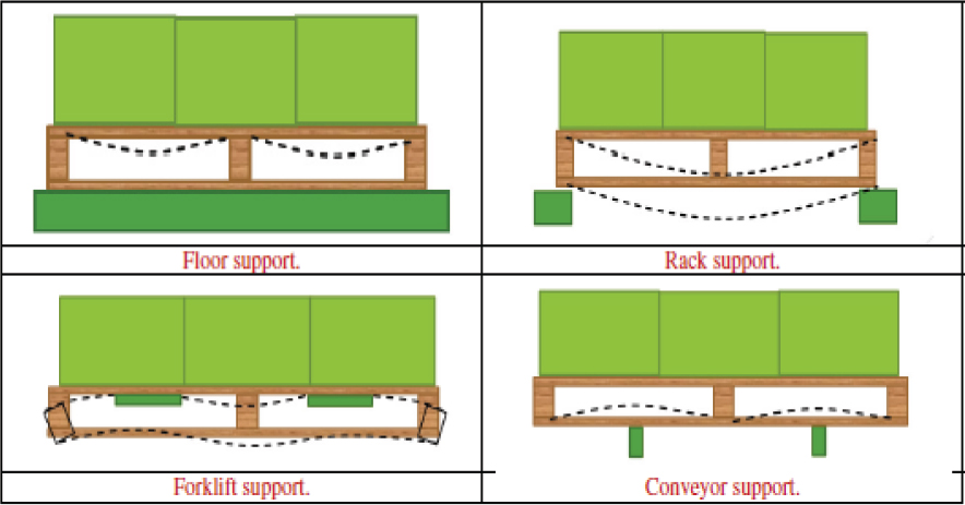
Fig. 20.
Basis of boundary conditions for pallet analysis
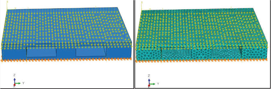
Fig. 21.
ISO Pallet CAD model and finite element model with load distribution
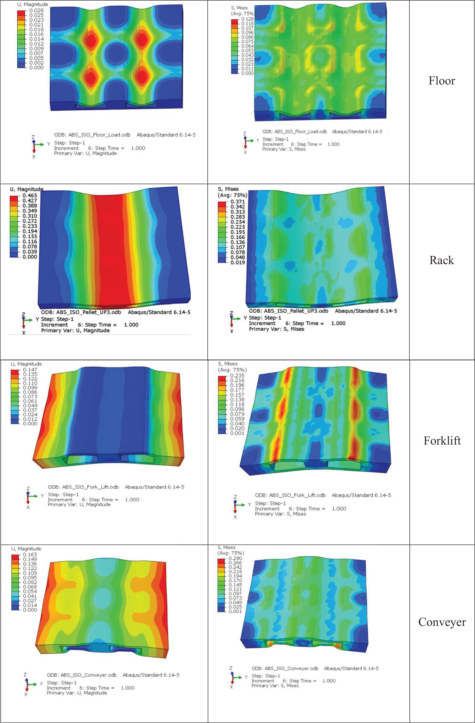
Fig. 22.
Displacement and stress contours: ISO pallet corresponding to ABS material
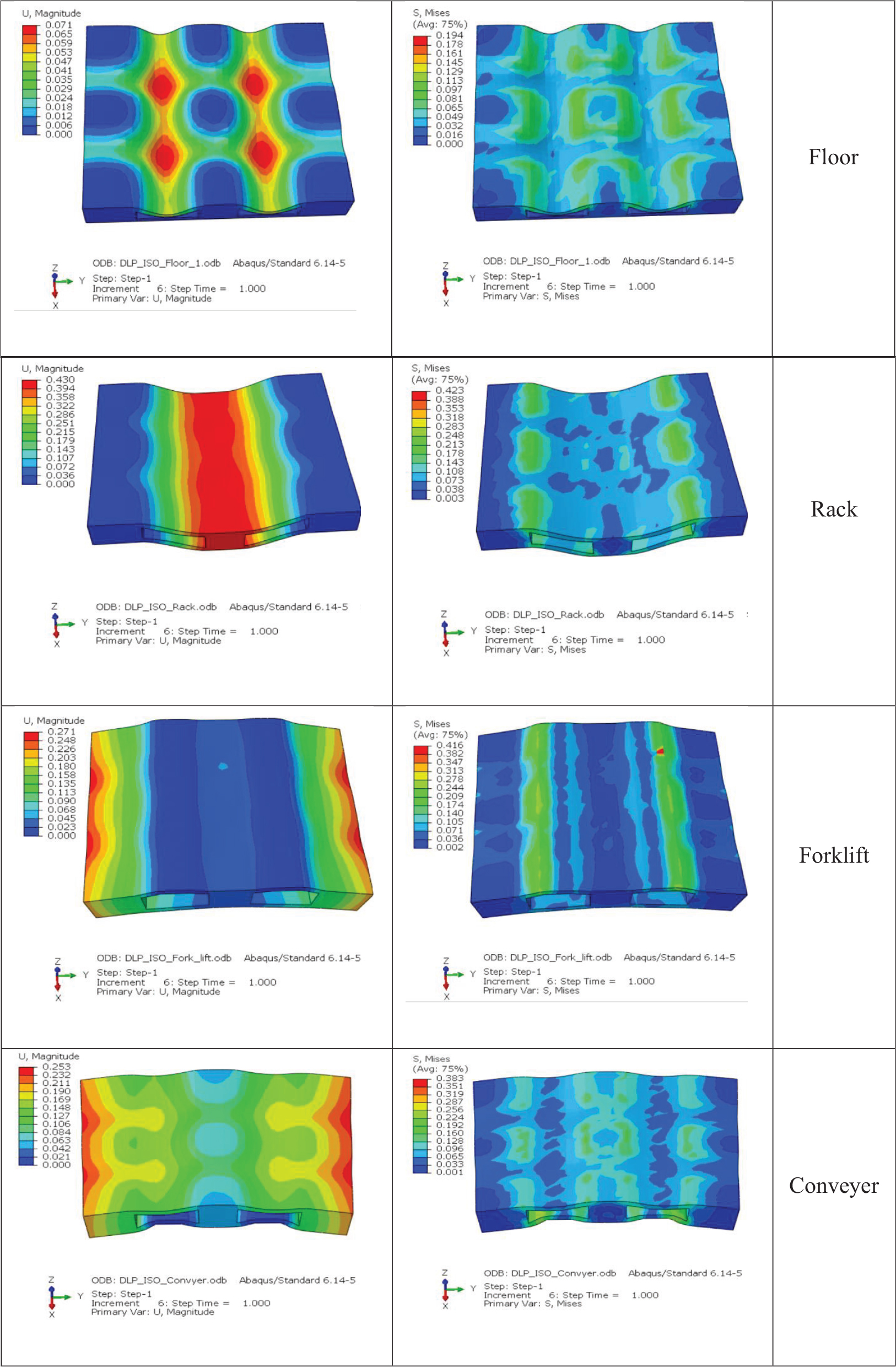
Fig. 23.
Displacement and stress contours: ISO pallet corresponding to DLP material
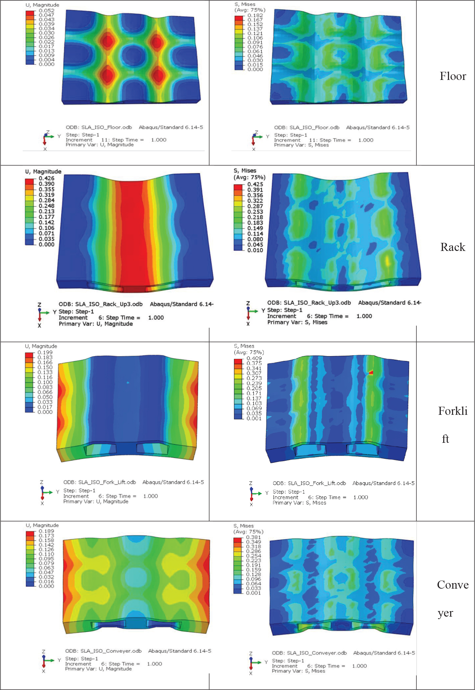
Fig. 24.
Displacement and stress contour: ISO pallet corresponding to SLA material
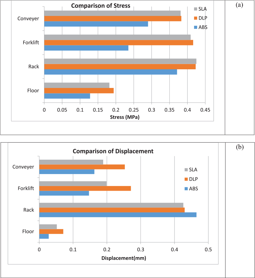
Fig. 25.
Comparisons of (a) von mises stress and (b) displacement on the basis of pallet supports
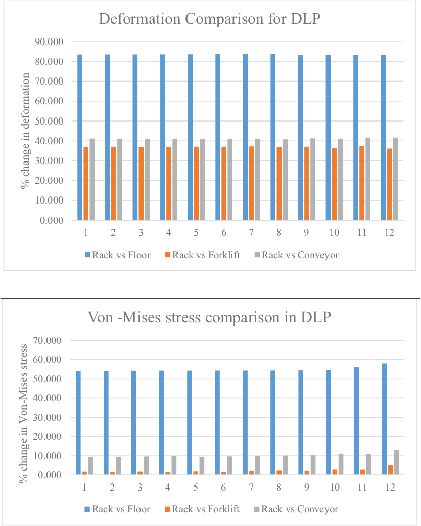
Fig. 26.
Comparisons of deflection and stresses for DLP-manufactured pallet
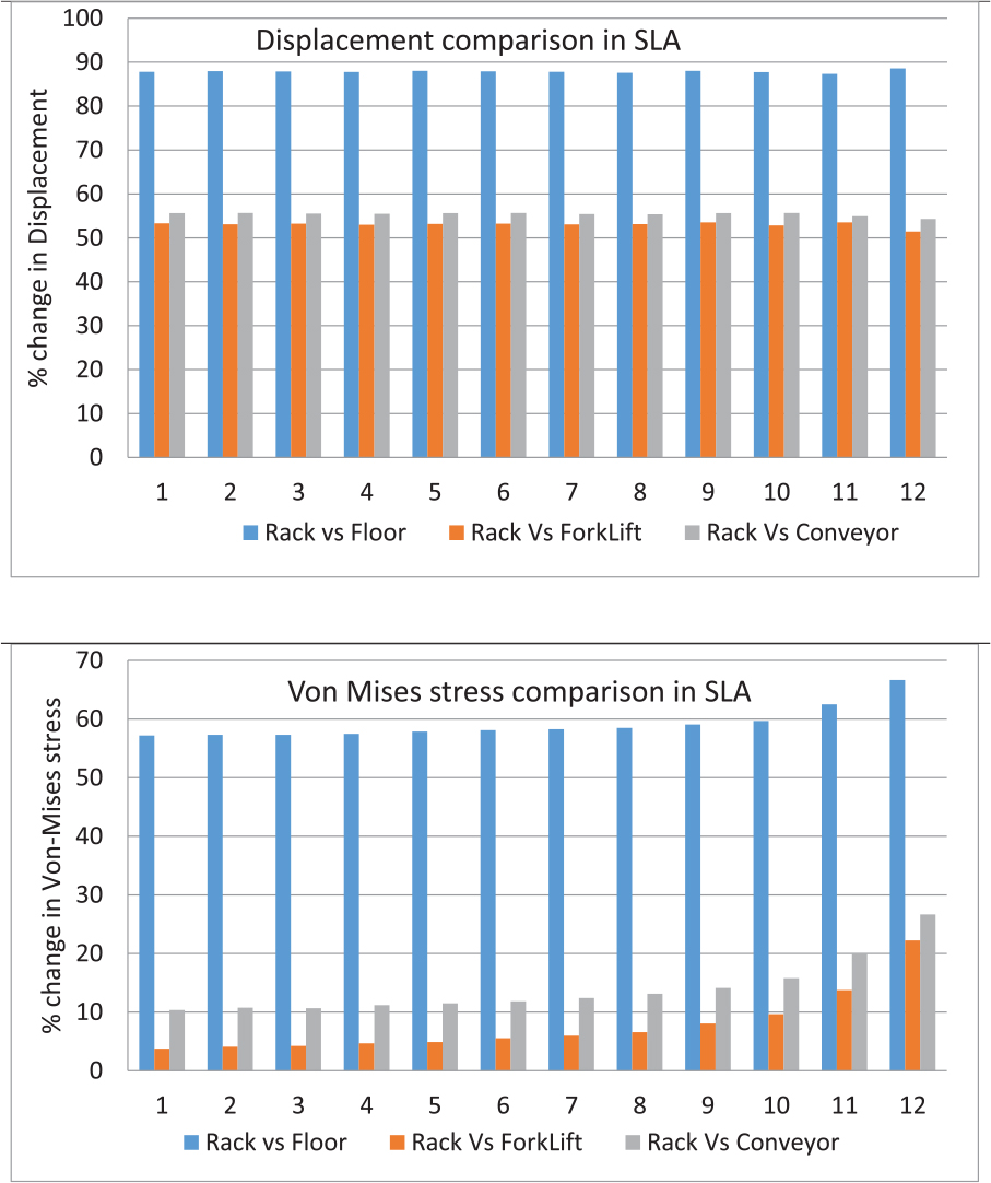
Fig. 27.
Comparisons of deflection and von mises stresses for SLA manufactured pallet
Table 17.
Comparison of rack support vs. floor support, rack support vs. forklift support, and rack support vs. conveyor support for DLP
| Comparison for deflection | Comparison for von mises stress | ||||
|---|---|---|---|---|---|
| Rack vs. floor | Rack vs. forklift | Rack vs. conveyor | Rack vs. floor | Rack vs. forklift | Rack vs. conveyor |
| 83.49 | 36.98 | 41.16 | 54.14 | 1.66 | 9.46 |
| 83.50 | 37.06 | 41.12 | 54.12 | 1.55 | 9.54 |
| 83.52 | 36.87 | 41.06 | 54.39 | 1.70 | 9.63 |
| 83.54 | 36.96 | 40.99 | 54.40 | 1.57 | 9.75 |
| 83.57 | 37.06 | 40.91 | 54.42 | 1.77 | 9.54 |
| 83.67 | 37.05 | 41.04 | 54.44 | 1.61 | 9.68 |
| 83.72 | 37.21 | 40.93 | 54.46 | 1.88 | 9.86 |
| 83.80 | 36.87 | 40.78 | 54.49 | 2.25 | 10.11 |
| 83.22 | 37.06 | 41.26 | 54.55 | 2.10 | 10.49 |
| 83.18 | 36.45 | 41.12 | 54.63 | 2.78 | 11.11 |
| 83.33 | 37.50 | 41.67 | 56.16 | 2.74 | 10.96 |
| 83.33 | 36.11 | 41.67 | 57.90 | 5.26 | 13.16 |
Table 18.
Comparison of rack support vs. floor support, rack support vs. forklift support, and rack support vs. conveyor support for SLA
| Comparison for deflection | Comparison for von misses stress | ||||
|---|---|---|---|---|---|
| Rack vs. floor | Rack vs. forklift | Rack vs. conveyor | Rack vs. floor | Rack vs. forklift | Rack vs. conveyor |
| 87.79 | 53.29 | 55.63 | 57.18 | 3.76 | 10.35 |
| 87.95 | 53.08 | 55.64 | 57.29 | 4.09 | 10.74 |
| 87.89 | 53.24 | 55.49 | 57.30 | 4.21 | 10.67 |
| 87.77 | 52.98 | 55.49 | 57.45 | 4.66 | 11.18 |
| 88.03 | 53.17 | 55.63 | 57.84 | 4.88 | 11.50 |
| 87.90 | 53.23 | 55.65 | 58.10 | 5.53 | 11.86 |
| 87.79 | 53.05 | 55.40 | 58.26 | 5.96 | 12.39 |
| 87.57 | 53.11 | 55.37 | 58.47 | 6.56 | 13.11 |
| 88.03 | 53.52 | 55.63 | 59.06 | 8.05 | 14.09 |
| 87.74 | 52.83 | 55.66 | 59.65 | 9.65 | 15.79 |
| 87.32 | 53.52 | 54.93 | 62.50 | 13.75 | 20.00 |
| 88.57 | 51.43 | 54.29 | 66.67 | 22.22 | 26.67 |
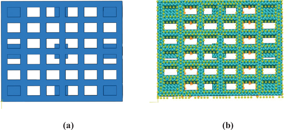
Fig. 28.
(a) CAD model (b) Finite element model for optimized pallet design
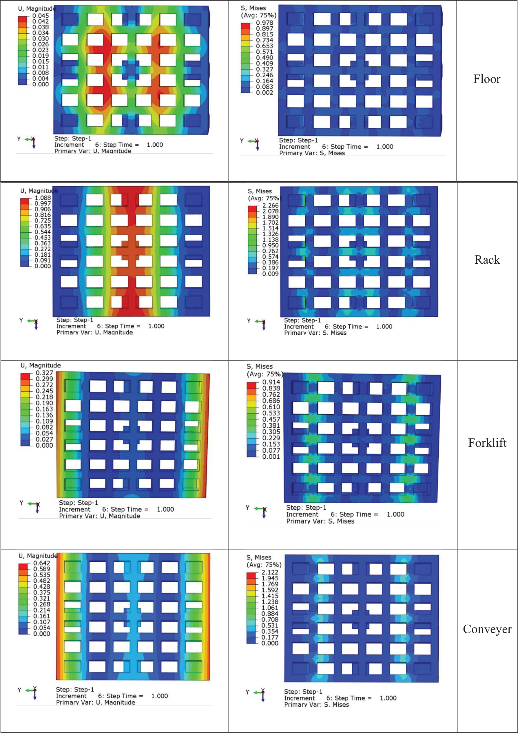
Fig. 29.
Displacement and stress contour: optimized pallet design (ABS material)
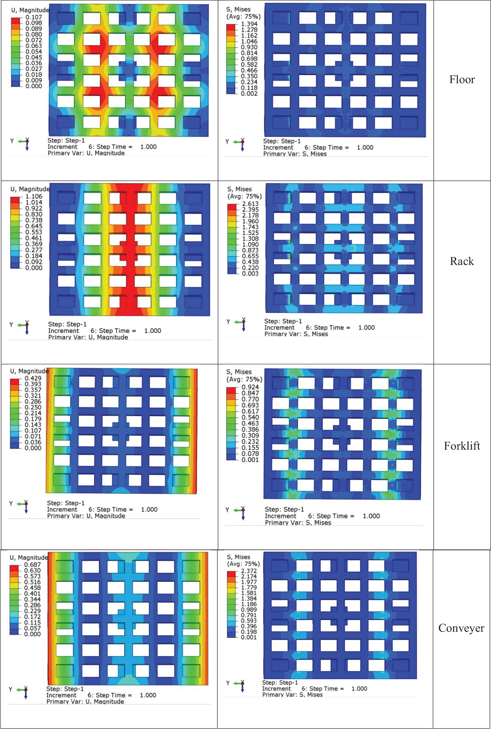
Fig. 30.
Displacement and stress contour: optimized pallet design (DLP material)
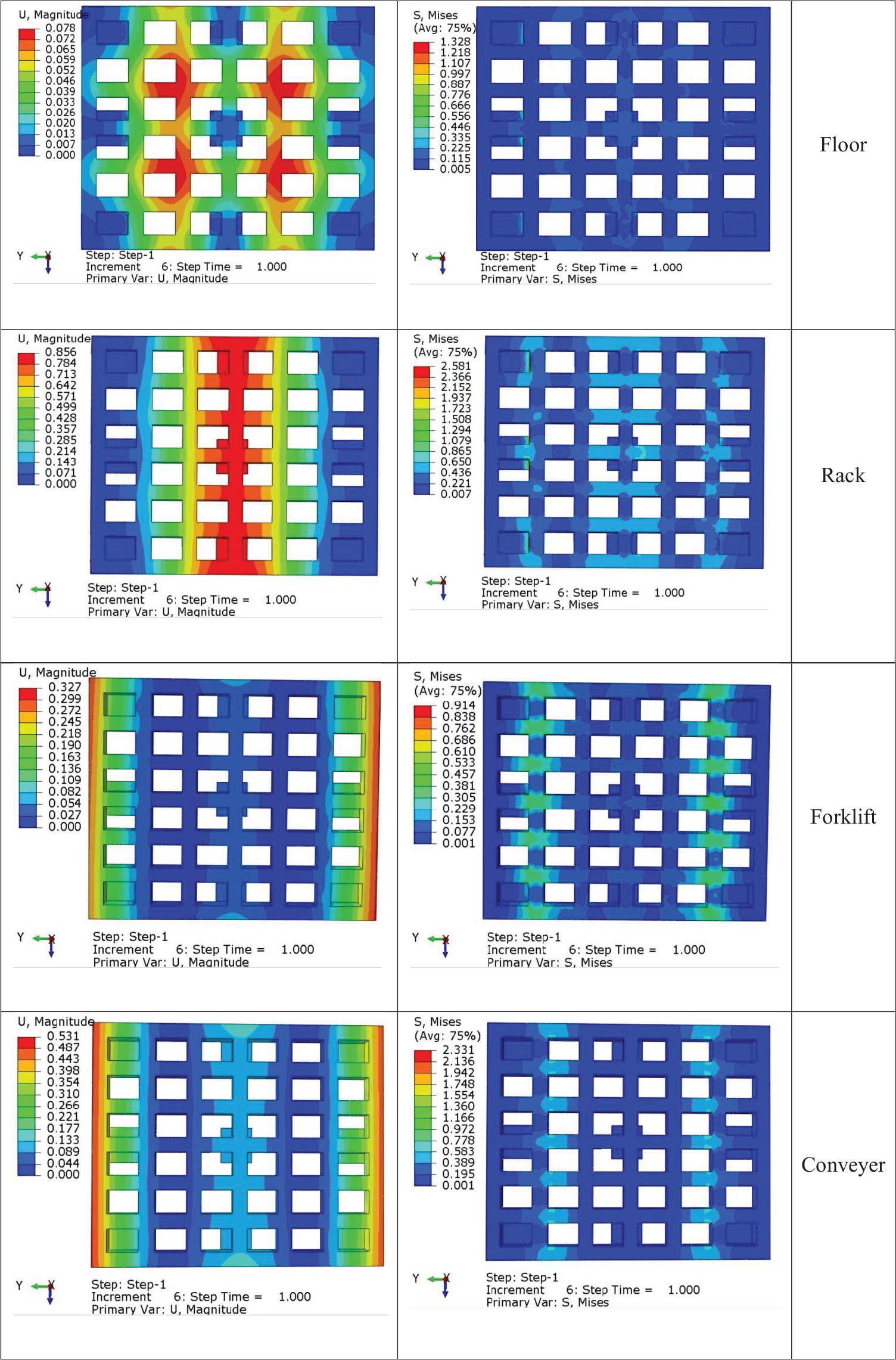
Fig. 31.
Displacement and stress contour: optimized pallet design (SLA material)
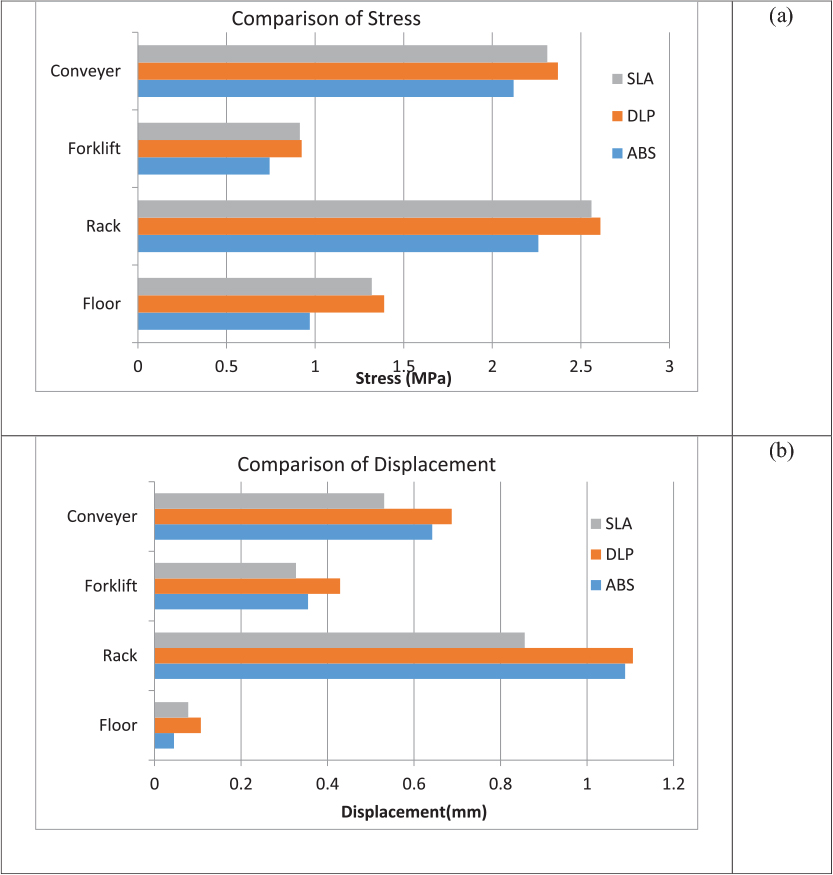
Fig. 32.
Optimized pallet analysis correlation to (a) von mises stress (b) deflection
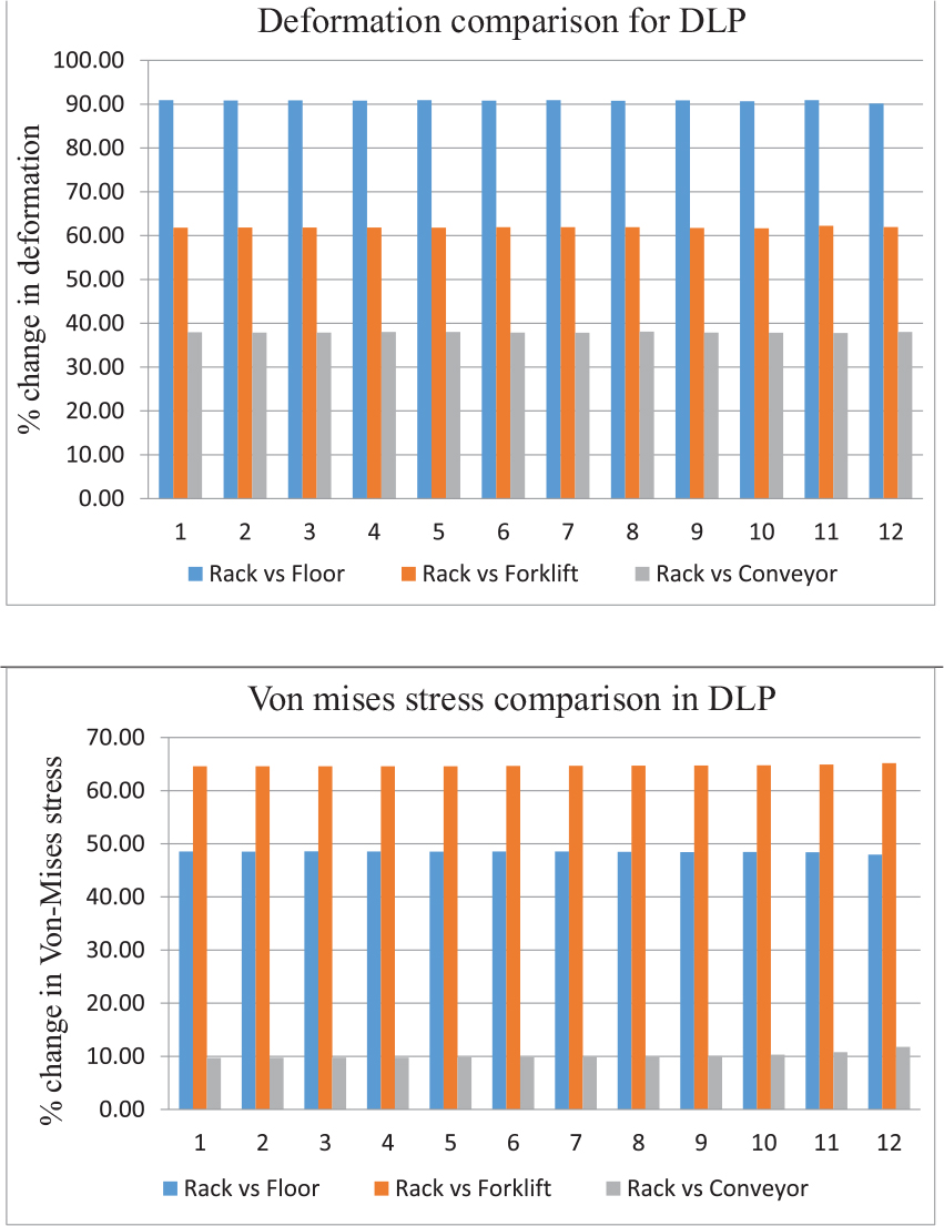
Fig. 33.
Deflection and stresses for DLP-manufactured pallet
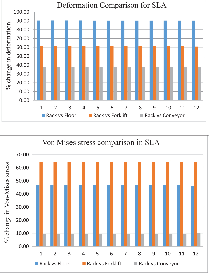
Fig. 34.
Deflection and von mises stresses for SLAmanufactured pallet
Table 19.
Comparison of rack support vs. floor support, rack support vs. forklift support, and rack support vs. conveyor support for DLP
| Comparison for deflection | Comparison for von mises stress | ||||
|---|---|---|---|---|---|
| Rack vs. floor | Rack vs. forklift | Rack vs. conveyor | Rack vs. floor | Rack vs. forklift | Rack vs. conveyor |
| 90.89 | 61.80 | 37.97 | 48.55 | 64.59 | 9.69 |
| 90.82 | 61.86 | 37.88 | 48.52 | 64.58 | 9.72 |
| 90.88 | 61.85 | 37.87 | 48.56 | 64.59 | 9.76 |
| 90.81 | 61.84 | 38.01 | 48.53 | 64.58 | 9.76 |
| 90.89 | 61.82 | 38.00 | 48.52 | 64.60 | 9.81 |
| 90.78 | 61.92 | 37.88 | 48.54 | 64.66 | 9.81 |
| 90.89 | 61.92 | 37.85 | 48.53 | 64.68 | 9.89 |
| 90.76 | 61.90 | 38.10 | 48.47 | 64.69 | 9.92 |
| 90.88 | 61.75 | 37.89 | 48.44 | 64.74 | 10.06 |
| 90.65 | 61.68 | 37.85 | 48.46 | 64.77 | 10.31 |
| 90.91 | 62.24 | 37.76 | 48.39 | 64.91 | 10.78 |
| 90.14 | 61.97 | 38.03 | 47.96 | 65.16 | 11.76 |
Table 20.
Comparison of rack support vs. floor support, rack support vs. forklift support, and rack support vs. conveyor support for SLA
| Comparison for deflection | Comparison for von-misses stress | ||||
|---|---|---|---|---|---|
| Rack vs. floor | Rack vs. forklift | Rack vs. conveyor | Rack vs. floor | Rack vs. forklift | Rack vs. conveyor |
| 90.33 | 61.21 | 37.88 | 46.65 | 64.64 | 9.22 |
| 90.34 | 61.24 | 37.87 | 46.64 | 64.63 | 9.23 |
| 90.35 | 61.28 | 37.85 | 46.65 | 64.65 | 9.23 |
| 90.36 | 61.33 | 37.83 | 46.63 | 64.64 | 9.23 |
| 90.24 | 61.25 | 37.94 | 46.64 | 64.60 | 9.29 |
| 90.23 | 61.24 | 37.83 | 46.62 | 64.59 | 9.25 |
| 90.24 | 61.30 | 37.79 | 46.64 | 64.60 | 9.33 |
| 90.24 | 61.17 | 37.96 | 46.61 | 64.59 | 9.27 |
| 90.24 | 61.25 | 37.94 | 46.62 | 64.60 | 9.39 |
| 90.25 | 61.37 | 37.91 | 46.56 | 64.58 | 9.47 |
| 90.22 | 61.41 | 37.50 | 46.58 | 64.61 | 9.59 |
| 90.22 | 60.87 | 38.04 | 46.36 | 64.55 | 10.00 |
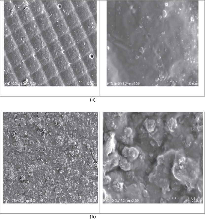
Fig. 35.
SEM images for additive-manufactured (a) DLP (b) SLA pallet
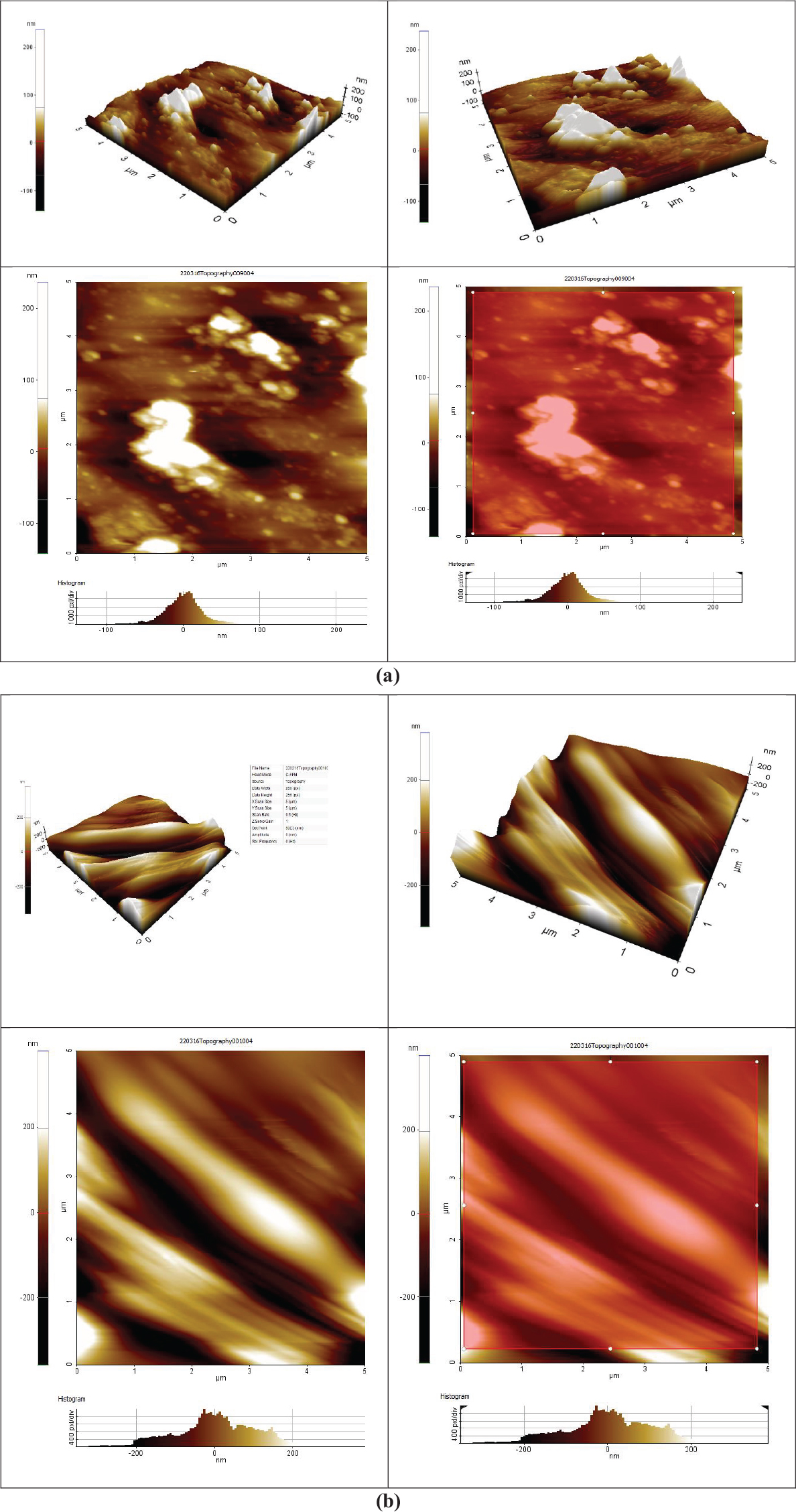
Fig. 36.
AFM plots of additive-manufactured (a) DLP (b) SLA pallets
Table 21.
Roughness values obtained from AFM for DLP and SLA pallets
| S. No. | Pallet-making process | Roughness factor (nm) |
|---|---|---|
| 1. | DLP | 95.18 |
| 2. | SLA | 207.35 |
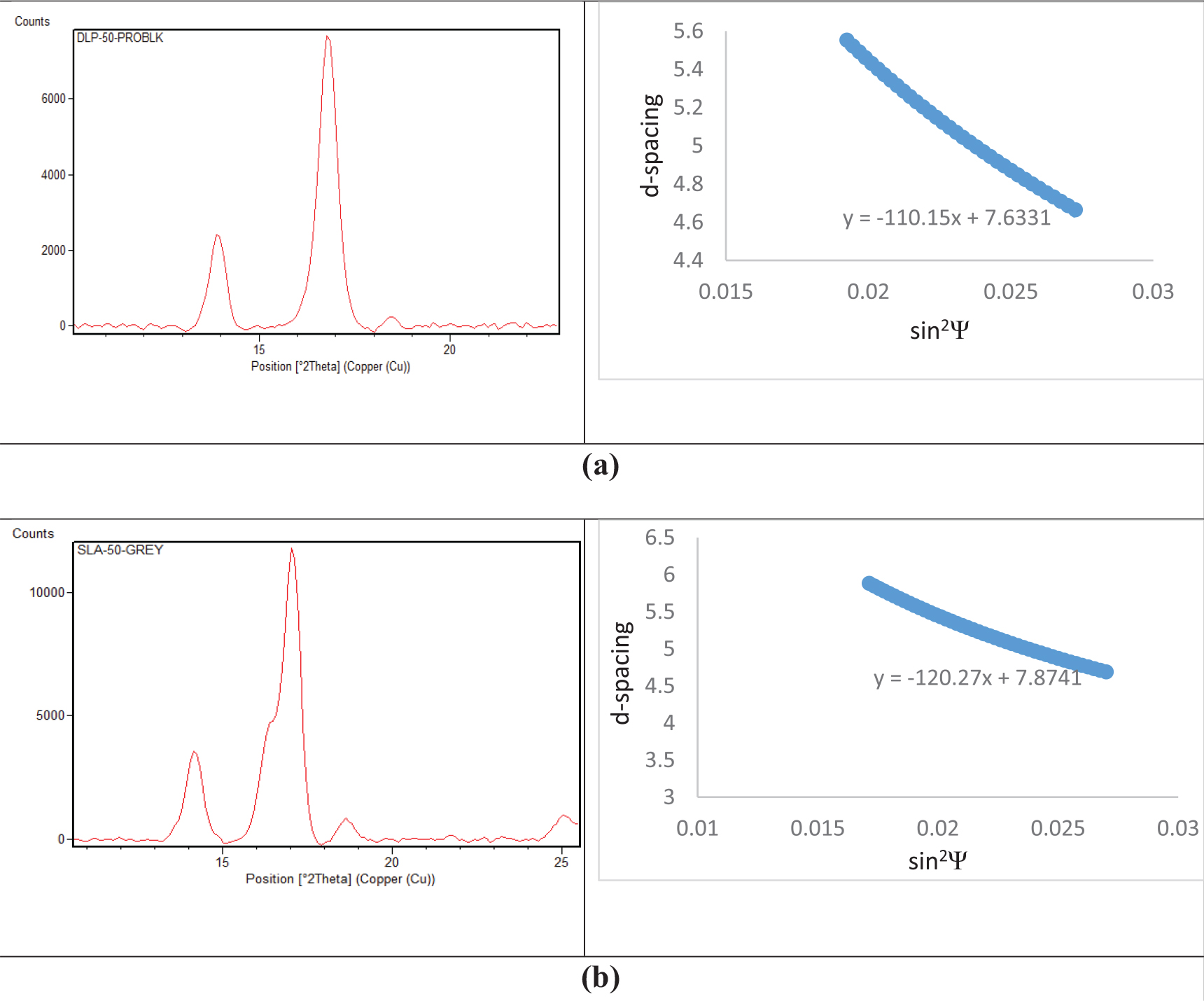
Fig. 37.
XRD plots for 3D printed pallets availing (a) DLP (b) SLA