
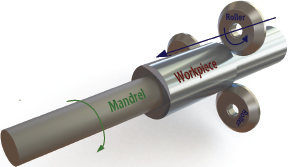
Fig. 1.
Schematic of flow-forming process
Table 1.
The chemical composition of the AA 6060 tested
| Element | Si | Mg | Fe | Mn | Cr | Ti | Cu | Zn |
|---|---|---|---|---|---|---|---|---|
| Wt% | 0.55 ± 0.03 | 0.381 ± 0.01 | 0.088 ± 0.02 | 0.063 ± 0.04 | 0.014 ± 0.00 | >0.010 ± 0.00 | 0.002 ± 0.00 | 0.001 ± 0.00 |
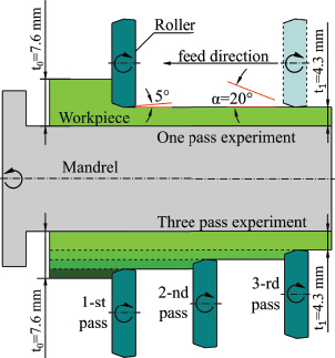
Fig. 2.
Diagram of the flow forming process. The top half of the figure shows the trajectory of the rollers in one pass, while the bottom half of the figure shows the trajectory for 3-pass experiment
Table 2.
The mechanical properties determined in the static tensile test
| Tensile speed [mm/min] | Rp0.2 ± URp0.2 [MPa] | Rm ± URm [MPa] | A50 mm ± UA50 mm [%] | Z ± UZ [%] |
|---|---|---|---|---|
| 0.5 | 137 ± 12 | 176 ± 12 | 20.1 ± 1.0 | 64.8 ± 2.5 |
| 5 | 137 ± 12 | 179 ± 12 | 19.4 ± 1.9 | 61.7 ± 4.4 |
| 50 | 135 ± 12 | 177 ± 12 | 20.9 ± 2.5 | 61.9 ± 6.5 |
| 500 | 141 ± 12 | 182 ± 12 | 16.6 ± 5.7 | 57.0 ± 3.7 |
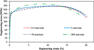
Fig. 3.
The tensile curve for specimens deformed at the speed of v = 0.5-500 mm/min
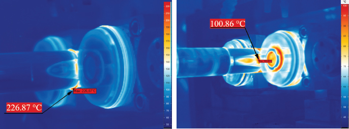
Fig. 4.
Temperature distribution (°C) during the forming in 1 pass (left) and in the first pass of 3 passes experiment (right)
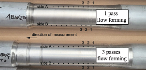
Fig. 5.
The AA 6060 material after flow forming
Table 3.
A summary of the results of the flow forming of aluminum alloy 6060
| No. | Type of experiment | t0 (mm) | t1 (mm) | Δt = t0 -11 (mm) | Average Δt (mm) | εt (%) | Average εt(%) |
|---|---|---|---|---|---|---|---|
| 1 | 1 pass | 7.55 | 4.98 | 2.57 | 2.62 | 34% | 35% |
| 2 | 1 pass | 7.7 | 4.96 | 2.74 | 36% | ||
| 3 | 1 pass | 7.6 | 5.04 | 2.56 | 34% | ||
| 4 | 3 passes | 7.55 | 4.54 | 3.01 | 3.04 | 40% | 40% |
| 5 | 3 passes | 7.65 | 4.72 | 2.93 | 38% | ||
| 6 | 3 passes | 7.55 | 4.37 | 3.18 | 42% |
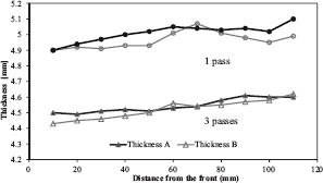
Fig. 6.
The wall thickness distribution measured after 1-pass and 3-pass flow forming
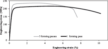
Fig. 7.
A diagram showing the results of tensile testing of the specimens after 1-pass and 3-pass flow forming
Table 4.
Strength properties of specimens after the forming
| Number of forming passes | Δt (mm) | Rp0,2 (MPa) | Rm (MPa) | A50 mm (%) | Z(%) | HV |
|---|---|---|---|---|---|---|
| 1 | 2.62 | 199–207 | 216–224 | 10.2–12.7 | 45.7–53.4 | 73.0 |
| 3 | 3.04 | 211–226 | 220–239 | 7.1–12.1 | 50.4–60.8 | 78.7 |
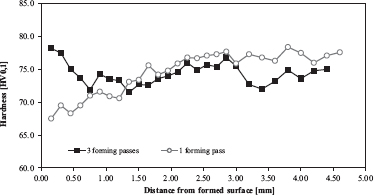
Fig. 8.
Results of microhardness measurements on the pipe cross-section after the flow-forming process in 1 pass and 3 passes
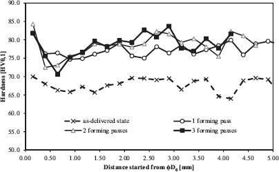
Fig. 9.
The microhardness distribution over the thickness of the material formed
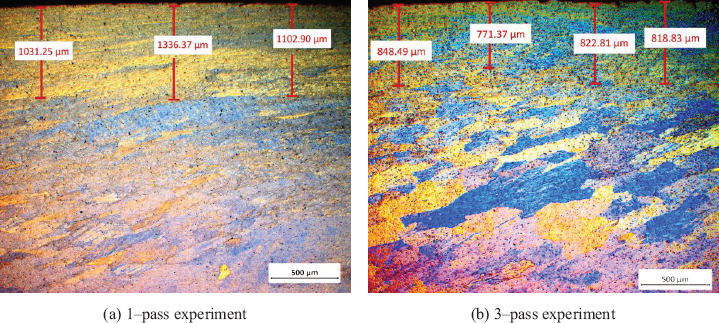
Fig. 10.
The microstructure of the specimen after flow forming: (a) 1-pass experiment, (b) 3-pass experiment
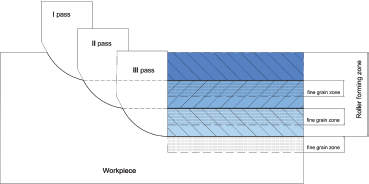
Fig. 11.
Diagram of sample’s microstructure individual flow forming pass
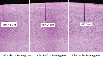
Fig. 12.
The microstructure of the product after individual flow-forming passes
Table 5.
Hardness properties of specimens after the flow forming
| Distance from surface (mm) | With cooling agent (HV) | Without cooling agent (HV) |
|---|---|---|
| 0.2 | 73.5 | 78.2 |
| 0.4 | 73.4 | 77.5 |
| 0.6 | 74.6 | 75.0 |
| 0.8 | 74.5 | 74.7 |
| 1.0 | 74.6 | 74.3 |
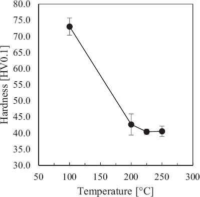
Fig. 13.
The impact of temperatures 100, 200, 225, and 250°C on the microhardness of aluminum alloy 6060