
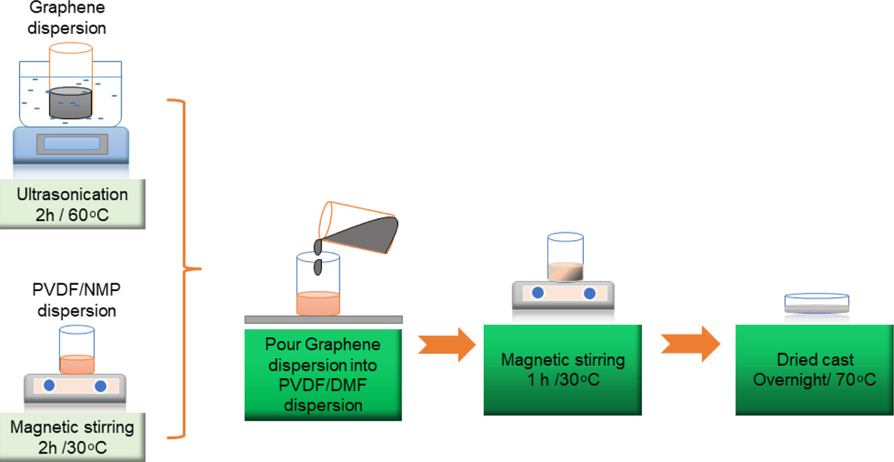
Fig. 1
A schematic illustration for the synthesis of PVDF/G composite film. PVDF, polyvinylidene fluoride; PVDF/G, polyvinylidene fluoride infused graphene
Table 1
A comparison of uniaxial tensile properties of native heart valves, blood vessels, PVDF, and PVDF-G composites
| Samples (thickness ~15 mm) | Ultimate tensile strength, σ (MPa) | Strain, ɛ (%) | Young's modulus, E (MPa) |
|---|---|---|---|
| Human aortic valve [28] | 2.60 | 22.00 | 15.00 |
| Porcine aortic valve [29] | 1.30 | 10.80 | 7.80 |
| Blood vessel [30] | 0.20–0.60 | - | 2.00–6.00 |
| PVDF | 23.40 | 69.30 | 417.64 |
| PVDF/G-1.0 wt.% | 19.29 | 4.68 | 492.64 |
| PVDF/G-1.5 wt.% | 90.24 | 2.30 | 5,720.88 |
| PVDF/G-2.0 wt.% | 56.59 | 3.67 | 2,740.64 |
[i] PVDF, polyvinylidene fluoride; PVDF/G, polyvinylidene fluoride infused graphene
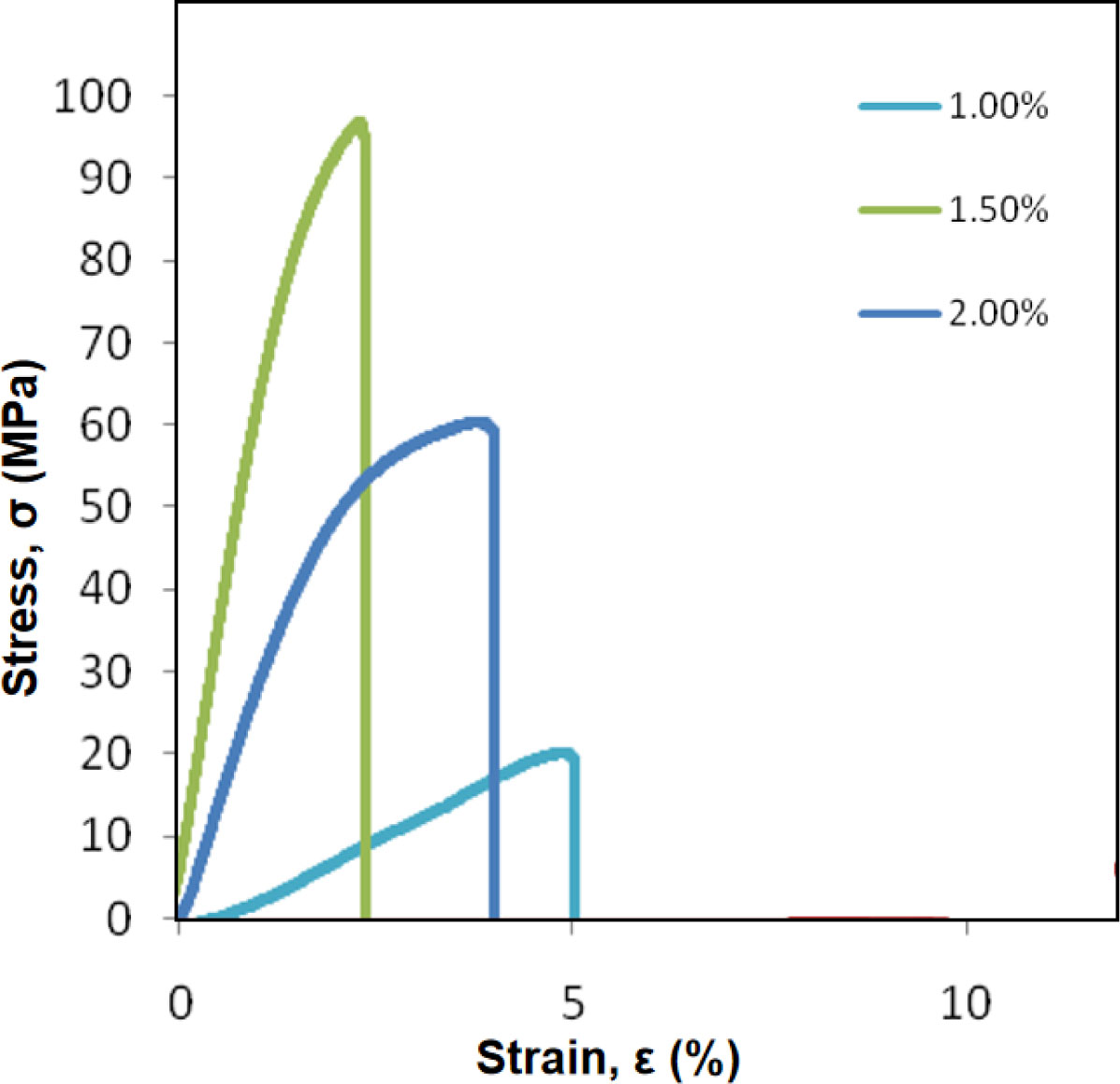
Fig. 2
Stress (MPa) versus strain (%) of PVDF/G composites. PVDF/G, polyvinylidene fluoride infused graphene
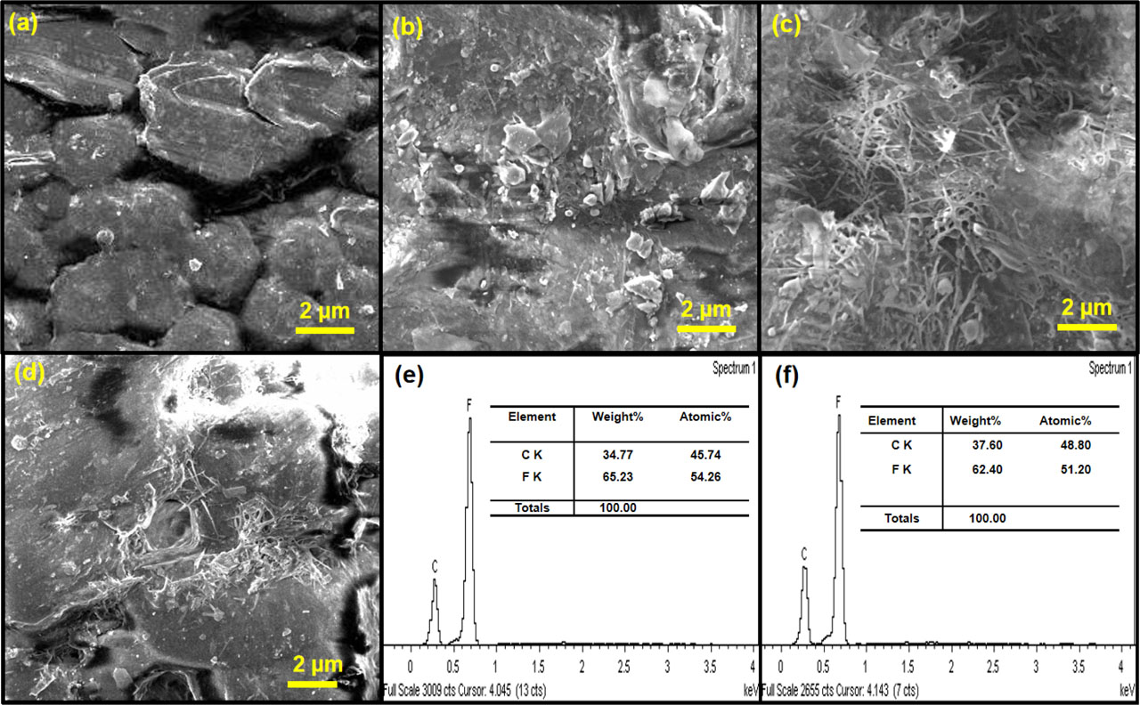
Fig. 3
FESEM images of (A) pure PVDF, (B) PVDF/G-1.0%, (C) PVDF/G-1.5%, (D) PVDF/G-2.0%, (E) EDX analysis of pure PVDF, and (F) EDX analysis of the PVDF/G composite film. EDX, energy-dispersive X-ray spectroscopy; PVDF, polyvinylidene fluoride; PVDF/G, polyvinylidene fluoride infused graphene
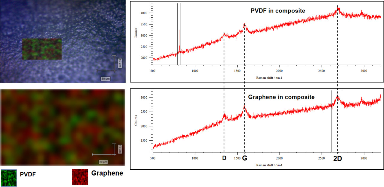
Fig. 4
Raman mapping of PVDF/G composite. PVDF/G, polyvinylidene fluoride infused graphene
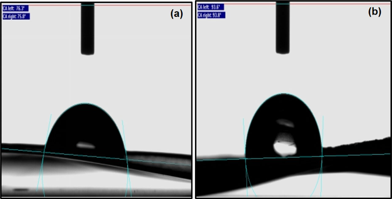
Fig. 5
Water CA of (A) pure PVDF and (B) PVDF/G composite. CA, contact angle; PVDF, polyvinylidene fluoride; PVDF/G, polyvinylidene fluoride infused graphene