
Table 1
The chemical make-up of 6061 Al-alloy
| Element | Mg | Si | Fe | Cu | Mn | Zn | Cr | Ti | Al |
|---|---|---|---|---|---|---|---|---|---|
| Wt.% | 1.1 | 0.55 | 0.4 | 0.10 | 0.9 | 0.25 | 0.04 | 0.12 | Remainder |
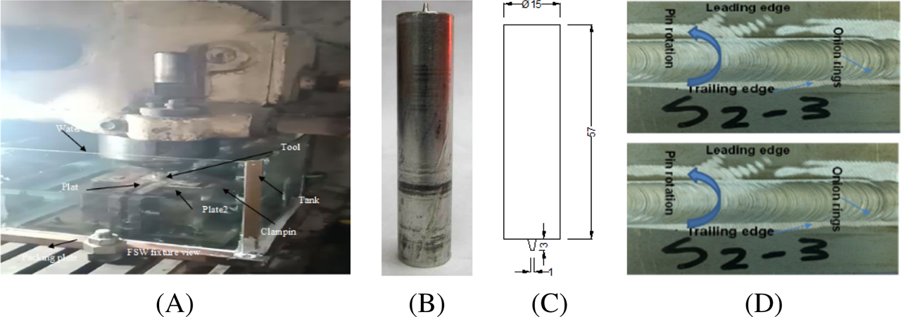
Fig. 1
Schematic representation of UWFSW (A) UWFSW welding fixture. (B) Photo of a tool (C) tool dimension (D) specimens of 6061/18% SiC AMC
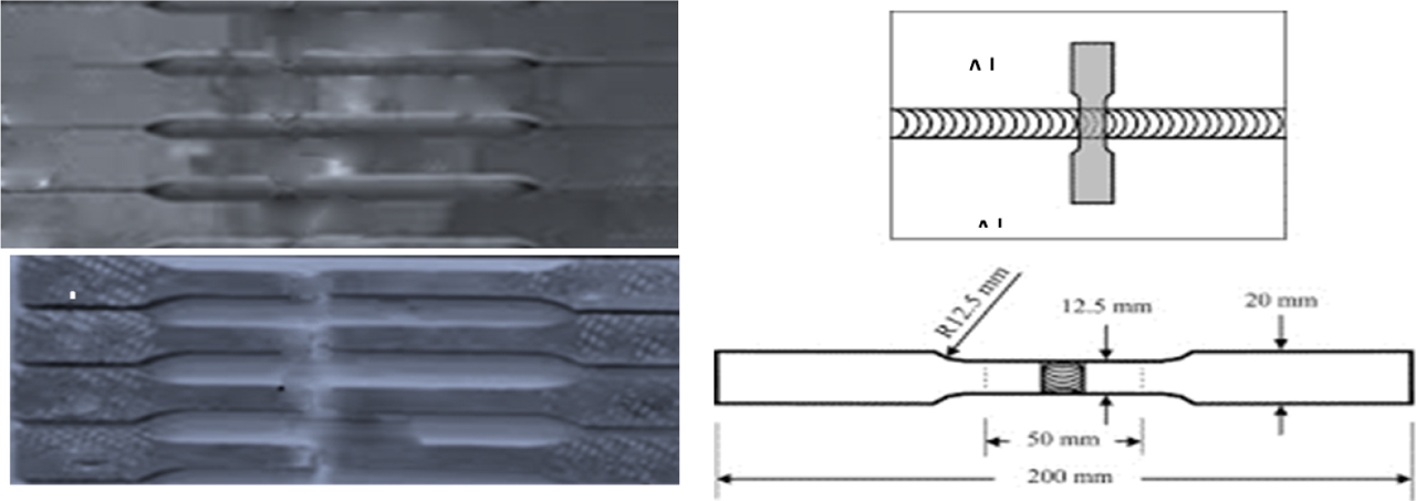
Fig. 2
(A) Photos of the specimens after tensile test. (B) Photos of the specimens before tensile test. (C) Dimensions of tensile test specimens (dimensions are in millimeter)
Table 2
UWFSW process parameters and their limits
| Level | |||
|---|---|---|---|
| Parameter | −1 | 0 | 1 |
| Silicon carbide (SiC) (%) | 5 | 10 | 18 |
| Rotation speed (N) (rpm) | 1,000 | 1,400 | 1,800 |
| Travel speed (S) (mm/min) | 10 | 20 | 30 |
Table 3
Full factorial design matrix
| Run | SiC | N | S | UTS (MPa) code | VHNode |
|---|---|---|---|---|---|
| 1 | 5 | 1,000 | 10 | 205.00 | 64.544 |
| 2 | 10 | 1,000 | 10 | 196.00 | 55.243 |
| 3 | 18 | 1,000 | 10 | 190.00 | 52.942 |
| 4 | 5 | 1,000 | 20 | 200.00 | 55.980 |
| 5 | 10 | 1,000 | 20 | 190.00 | 53.679 |
| 6 | 18 | 1,000 | 20 | 180.00 | 51.378 |
| 7 | 5 | 1,000 | 30 | 190.00 | 55.198 |
| 8 | 10 | 1,000 | 30 | 185.00 | 52.897 |
| 9 | 18 | 1,000 | 30 | 174.00 | 50.596 |
| 10 | 5 | 1,400 | 10 | 202.00 | 56.113 |
| 11 | 10 | 1,400 | 10 | 186.40 | 53.812 |
| 12 | 18 | 1,400 | 10 | 174.70 | 51.511 |
| 13 | 5 | 1,400 | 20 | 195.30 | 54.548 |
| 14 | 10 | 1,400 | 20 | 183.70 | 52.247 |
| 15 | 18 | 1,400 | 20 | 172.30 | 49.946 |
| 16 | 5 | 1,400 | 30 | 193.10 | 53.766 |
| 17 | 10 | 1,400 | 30 | 180.03 | 51.465 |
| 18 | 18 | 1,400 | 30 | 170.32 | 49.164 |
| 19 | 5 | 1,800 | 10 | 196.00 | 56.113 |
| 20 | 10 | 1,800 | 10 | 185.10 | 52.380 |
| 21 | 18 | 1,800 | 10 | 176.20 | 50.079 |
| 22 | 5 | 1,800 | 20 | 191.30 | 53.117 |
| 23 | 10 | 1,800 | 20 | 184.20 | 50.816 |
| 24 | 18 | 1,800 | 20 | 171.20 | 48.515 |
| 25 | 5 | 1,800 | 30 | 187.10 | 52.335 |
| 26 | 10 | 1,800 | 30 | 181.10 | 50.034 |
| 27 | 18 | 1,800 | 30 | 166.30 | 47.732 |
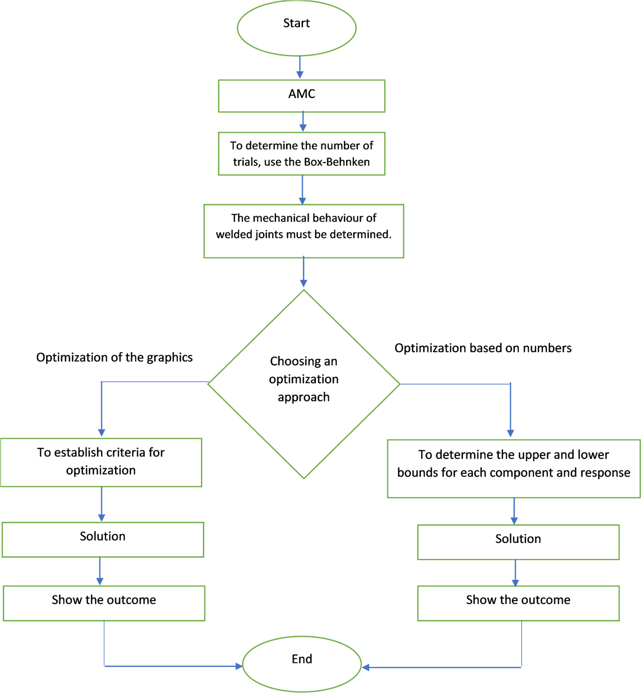
Fig. 3
Experimentation flowchart of the UWFSW
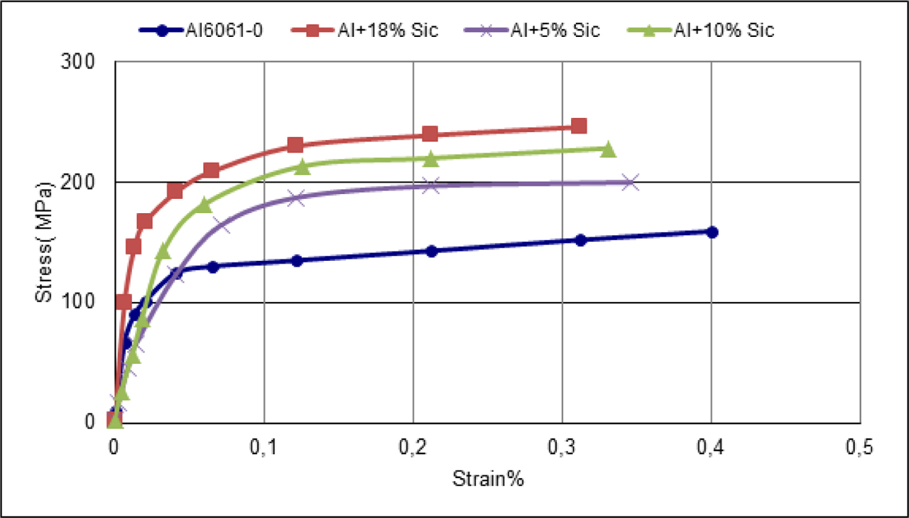
Fig. 4
Stress–strain curve of unwelded AA 6061 Al-SiC alloy specimens from the tensile test
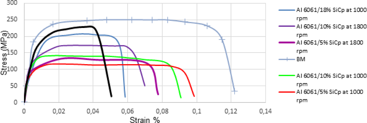
Fig. 5
Stress-strain curve of welded AA 6061 Aluminium-silicon carbide alloy specimens from the tensile test for weld speed 10 mm/min
Table 4
ANOVA results for UTS
| Exporter | Squares of sum | df | Square of mean | F-value | p-value | |
|---|---|---|---|---|---|---|
| Model | 2,637.03 | 9 | 293.00 | 52.07 | <0.0001 | Significant |
| A-SiC | 1,896.87 | 1 | 1,896.87 | 337.08 | <0.0001 | |
| B-N | 73.62 | 1 | 273.62 | 48.62 | <0.0001 | |
| C-S | 397.11 | 1 | 397.11 | 70.57 | <0.0001 | |
| AB | 6.56 | 1 | 6.56 | 1.17 | 0.2952 | |
| AC | 1.37 | 1 | 1.37 | 0.24 | 0.6285 | |
| BC | 30.72 | 1 | 30.72 | 5.46 | 0.0320 | |
| A2 | 47.11 | 1 | 47.11 | 8.37 | 0.0101 | |
| B2 | 19.92 | 1 | 19.92 | 3.54 | 0.0771 | |
| C2 | 0.10 | 1 | 0.10 | 0.018 | 0.8943 | |
| Residual | 95.66 | 17 | 5.63 | |||
| Cor Total | 2,732.69 | 26 |
Table 5
ANOVA results for microhardness
| Exporter | Squares of sum | df | Square of mean | F-value | p-value | |
|---|---|---|---|---|---|---|
| Model | 260.47 | 9 | 28.94 | 21.80 | <0.0001 | Significant |
| A-SiC | 138.06 | 1 | 138.06 | 104.02 | <0.0001 | |
| B-N | 56.45 | 1 | 56.45 | 42.53 | <0.0001 | |
| C-S | 51.50 | 1 | 51.50 | 38.80 | <0.0001 | |
| AB | 2.94 | 1 | 2.94 | 2.22 | 0.1548 | |
| AC | 6.75 | 1 | 6.75 | 5.09 | 0.0376 | |
| BC | 2.58 | 1 | 2.58 | 1.95 | 0.1810 | |
| A2 | 0.17 | 1 | 0.17 | 0.13 | 0.7234 | |
| B2 | 1.32 | 1 | 1.32 | 0.99 | 0.3331 | |
| C2 | 4.43 | 1 | 4.43 | 3.34 | 0.0852 | |
| Residual | 22.56 | 17 | 1.33 | |||
| 283.03 | 26 |
Table 6
The optimization criteria that were applied in this study
| Parameters/responses of the process | Goal | The bare minimum | The bare maximum | Significance |
|---|---|---|---|---|
| A:SiC | Is in range | 6.03417 | 16.9658 | 3 |
| B:N | Is in range | 10,063 | 1,736.36 | 3 |
| C:S | Is in range | 10 | 28.409 | 3 |
| UTS | Maximize | 186.3 | 202.9 | 3 |
| WNH | Maximize | 47.732 | 64.544 | 3 |
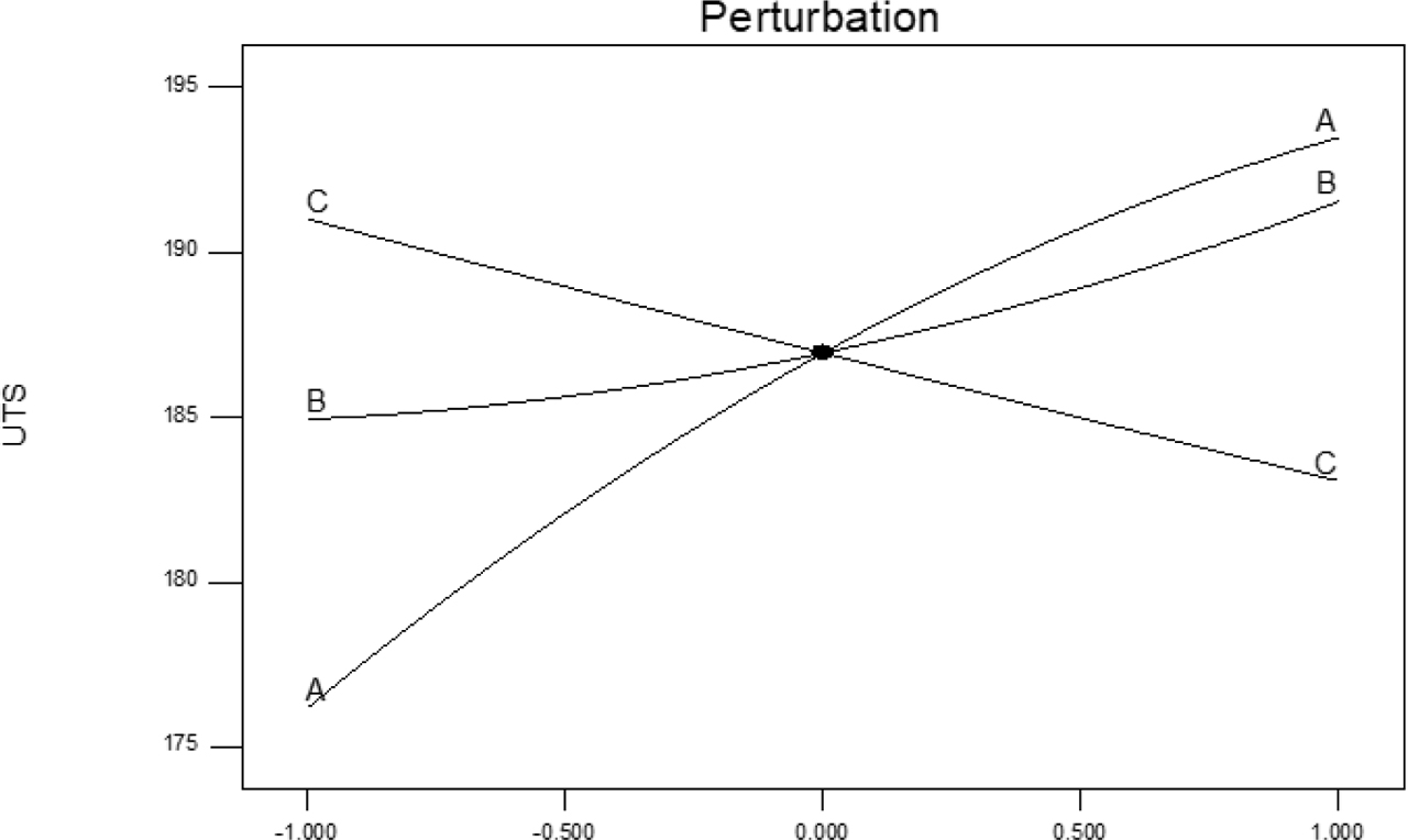
Fig. 6
The influence of UWFSW parameters on the UTS of the UWFSW joint is shown by a perturbation plot
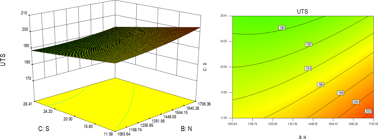
Fig. 7
The influence of N and S on the UTS of the UWFSW joint is represented by contour plots: (A) plot of contour 2D; (B) plot of contour 3D
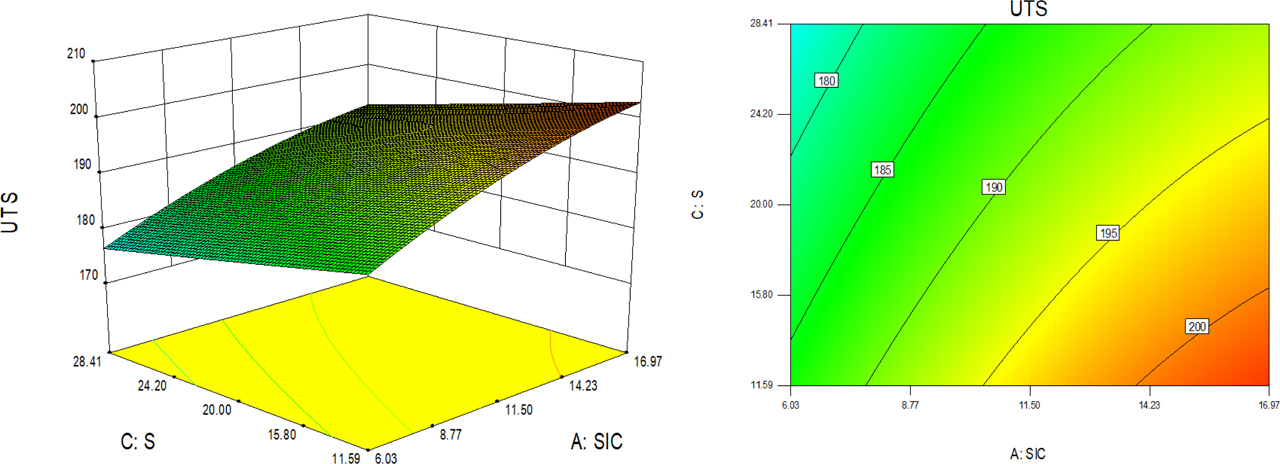
Fig. 8
The influence of SiC and S on the UTS of the UWFSW joint is represented by contour plots: (A) plot of contour 2D; (B) plot of contour 3D
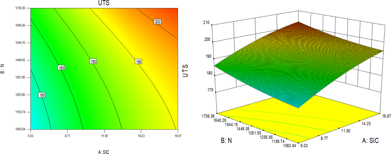
Fig. 9
The influence of N and S on the UTS of the UWFSW joint is represented by contour plots: (A) plot of contour 2D; (B) plot of contour 3D
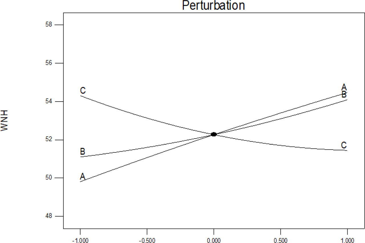
Fig. 10
The influence of UWFSW parameters on the WNH is represented by a perturbation plot
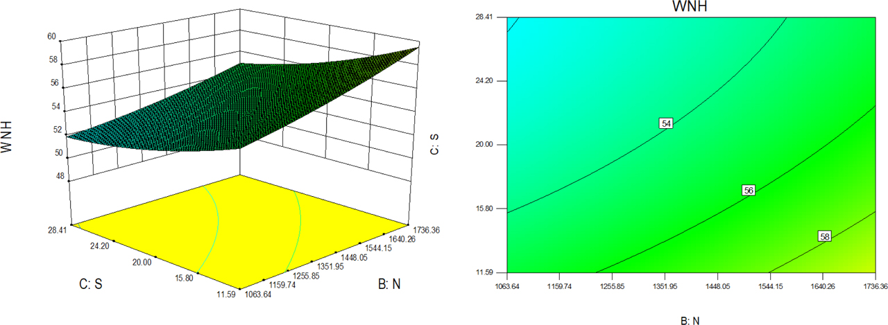
Fig. 11
The influence of N and S on the WNH of the UWFSW joint is represented by contour plots: (A) plot of contour 2D; (B) plot of contour 3D
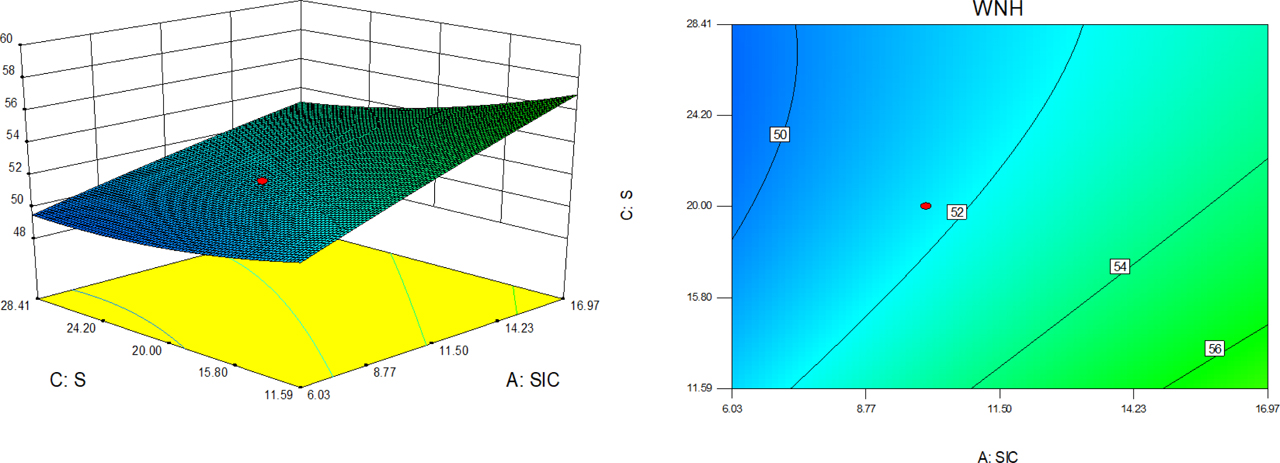
Fig. 12
The influence of SiC and S on the WNH of the UWFSW joint is represented by contour plots: (A) plot of contour 2D; (B) plot of contour 3D
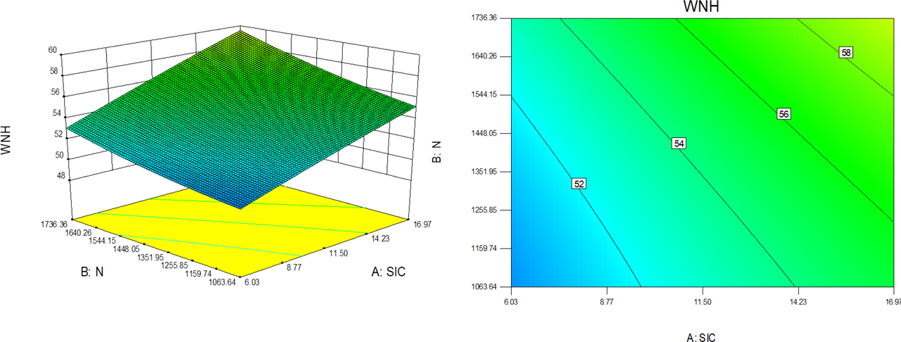
Fig. 13
The influence of N and S on the WNH of the UWFSW joint is represented by contour plots: (A) plot of contour 2D; (B) plot of contour 3D
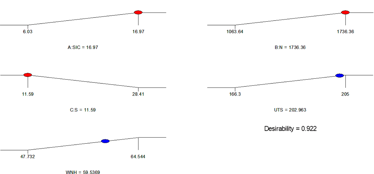
Fig. 14
A graphic that predicts the best UWFSW process parameters
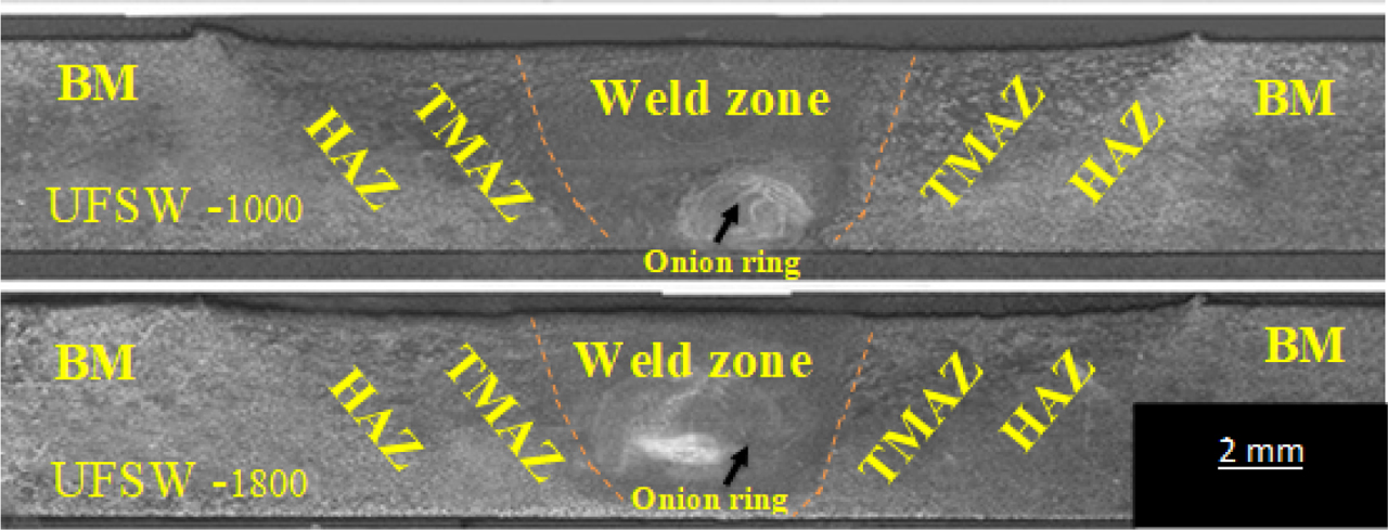
Fig. 15
UWFwelded macrostructure for 6061/18% (A) UWFSW at 1,000 rpm (B) UWFSW at 1,800 rpm SiC composite
Table 7
The outcomes of the experiments as well as the values anticipated by the Design-Expert software for all numbers of runs
| n | UTS | WNH | ||||
|---|---|---|---|---|---|---|
| Actual UTS | Predicted UTS | Error% | Actual WNH | Predicted WNH | Error% | |
| 1 | 205.000 | 204.909 | 0.091 | 64.544 | 59.172 | 5.372 |
| 2 | 196.000 | 192.538 | 3.462 | 55.243 | 55.779 | −0.536 |
| 3 | 190.000 | 184.806 | 5.194 | 52.942 | 53.658 | −0.716 |
| 4 | 200.000 | 200.218 | −0.218 | 55.980 | 57.530 | −1.550 |
| 5 | 190.000 | 187.846 | 2.154 | 53.679 | 54.137 | −0.458 |
| 6 | 180.000 | 180.114 | −0.114 | 51.378 | 52.017 | −0.639 |
| 7 | 190.000 | 195.526 | −5.526 | 55.198 | 55.888 | −0.690 |
| 8 | 185.000 | 183.154 | 1.846 | 52.897 | 52.496 | 0.401 |
| 9 | 174.000 | 175.422 | −1.422 | 50.596 | 50.375 | 0.221 |
| 10 | 202.000 | 200.937 | 1.063 | 56.113 | 57.431 | −1.318 |
| 11 | 186.400 | 188.566 | −2.166 | 53.812 | 54.038 | −0.226 |
| 12 | 174.700 | 180.833 | −6.133 | 51.511 | 51.917 | −0.406 |
| 13 | 195.300 | 196.245 | −0.945 | 54.548 | 55.789 | −1.241 |
| 14 | 183.700 | 183.874 | −0.174 | 52.247 | 52.396 | −0.149 |
| 15 | 172.300 | 176.142 | −3.842 | 49.946 | 50.276 | −0.330 |
| 16 | 193.100 | 191.554 | 1.546 | 53.766 | 54.147 | −0.381 |
| 17 | 180.030 | 179.182 | 0.848 | 51.465 | 50.755 | 0.710 |
| 18 | 170.320 | 171.450 | −1.130 | 49.164 | 48.634 | 0.530 |
| 19 | 196.000 | 196.965 | −0.965 | 56.113 | 55.690 | 0.423 |
| 20 | 185.100 | 184.593 | 0.507 | 52.380 | 52.297 | 0.083 |
| 21 | 176.200 | 176.861 | −0.661 | 50.079 | 50.177 | −0.098 |
| 22 | 191.300 | 192.273 | −0.973 | 53.117 | 54.048 | −0.931 |
| 23 | 184.200 | 179.902 | 4.298 | 50.816 | 50.655 | 0.161 |
| 24 | 171.200 | 172.169 | −0.969 | 48.515 | 48.535 | −0.020 |
| 25 | 187.100 | 187.582 | −0.482 | 52.335 | 52.406 | −0.071 |
| 26 | 181.100 | 175.210 | 5.890 | 50.034 | 49.014 | 1.020 |
| 27 | 166.300 | 167.478 | −1.178 | 47.732 | 46.893 | 0.839 |
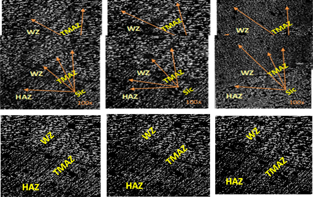
Fig. 16
UWFSW optical microscopic for composite material at 1,000 rpm and 6,061/5%, SiC. (A) At 1,000 rpm and 6,061/10%, SiC. (B) At 1,000 rpm and 6,061/18%, SiC. (C) At 1,800 rpm and 6,061/5%, SiC min. (D) At 1,800 rpm and 6,061/10%, SiC. (E) At 1,800 rpm, SiC (F) and 6,061/18% SiC (G) Microstructure of UWFSW for AL6061 at speed 1,000 rpm (H) Microstructure of UWFSW for AL6061 at speed 1,400 rpm (I) UWFSW for AL6061 at speed 1,800 rpm
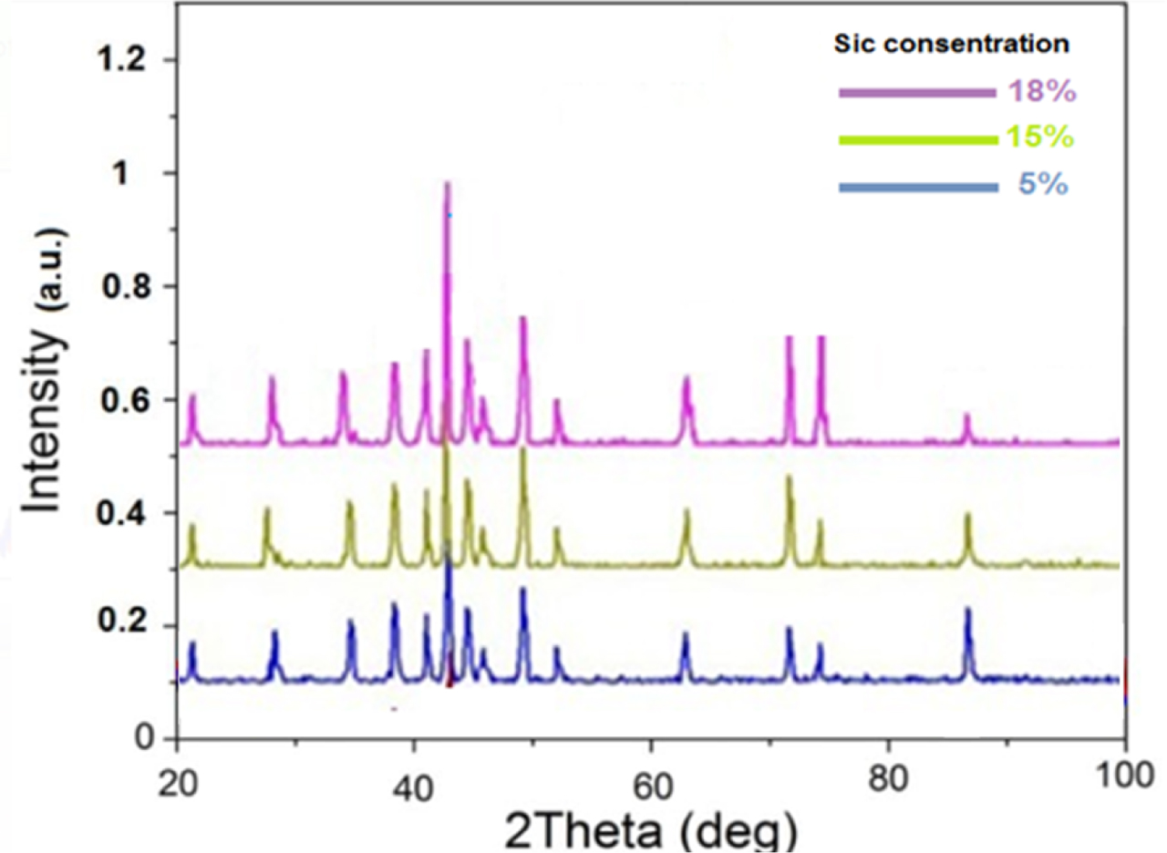
Fig. 17
XRD patterns of AA6061/SiC with different content of SiC particles