
Table 1
Chemical composition, % wt.
| C | Mn | P | Si | Cu | Cr | Ni | Mo | V | Nb | Ti |
|---|---|---|---|---|---|---|---|---|---|---|
| 0.02 | 1.621 | 0.0097 | 0.332 | 0.026 | 0.29 | 0.29 | 0.014 | 0.036 | 0.086 | 0.024 |
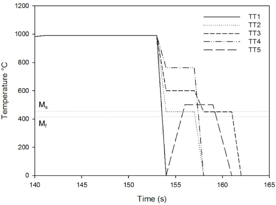
Fig. 1
Schematic diagram of the heat treatments performed on steel. TT, thermal treatment.
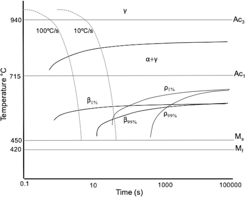
Fig. 2
CCT diagram of the steel studied, calculated by means of the JMat-Pro® program. ρ = pearlite, β = bainita. CCT, continuous cooling transformation.
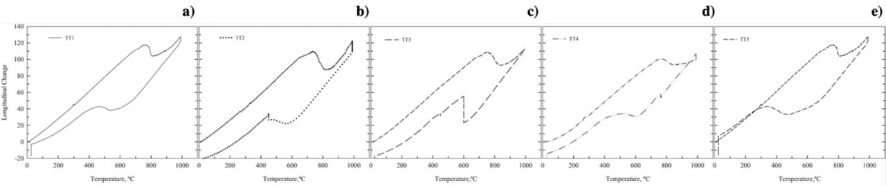
Fig. 3
Dilatometry curves obtained for thermal treatments made in RITA. (A) TT1, (B) TT2, (C) TT3, (D) TT4, and (E) TT5. RITA, rapid induction thermal analysis.
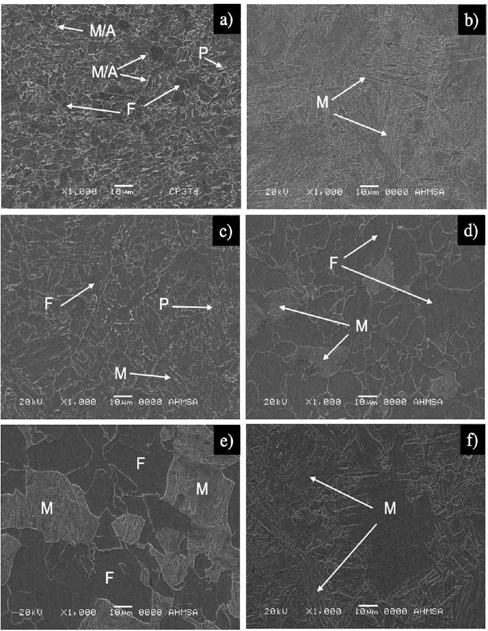
Fig. 4
Photomicrographs obtained by SEM. (A) Untreated steel, (B) TT1, (C) TT2, (D) TT3, (E) TT4, and (F) TT5. F, ferrite M; martensite; MA, martensite/austenite; P, pearlite,; SEM, scanning electron microscopy; TT, thermal treatment.
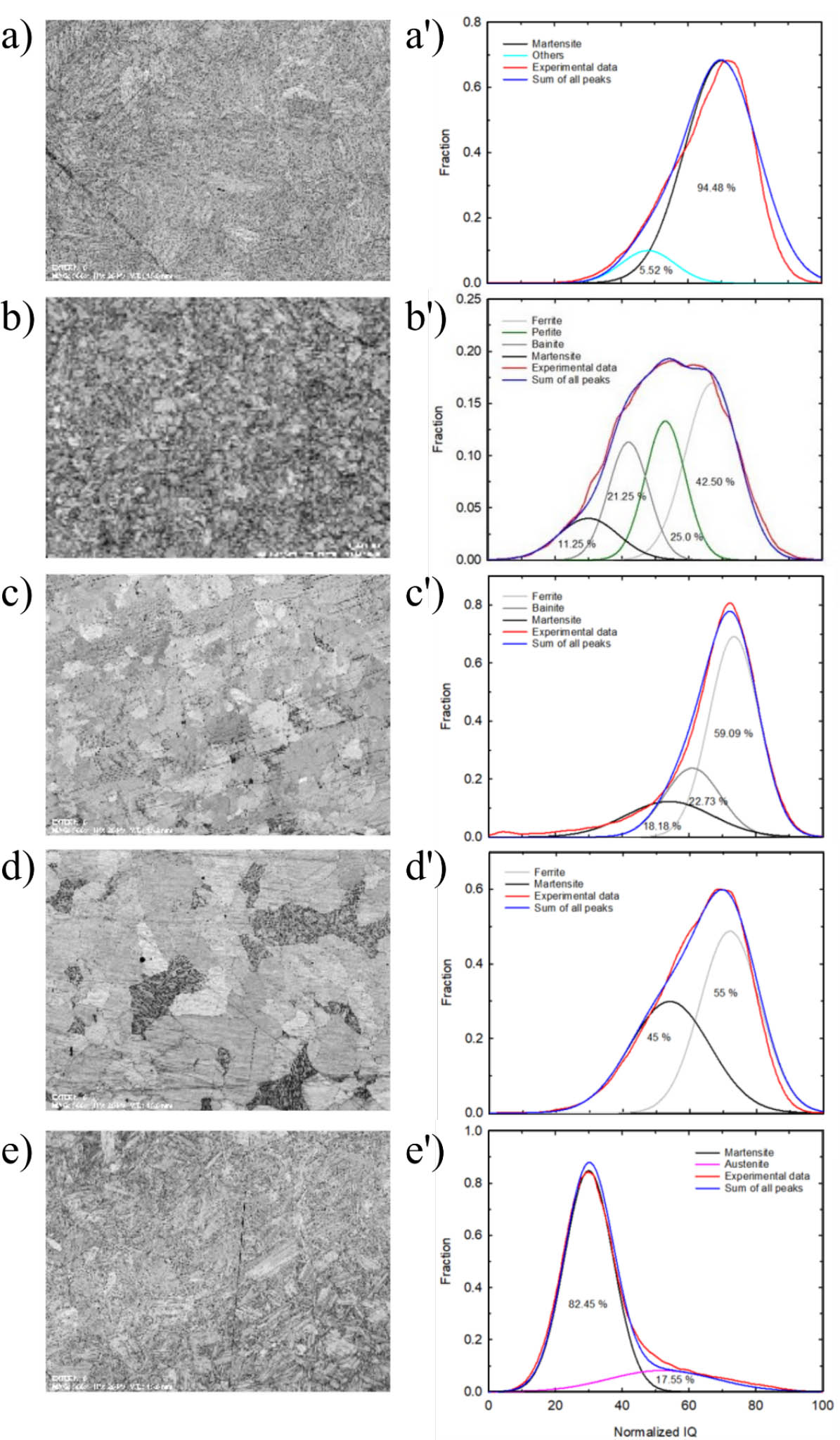
Fig. 5
IQ quality index maps (left) and distribution curves obtained by statistical separation (right) for heat-treated steel: (A) TT1, (B) TT2, (C) TT3, (D) TT4, and (E) TT5. IQ, image quality; TT, thermal treatment.
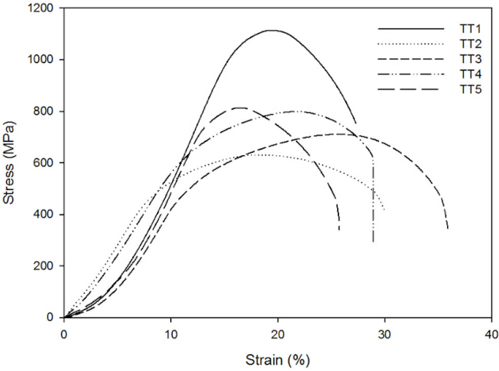
Fig. 6
Averaged stress vs. strain curves obtained for heat-treated steel samples. TT, thermal treatment.
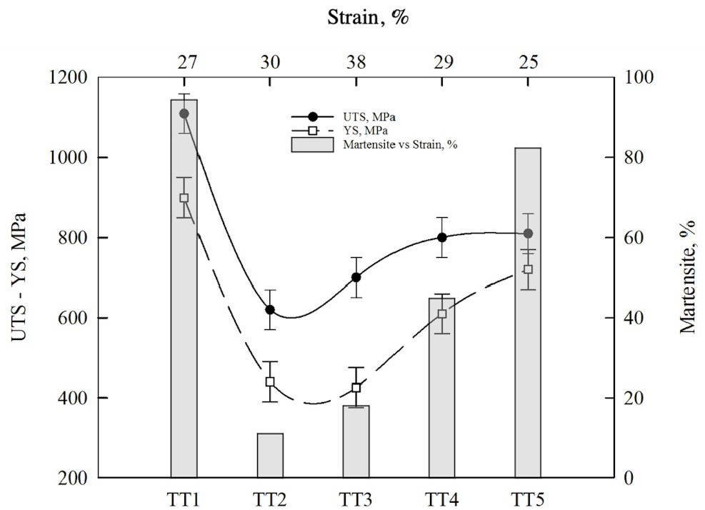
Fig. 7
Effect of heat treatment on mechanical properties and its relationship with the percentage of martensite. TT, thermal treatment; UTS, ultimate tensile strength; YS, yield strength.