
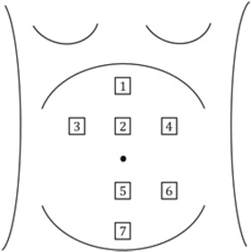
Fig.1
Representation of surface electrode positioning on the abdominal surface.
Table 1
TKEO based algorithm to identify contractions.
| TKEO | based algorithm to identify contractions |
|---|---|
| 1. | The unprocessed EHG signals are obtained. |
| 2. | A running mean (an averaging filter) filter is applied to suppress the short-term noise. |
| 3. | Linear trends or baseline wandering (if observed) is eliminated by detrending the signal. |
| 4. | TKEO and z-score is obtained for the detrended signal. |
| 5. | A Gaussian-smoothing filter is applied to smoothen the signal. |
| 6. | An envelope of the filtered signal is obtained. |
| 7. | Contractions identified. |
Table 2
Algorithm to define threshold to segment contractions identified from the TKEO method.
| Defining threshold to segment contractions from TKEO method | |
|---|---|
| 1. | Obtain the contraction wave from the EHG signals using the TKEO process. |
| 2. | A four-minute window of the RMS signal is chosen. |
| 3. | Hanning window function is used to eliminate the edge effects. |
| 4. | Set Threshold = 1.2*(basal tone + 25% signal range) where Basal tone = mean of 10% of the lowest values. |
| 5. | If the sample value > threshold and is true for > 10 seconds, then |
| 6. | It is identified as a contraction |
| 7. | Else |
| 8. | Move to next sample till the last sample in the four-minute window |
| 9. | Slide the four-minute window by one minute & repeat steps 3 to 8 |
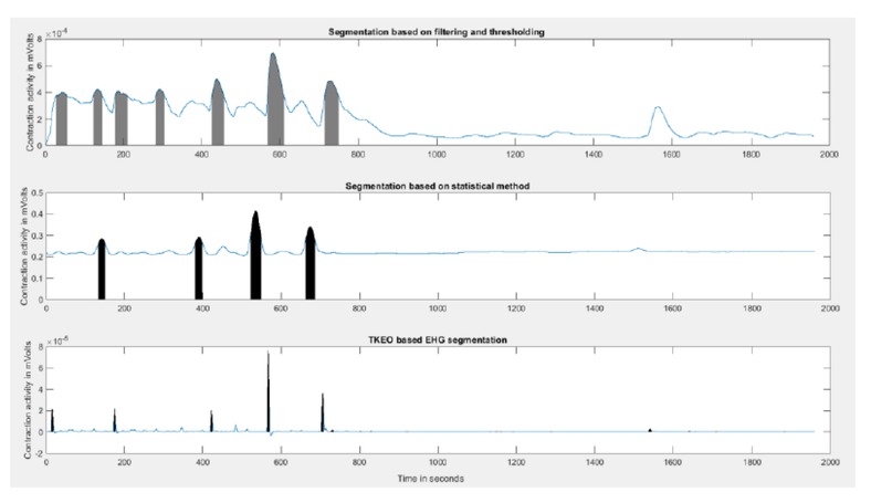
Fig. 2
A comparison of contractions detected using the three methods for the same signal. Top represents the filtering method. Middle represents the statistical method. Bottom represents the TKEO method.
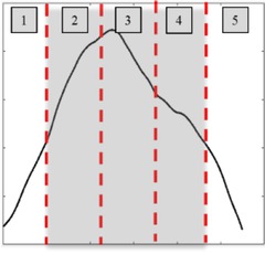
Fig. 3
Five equi-temporal regions of a contraction
Table 3
The algorithm to calculate the dominant region of the contraction.
| 1. | Bipolar signals BPU and BPL representing the electrical activity specific to the upper and lower uterine segments are calculated. |
| 2. | An envelope of the BPU and BPL is obtained by using Hilbert’s transform. |
| 3. | The entire duration of contraction is divided into five equal parts 1 to 5. |
| 4. | The RMS amplitude is calculated for the upper and the lower bipolar signals for regions 2,3 and 4 (RMS-u2, RMS-u3, RMS-u4 and RMS-l2, RMS-l3, RMS-l4) representing the most substantial part of the contraction. |
| 5. | Dominance is calculated for segments 2, 3 & 4 (D2, D3, D4). |
| 6. | The upper uterine segment is dominant if D is positive, and the lower uterine segment is dominant if D is negative. |
| 7. | The dominance for the entire contraction is considered to be the most common pattern of dominance in segments 2, 3, and 4. |
| 8. | End |
Table 4
Transition probabilities of normal progress group.
| States | State 1 | State 2 | State 3 | State 4 | State 5 |
|---|---|---|---|---|---|
| State 1 | 0.692 | 0.263 | 0.400 | 0.500 | 0.385 |
| State 2 | 0.051 | 0.368 | 0.200 | 0.500 | 0.231 |
| State 3 | 0.026 | 0.053 | 0.200 | 0.000 | 0.231 |
| State 4 | 0.051 | 0.105 | 0.000 | 0.000 | 0.154 |
| State 5 | 0.179 | 0.211 | 0.200 | 0.000 | 0.000 |
Table 5
Transition probabilities of arrested/prolonged progress group
| States | State 1 | State 2 | State 3 | State 4 | State 5 |
|---|---|---|---|---|---|
| State 1 | 0.667 | 0.333 | 1.000 | 0.000 | 0.667 |
| State 2 | 0.067 | 0.000 | 0.000 | 0.000 | 0.000 |
| State 3 | 0.067 | 0.000 | 0.000 | 0.000 | 0.000 |
| State 4 | 0.000 | 0.000 | 0.000 | 1.000 | 0.333 |
| State 5 | 0.200 | 0.667 | 0.000 | 0.000 | 0.000 |
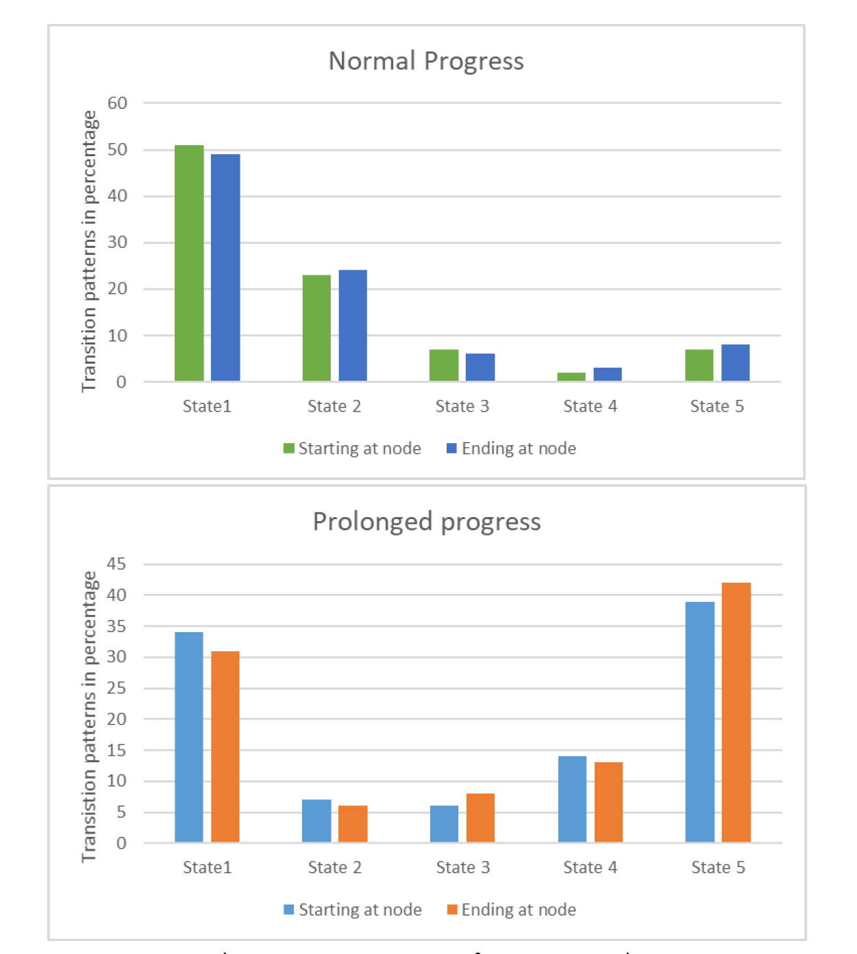
Fig. 4
The transition patterns of contractions between the states represented in percentage
Table 6
Dominant region of the uterus during contractions.
| Feature | Group | Upper uterine segment | Lower uterine segment |
|---|---|---|---|
| Normal progress | 38.94% | 61.05% | |
| Dominance | arrested Prolonged/ progress | 73.58% | 26.41% |
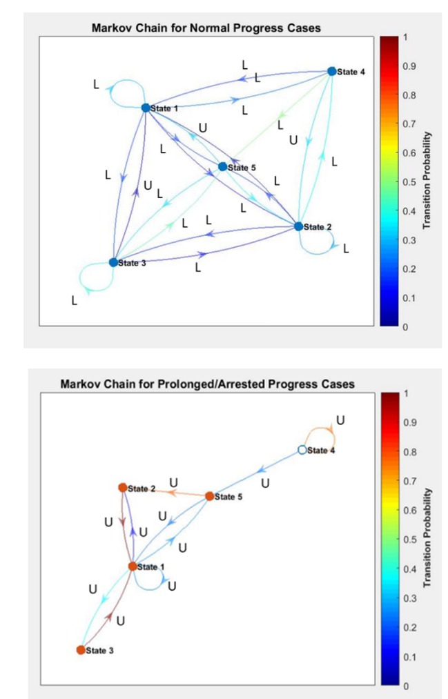
Fig. 5
Representation of the Markov chain correlation coefficients and the dominance of the uterine segment associated with them.
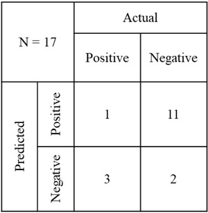
Fig. 6
Confusion matrix of the prediction of the prolonged labor for the test data.