
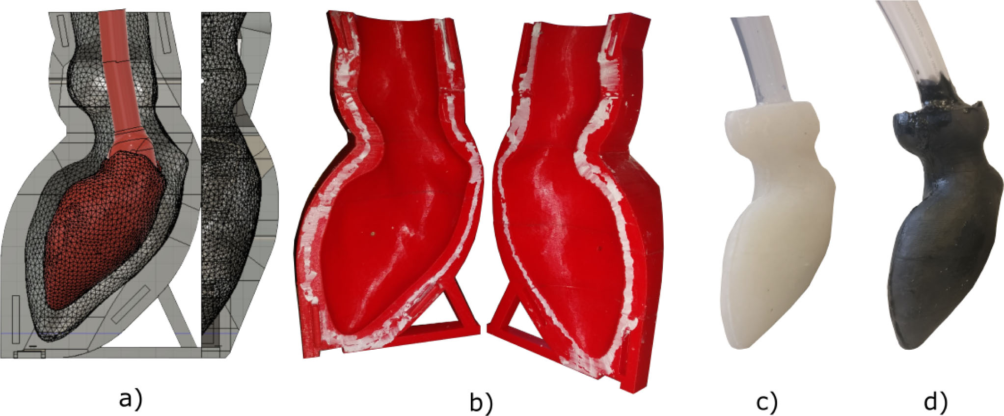
Fig. 1
a) CAD model with the inner wax-/ polyvinylalcohol-core; b) 3D-printed casting molds from polylactide; c) Resulting insulating ventricle from silicone; d) Resulting conductive ventricle from silicone and carbon.
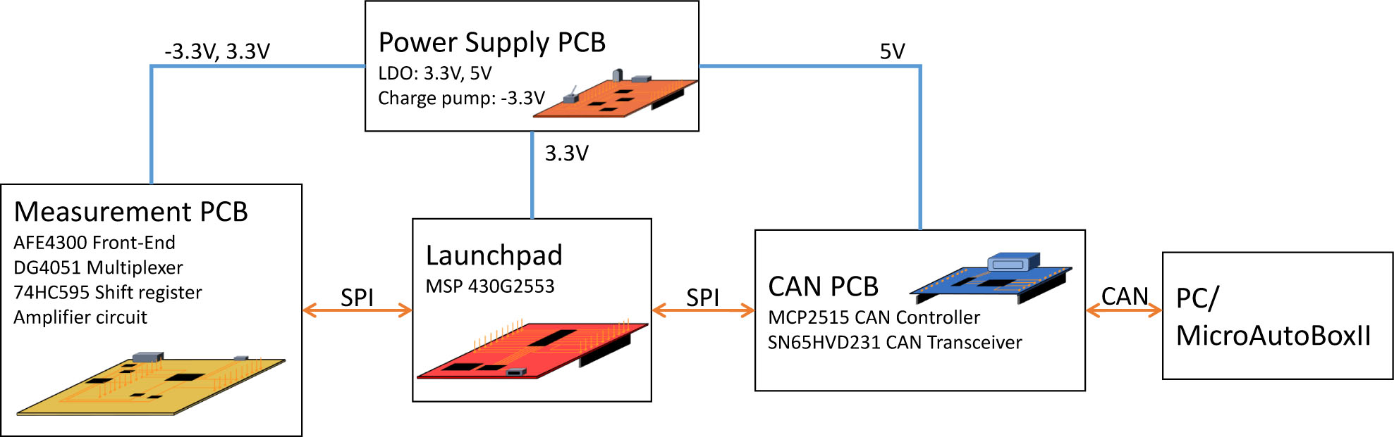
Fig. 2
Schematic overview of the modular layout of the impedance measurement unit.
Tab. 1
Calibration network consisting of four resistances used for the AFE4300.
| R00 | R01 | R10 | R11 |
|---|---|---|---|
| 14,9 Ω | 46,97 Ω | 679 Ω | 995 Ω |
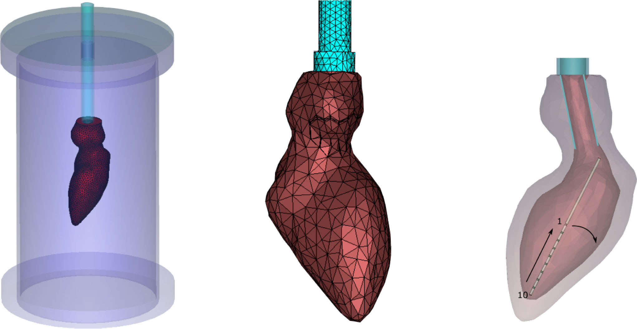
Fig. 3
Left: In silico FE model similar to the in vitro model from CAD files; middle: Mesh view of the FE model; right: Close-up of the ventricle's longitudinal cross-section with the ten-electrode catheter.
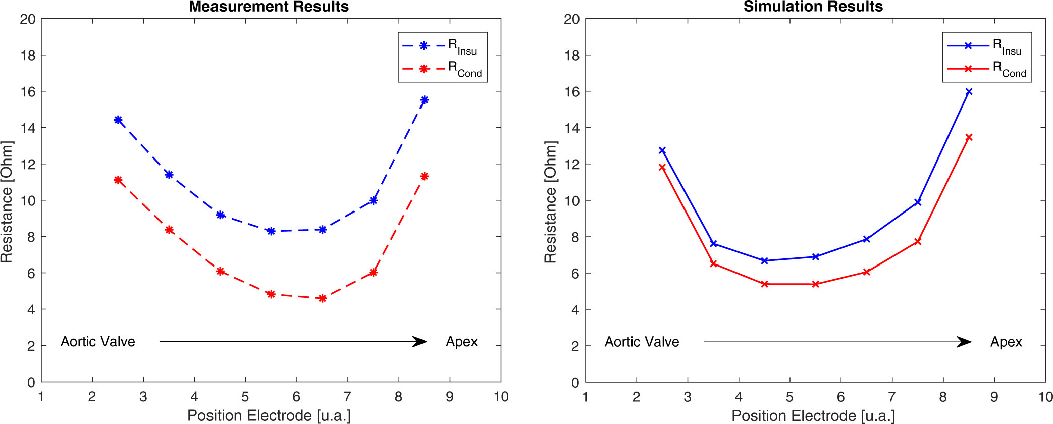
Fig. 4
Left: Measured impedances in the conductive (red) and insulating silicone ventricle (blue) impedance; right: Simulated impedances in the conductive (red) and insulating ventricle (blue).
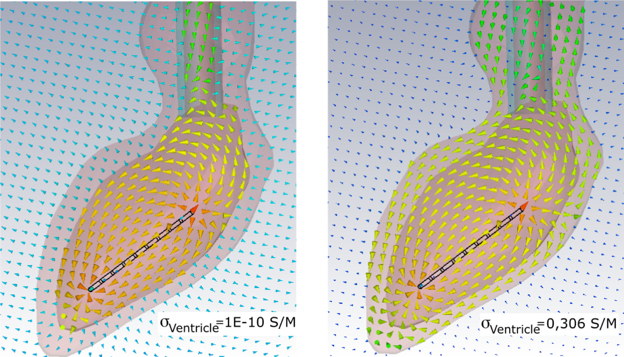
Fig. 5
Close-up of the current paths in the ventricle with insulating properties (left) and conductive properties (right).