
Table 1
Schematic flow of image-based reference EIT.
| Step 1: |
| Defining the filtering method to eliminate the muscle’s conductivity distribution and unexpected noise background |
| Obtain: Equation (4) |
| Step 2: |
| Using voltage data t = 0 as an initial conductivity distribution, selecting the mesh of SAT on the forward problem mesh condition, calculating the fat weighted threshold value |
| Obtain: the fat weighted threshold value |
| Step 3: |
| Applying the filter on equation (4) to experimental data |
| Obtain:σabs and σ |
| Step 4: |
| Using voltage data t = 30, 60, and 90 mins to evaluate the varying water content to obtain the conductivity distribution, applying equation (5) |
| Obtain: σdiff |
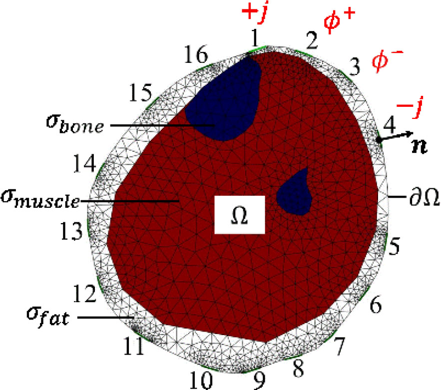
Fig. 1
The FEM forward mesh based on an MRI image. White, red, and blue part indicate SAT layer, muscle, and bone, respectively.
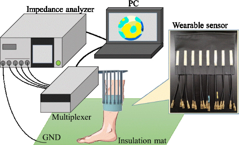
Fig. 2
Experimental setup.

Fig. 3
Schematic diagram of the experimental schedule. After the 3rd measurement (t = 75 min), the subject did exercise to promote varying water contents compared to the original physiological state at the beginning of the experiment.
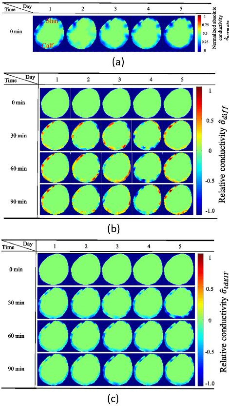
Fig. 4
(a) the normalized absolute conductivity distribution of the right lower leg (viewed from the top) reconstructed by absolute EIT at 1st measurement; These are used as inhomogeneous reference data in (b). Time series of reconstructed relative conductivity distribution using the image-based reference EIT (b) and conventional time difference EIT (c) at 2nd, 3rd, and 4th measurement, respectively.
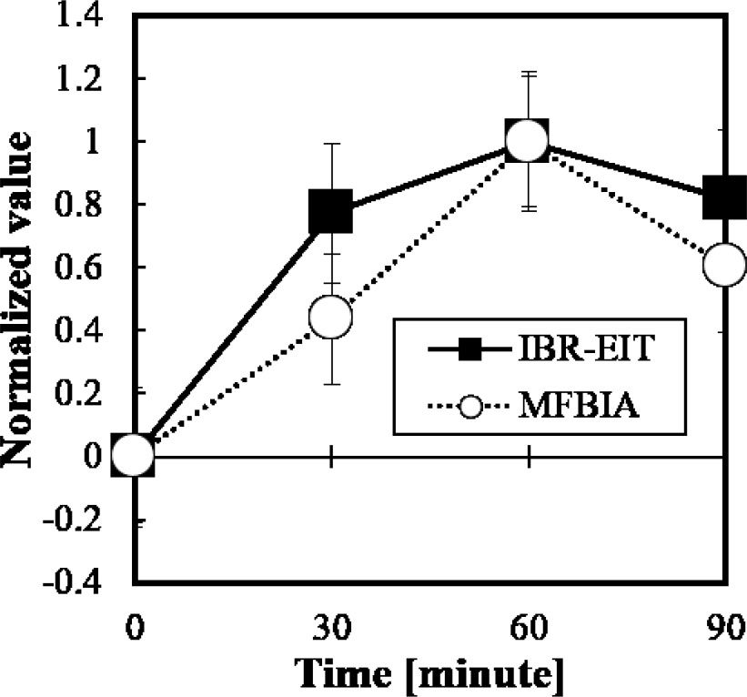
Fig. 5
The normalized temporal variation over segmental conductivity σseg in the predicted subcutaneous layer (white part in Fig.1) and segmental extracellular water volume Vseg in the right leg from image-based reference EIT (IBR-EIT) and MFBIA data, respectively.
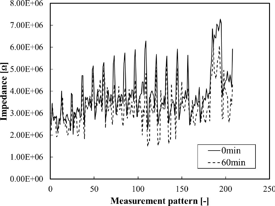
Fig. 6
The magnitude of impedance at 0 min and 60 min on Day 1.