
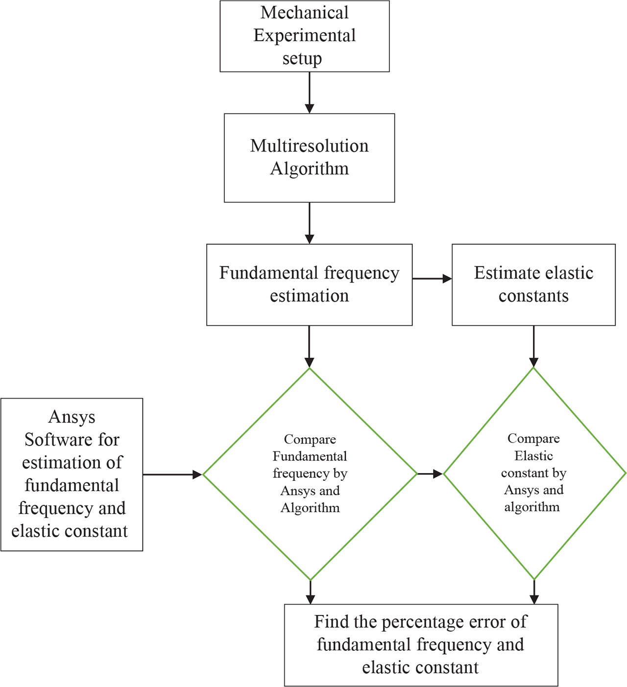
Figure 1:
Flow diagram of the experimental setup.
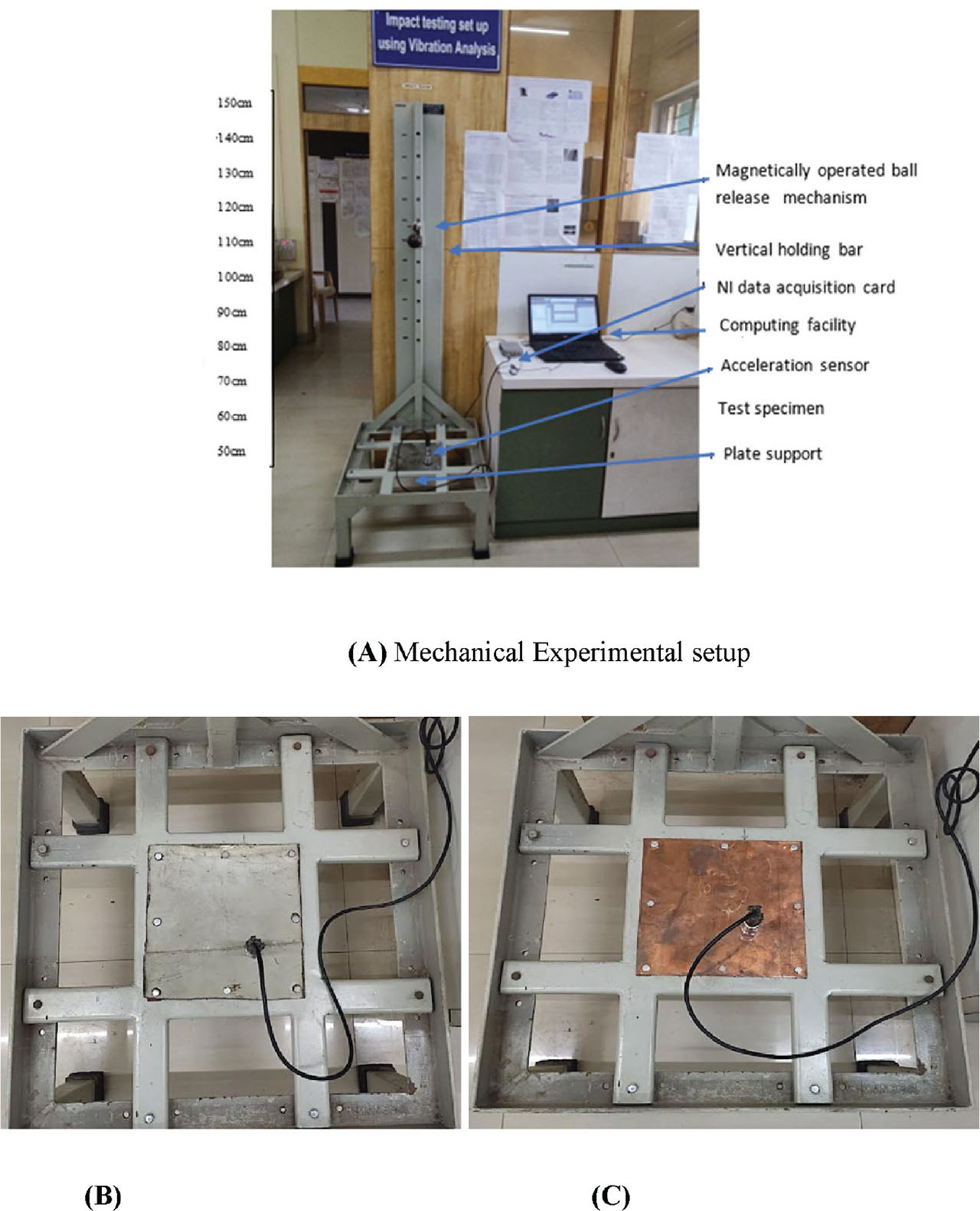
Figure 2:
(A) Experimental setup, (B) SS SA 240 Gr 304 with eight clamps at corners, and (C) copper plate with eight clamps at corner.
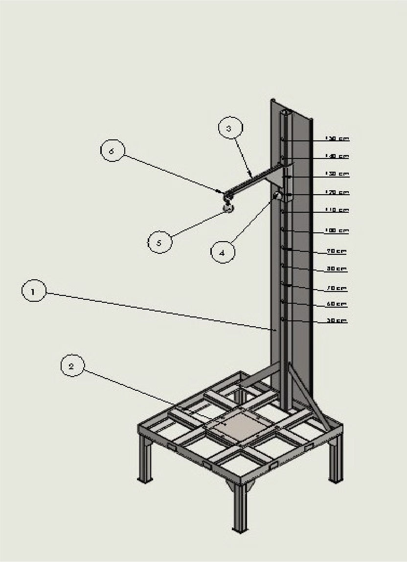
Figure 3:
Free ball impact test setup.
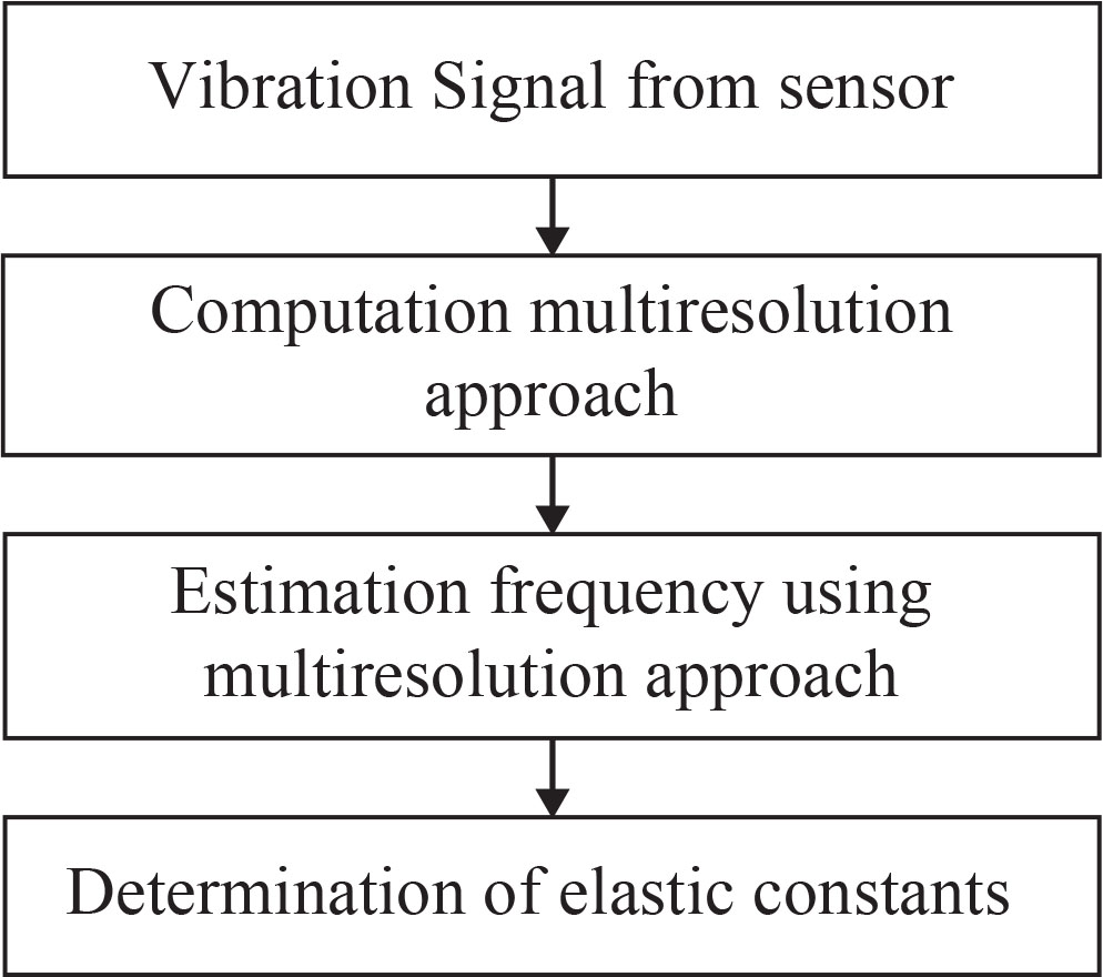
Figure 4:
Proposed techniques.
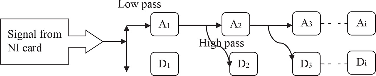
Figure 5:
Decomposition process of a signal using DWT [13]. DWT, discrete wavelet transform.
Table 1:
Average estimated error value of SS specimen sheet.
| SNR input signal (dB) | db4 | coif4 | sym3 | bior2.2 |
|---|---|---|---|---|
| 80 | 8.2710 | 13.3138 | 5.2091 | 6.6665 |
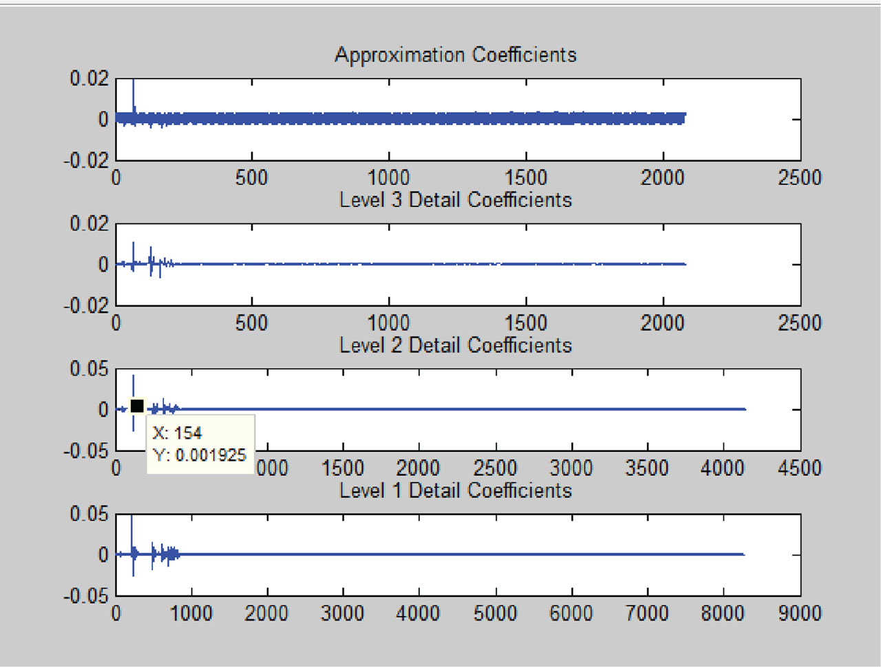
Figure 6:
SS plate Level 2. SS, stainless steel.
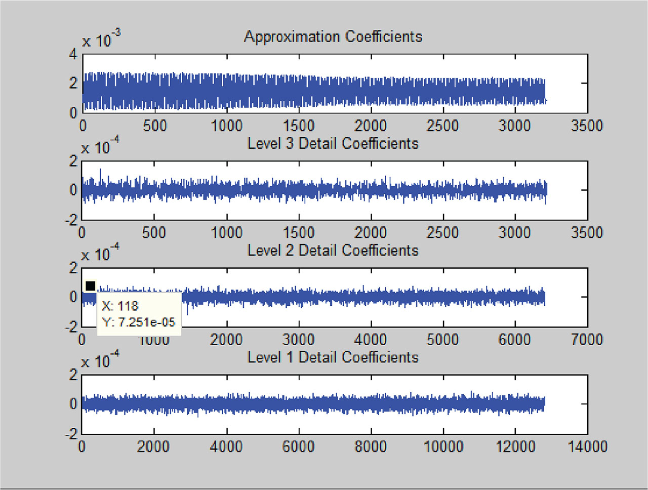
Figure 7:
Copper plate level 2.
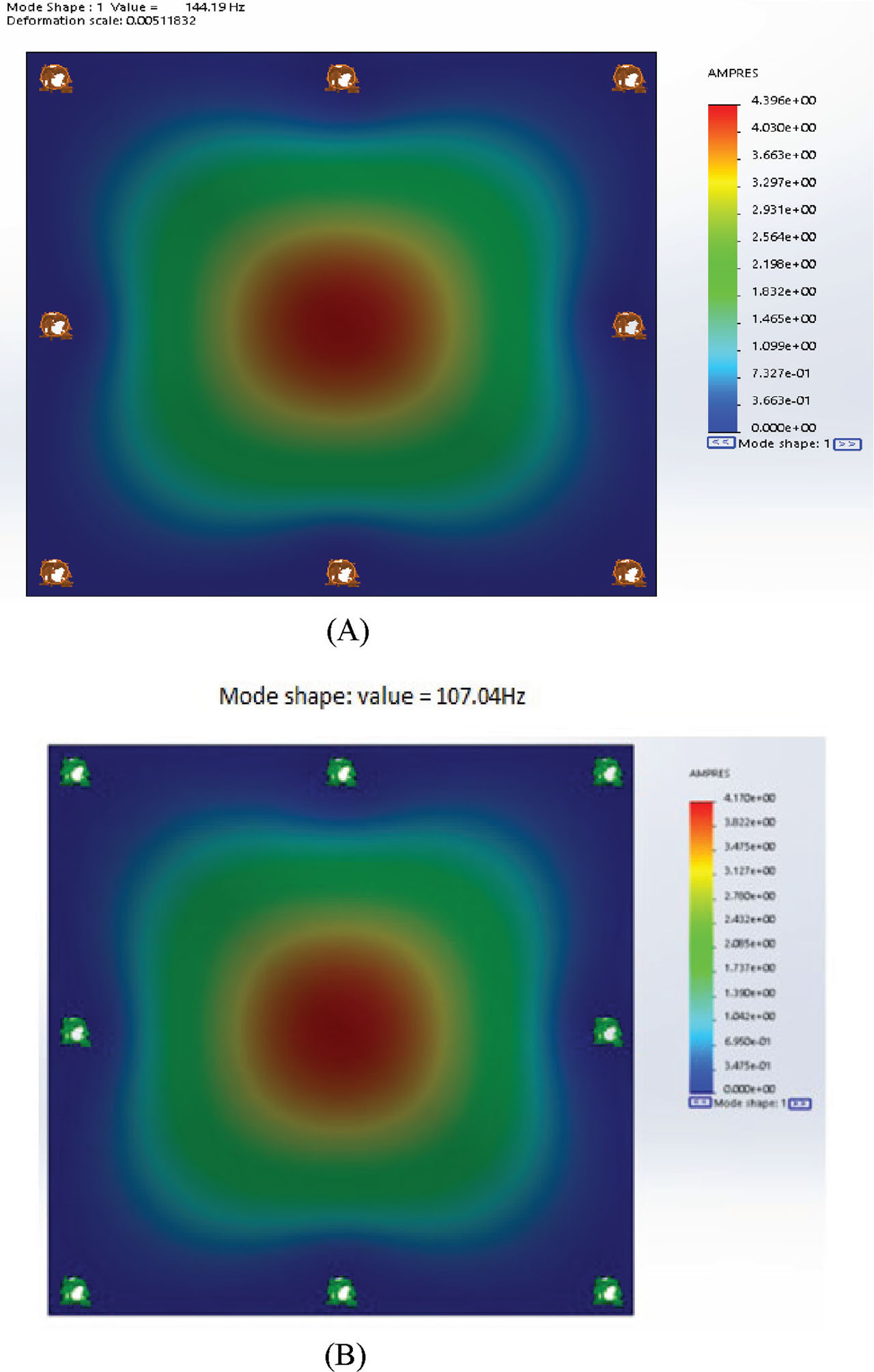
Figure 7:
(A) The SS specimen sheet with dimensions 220 mm × 220 mm × 1.3 mm. Through ANSYS analysis, the fundamental frequency for the first modal vibration is determined to be 144.19 Hz, considering clamping along eight edges. (B) The copper specimen sheet measuring 220 mm × 220 mm × 1 mm. Utilizing ANSYS, the natural frequency of the first modal vibration is identified as 107.04 Hz when considering clamping along eight edges. SS, stainless steel.
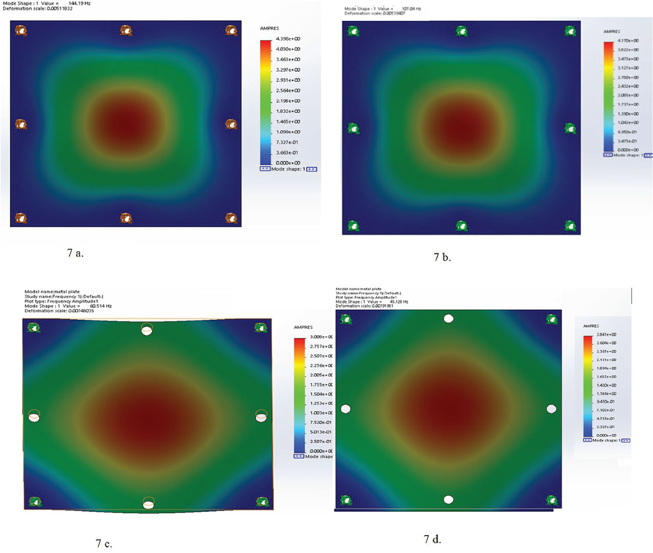
Figure 7:
(A) The stainless steel specimen sheet measuring 220 mm × 220 mm × 1.3 mm. In ANSYS analysis, the first modal natural frequency is found to be 144.19 Hz when considering clamping along eight edges. (B) The copper specimen sheet sized 220 mm × 220 mm × 1 mm, with the ANSYS analysis revealing a first modal natural frequency of 107.04 Hz for eight clamp edges. (C) The stainless steel specimen sheet with the same dimensions (220 mm × 220 mm × 1.3 mm), clamping along four edges. 60.51 Hz. (D) The copper specimen sheet of dimensions 220 mm × 220 mm × 1 mm, similarly clamped along four edges, with ANSYS indicating a first modal natural frequency of 45.12 Hz.
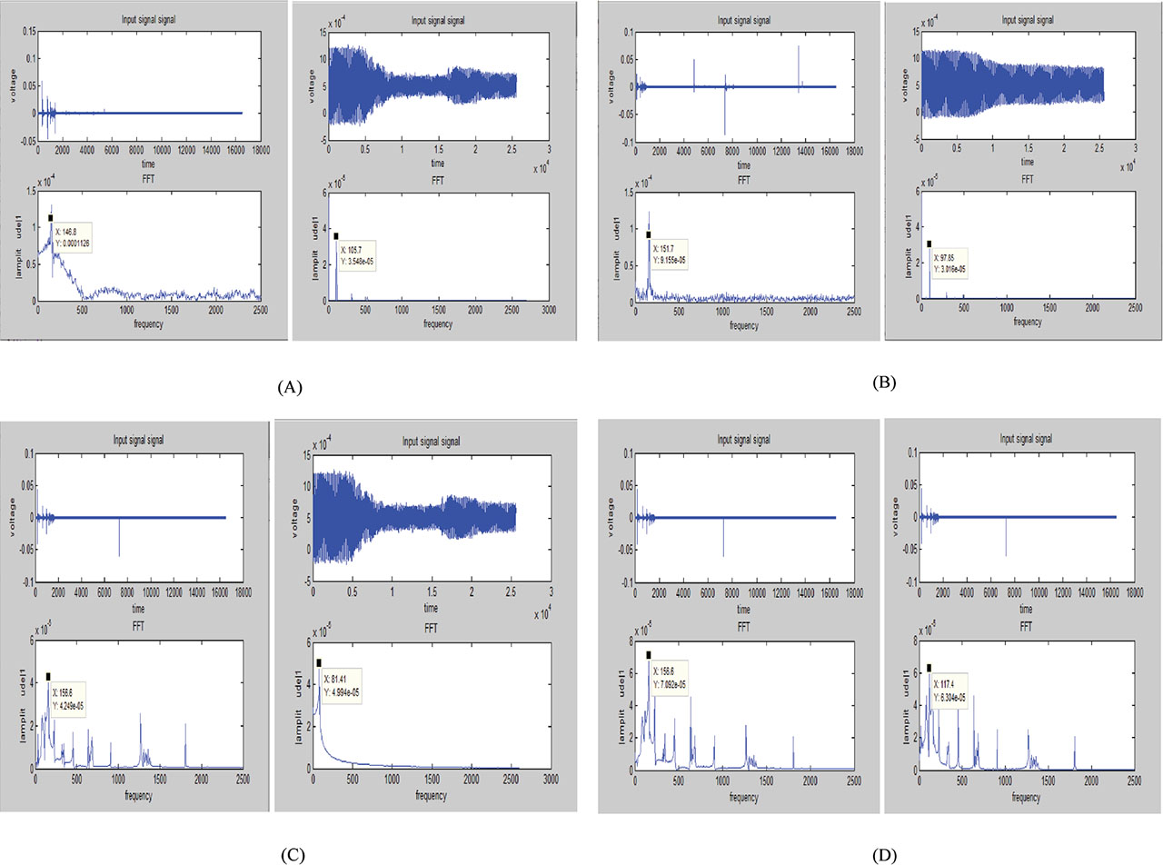
Figure 8:
(A) The power spectral density of SS specimen sheet and copper specimen sheet, both measuring 220 mm × 220 mm × 1.3 mm, obtained using Coiflet wavelets. (B) The power spectral density of SS and Copper specimen sheets is depicted, with the analysis performed using Daubechies Wavelets. (C) A typical power spectral plot for SS and copper specimen sheets, each sized 220 mm × 220 mm × 1.3 mm, employing Symlets wavelets. (D) A similar depiction showcases the typical power spectral plot for SS and Copper specimen sheets, again measuring 220 mm × 220 mm × 1.3 mm, but utilizing BiorSplines wavelets. SS, stainless steel.
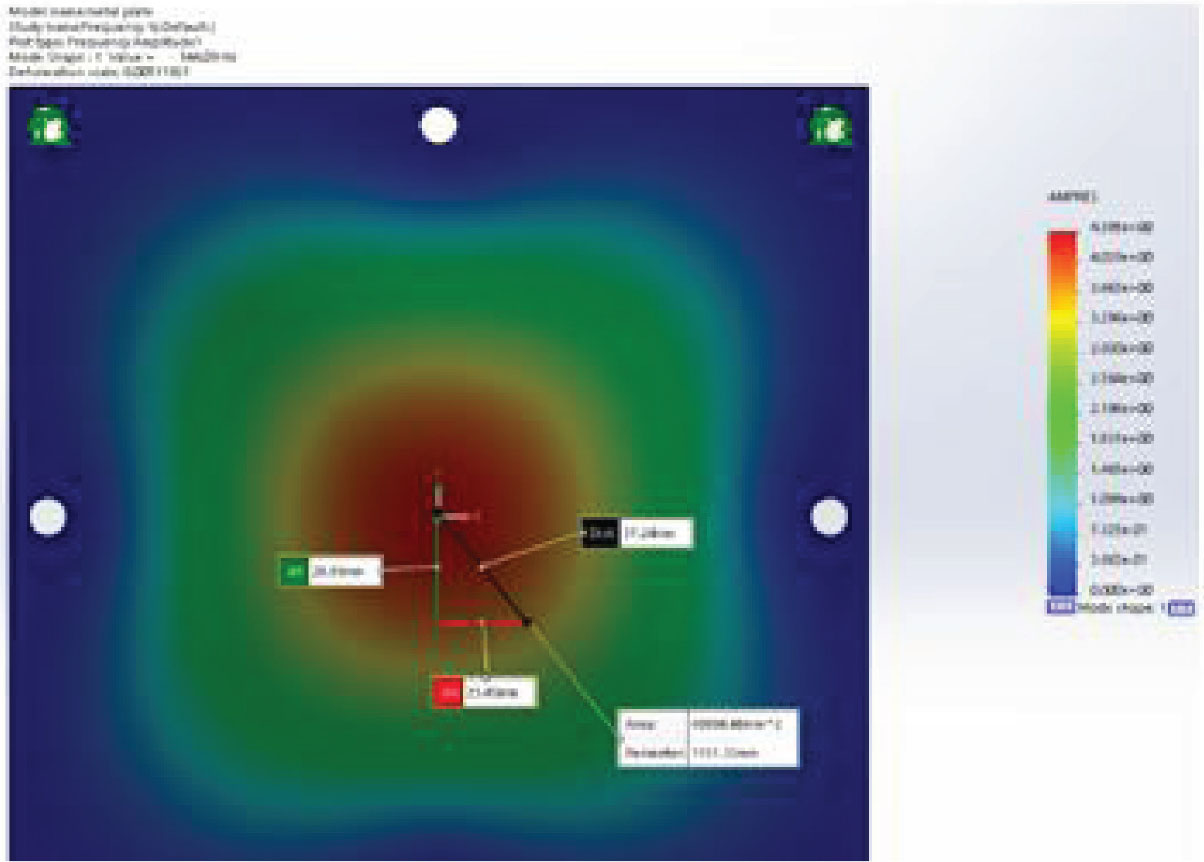
Figure 10:
Location of the acceleration sensor on specimen sheets, 37.24 mm from center.
Table 2:
Average estimated error value of copper specimen sheet.
| Sr. no. | SS specimen plate | Copper specimen plate | |||||||
|---|---|---|---|---|---|---|---|---|---|
| Height of impact in cm | Frequency obtained by FEM (ANSYS software) | Estimated frequency using proposed method | Error (%) | Average error (%) | Frequency obtained by FEM (ANSYS software) | Estimated frequency using proposed method | Error (%) | Average error (%) | |
| 1 | 50 | 144.19 | 146.60 | 1.64 | 1.30% | 107.04 | 105.7 | 1.26 | 1.18% |
| 2 | 70 | 146.02 | 1.25 | 105.8 | 1.17 | ||||
| 3 | 90 | 146.80 | 1.77 | 105.6 | 1.36 | ||||
| 4 | 110 | 145.60 | 0.96 | 105.4 | 1.55 | ||||
| 5 | 130 | 145.80 | 1.10 | 106.2 | 0.80 | ||||
| 6 | 150 | 145.80 | 1.10 | 106.0 | 0.98 | ||||
| Average frequency and error | 146.10 | 1.30 | 105.78 | 1.18 | |||||
Table 3:
Elastic constant for SS specimen sheet.
| Sr no. | SS specimen plate | Copper specwimen plate | |||||||
|---|---|---|---|---|---|---|---|---|---|
| Height of impact in cm | Frequency obtained by FEM (ANSYS software) | Estimated frequency using proposed method | Error (%) | Average error (%) | Frequency obtained by FEM (ANSYS software) | Estimated frequency using proposed method | Error (%) | Average error (%) | |
| 1 | 50 | 144.19 | 146.60 | 1.64 | 1.30% | 107.04 | 105.7 | 1.26 | 1.18% |
| 2 | 70 | 146.02 | 1.25 | 105.8 | 1.17 | ||||
| 3 | 90 | 146.80 | 1.77 | 105.6 | 1.36 | ||||
| 4 | 110 | 145.60 | 0.96 | 105.4 | 1.55 | ||||
| 5 | 130 | 145.80 | 1.10 | 106.2 | 0.80 | ||||
| 6 | 150 | 145.80 | 1.10 | 106.0 | 0.98 | ||||
| Average frequency and error | 146.10 | 1.30 | 105.78 | 1.18 | |||||
Table 4:
Different wavelet estimated frequency and average error for specimen sheets of SS and copper with dimensions 220 mm × 220 mm × 1.3 mm and 220 mm × 220 mm × 1 mm using 200 g ball
| Name of wavelet family | SS specimen plate | Copper specimen plate | ||
|---|---|---|---|---|
| Frequency obtained by FEM (ANSYS software) | Estimated frequency using proposed method | Frequency obtained by FEM (ANSYS software) | Estimated frequency using proposed method | |
| Daubechies wavelets | 144.19 | 151.7 | 107.04 | 97.80 |
| Coiflet wavelet | 146.10 | 105.7 | ||
| Symlets wavelet | 156.6 | 81.41 | ||
| BiorSplines wavelet | 156.8 | 117.6 | ||