
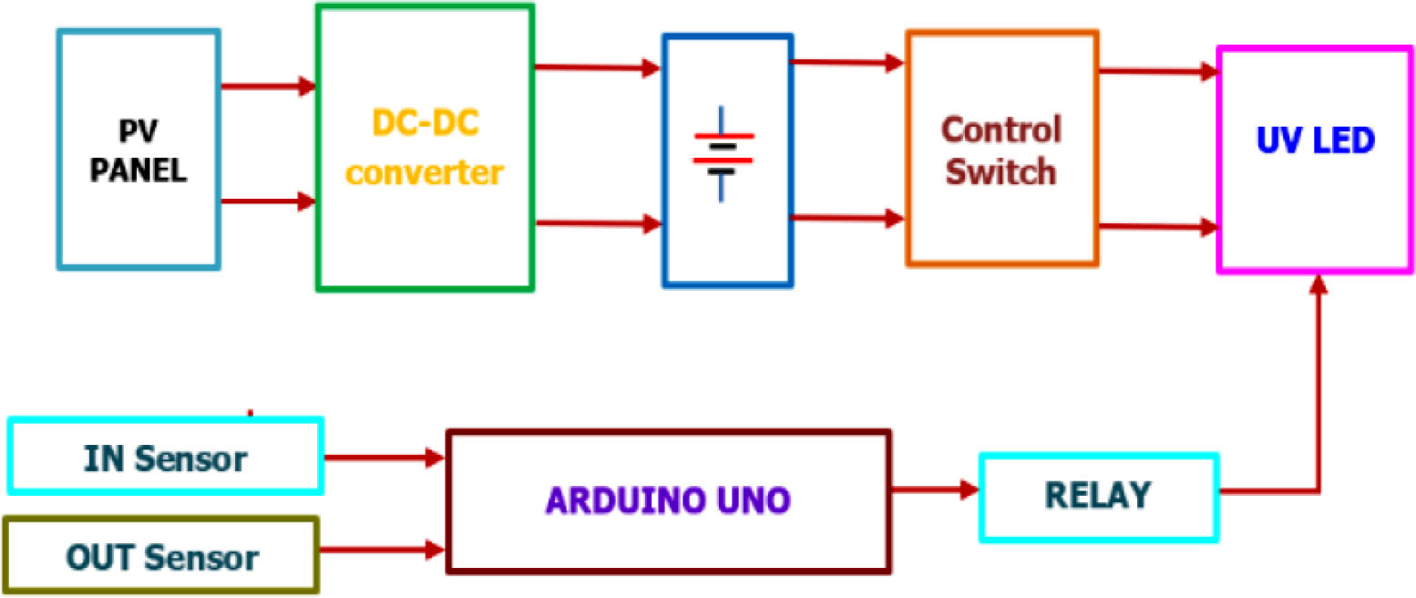
Figure 1:
Block diagram of UV LED with sensor.
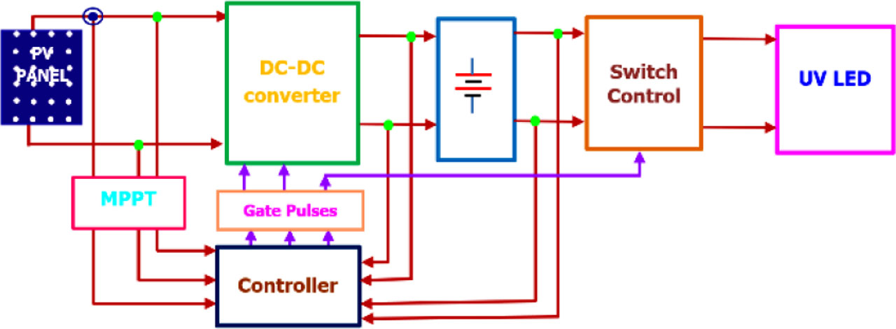
Figure 2:
Block diagram of UV LED lamp with controller.
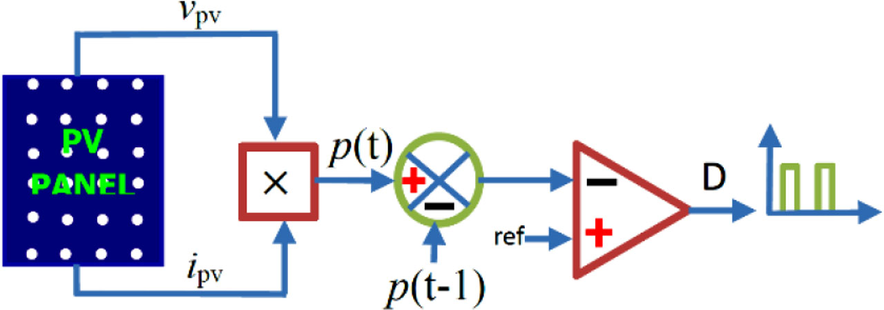
Figure 3:
Functional block diagram of P&O method. P&O, perturb-and-observe.
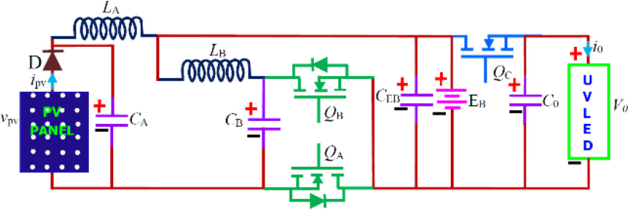
Figure 4:
Proposed converter circuit.
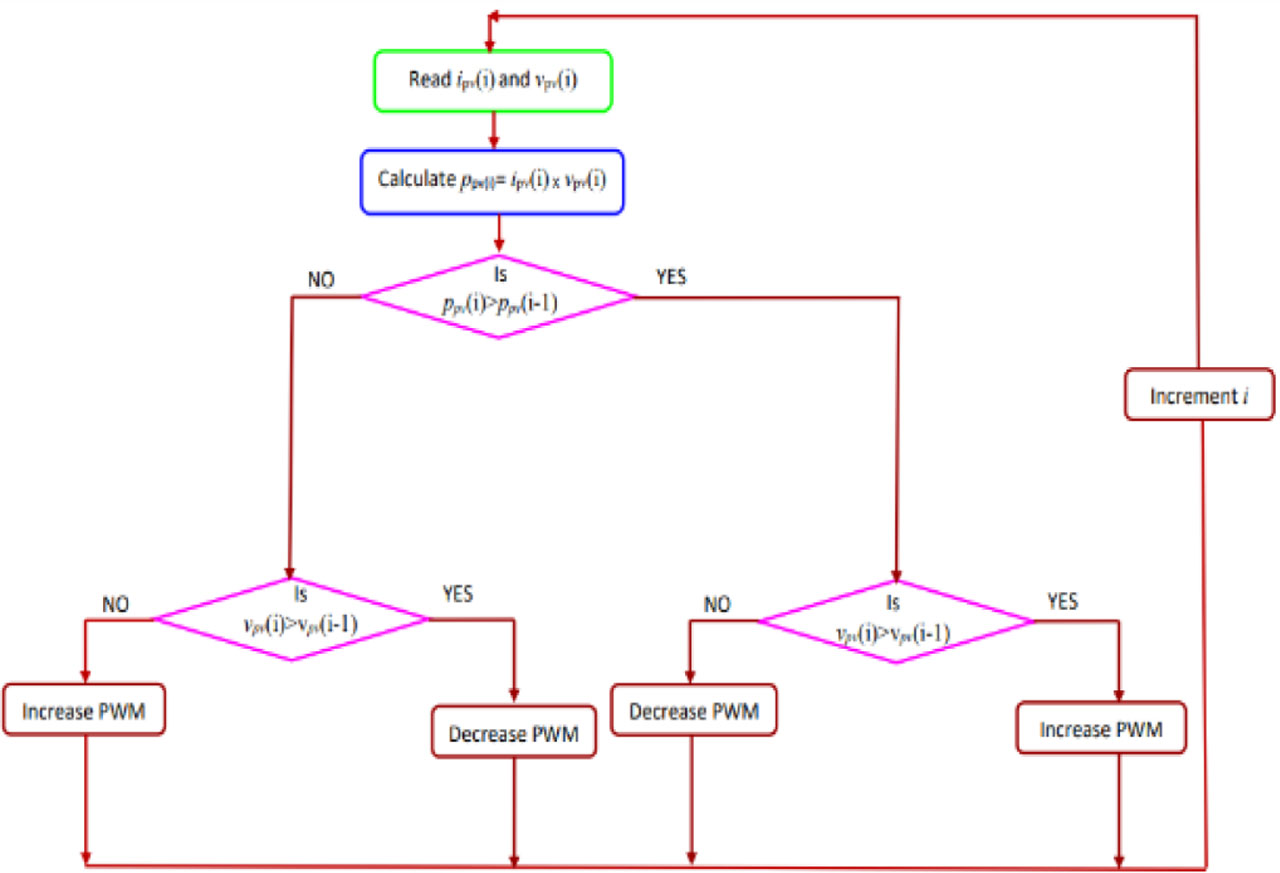
Figure 5:
MPPT algorithm. MPPT, maximum power point tracking.
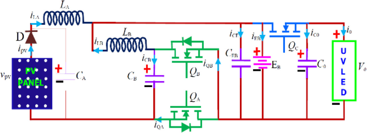
Figure 6:
Equivalent circuit for step-down mode.
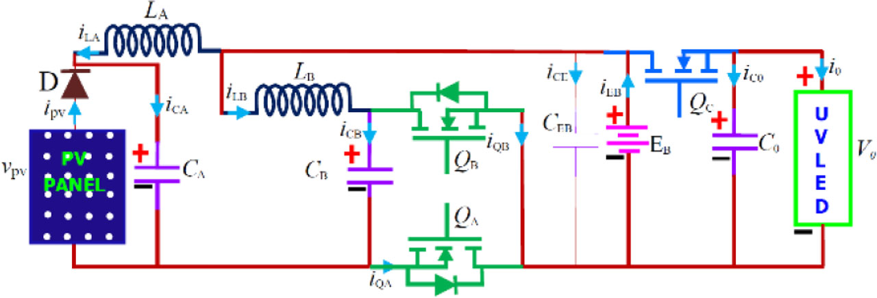
Figure 7:
Equivalent circuit for step-up mode.
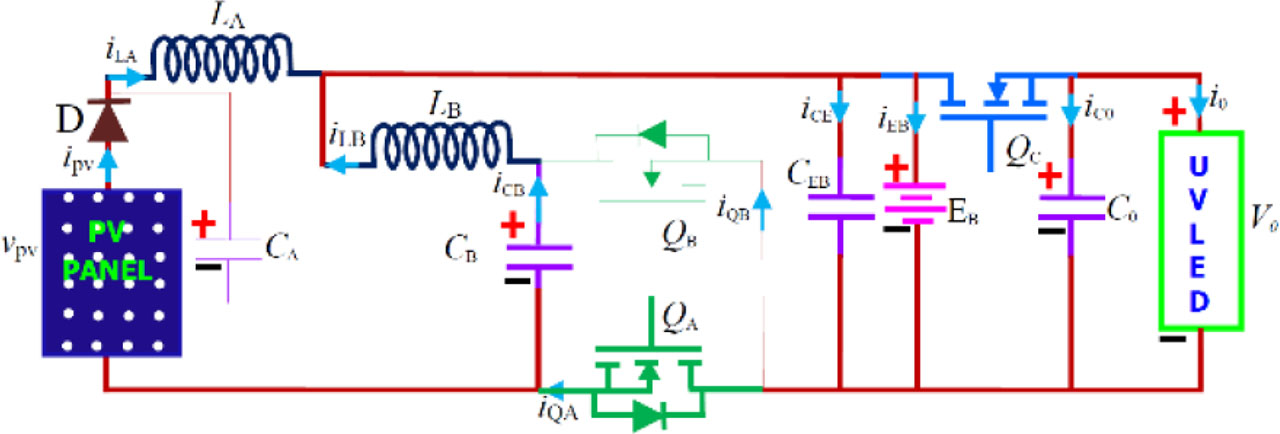
Figure 8:
Step-down mode 1.
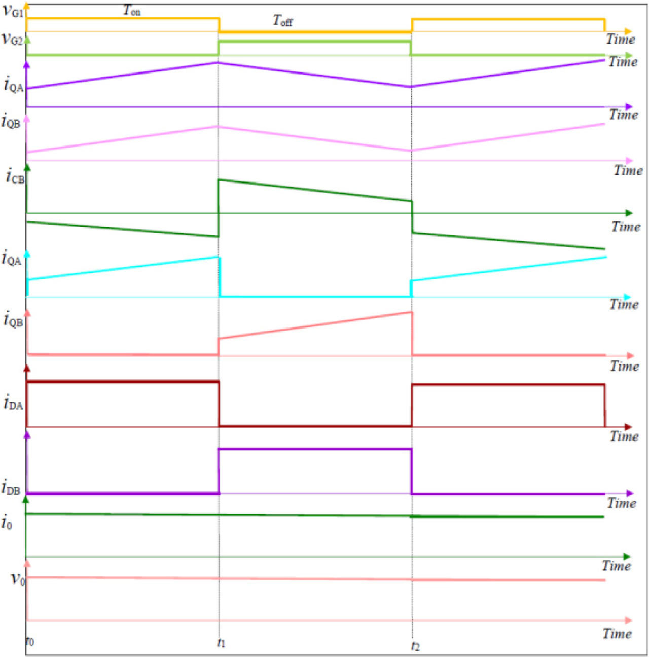
Figure 9:
Waveform for step down.
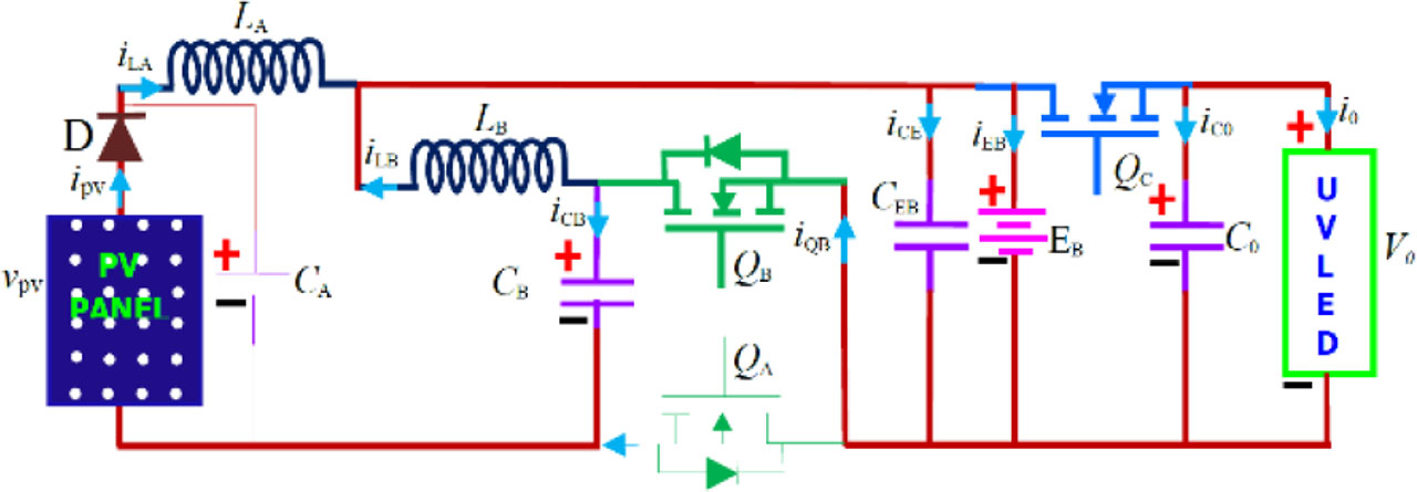
Figure 10:
Step-down mode 2.

Figure 11:
Step-up mode 1.
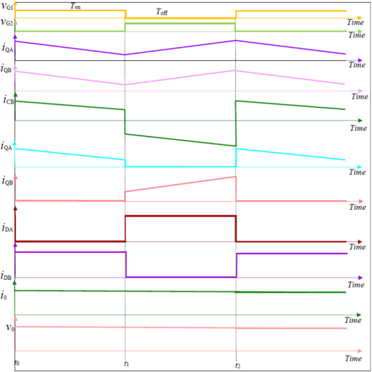
Figure 12:
Waveform for step-up operation.
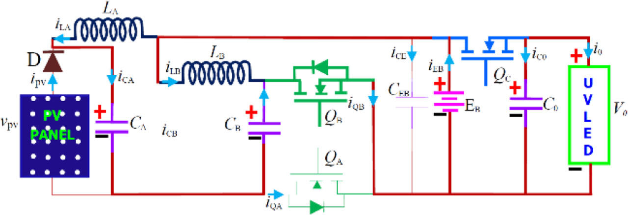
Figure 13:
Step-up mode 2.
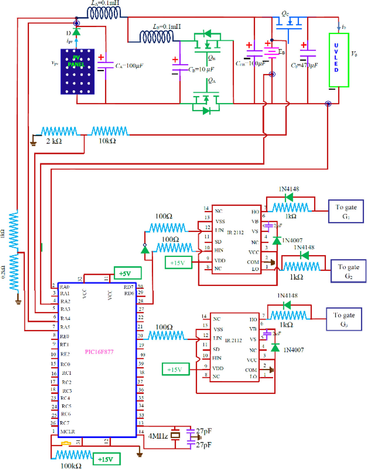
Figure 14:
Proposed UVC sterilizer lamp circuit.
| S. No. | Component | Value |
|---|---|---|
| 1 | Inductor LA | 0.1 mH |
| 2 | Inductor LB | 0.1 mH |
| 3 | Capacitor CA | 100 μC |
| 4 | Capacitor CB | 10 μC |
| 5 | Capacitor CEB | 100 μC |
| 6 | Capacitor C0 | 470 μC |
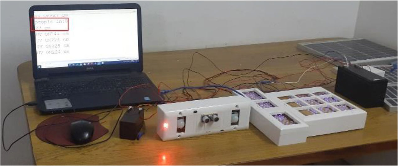
Figure 15:
UV array ON condition.
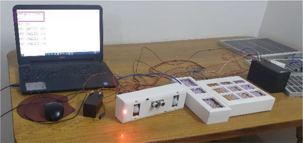
Figure 16:
UV array ON condition.
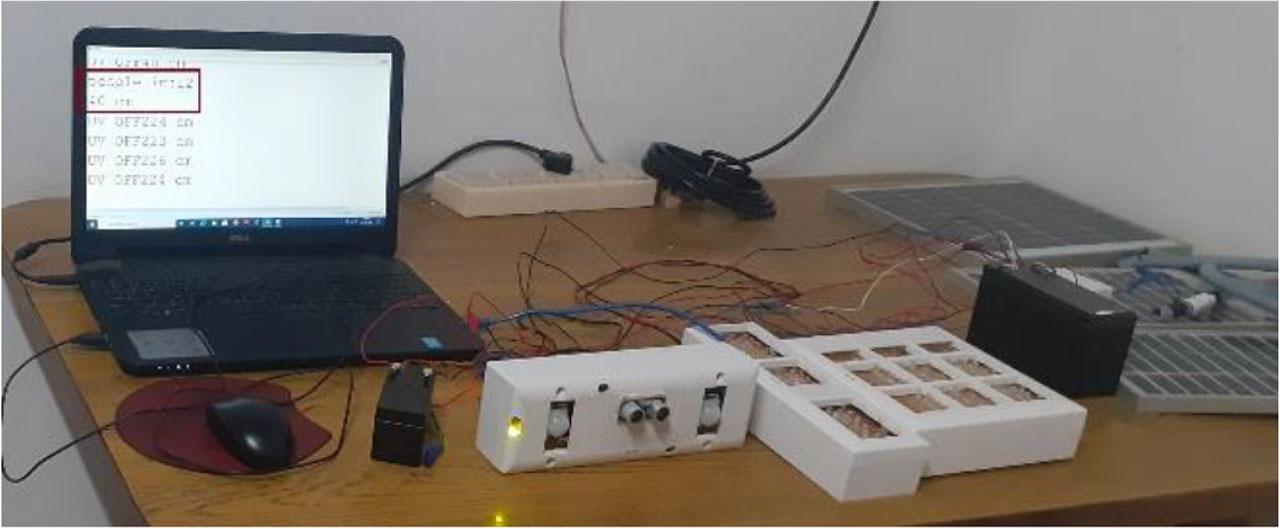
Figure 17:
UV array OFF condition.
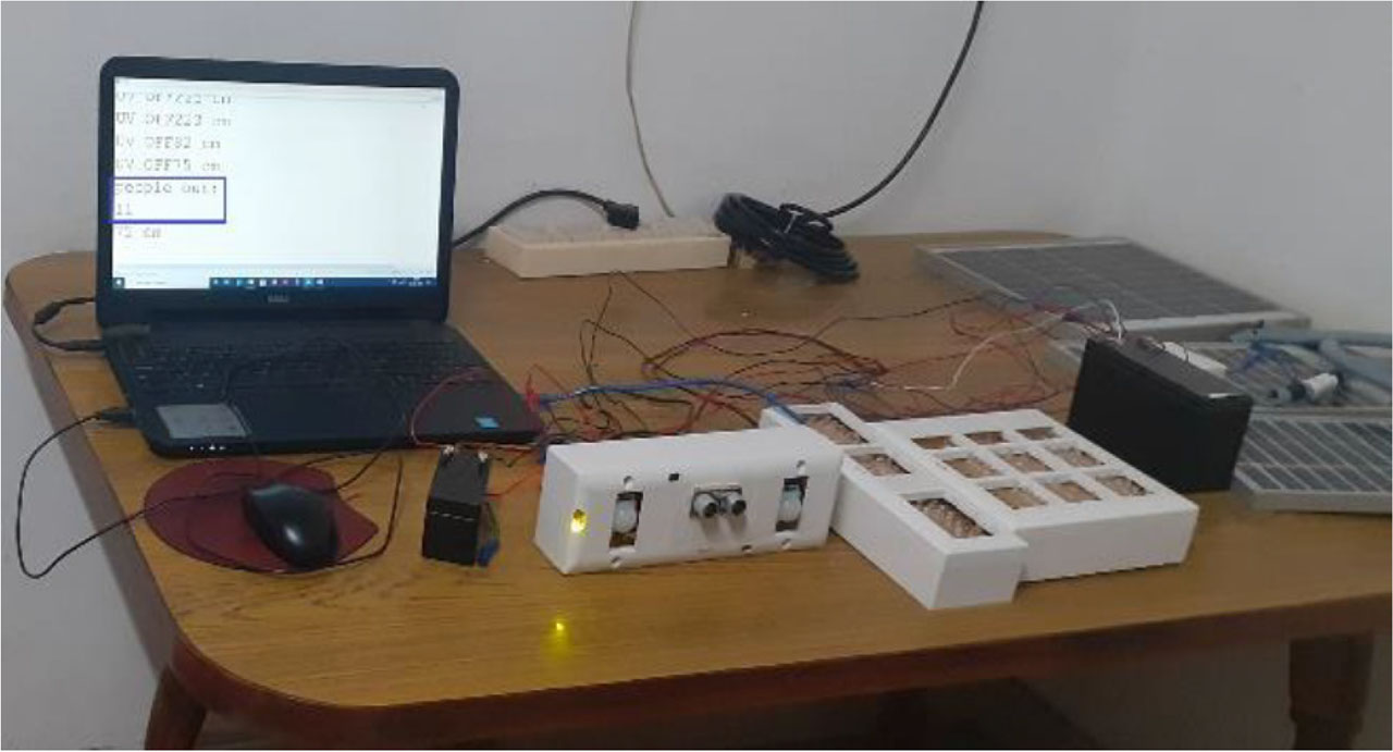
Figure 18:
UV array OFF condition.
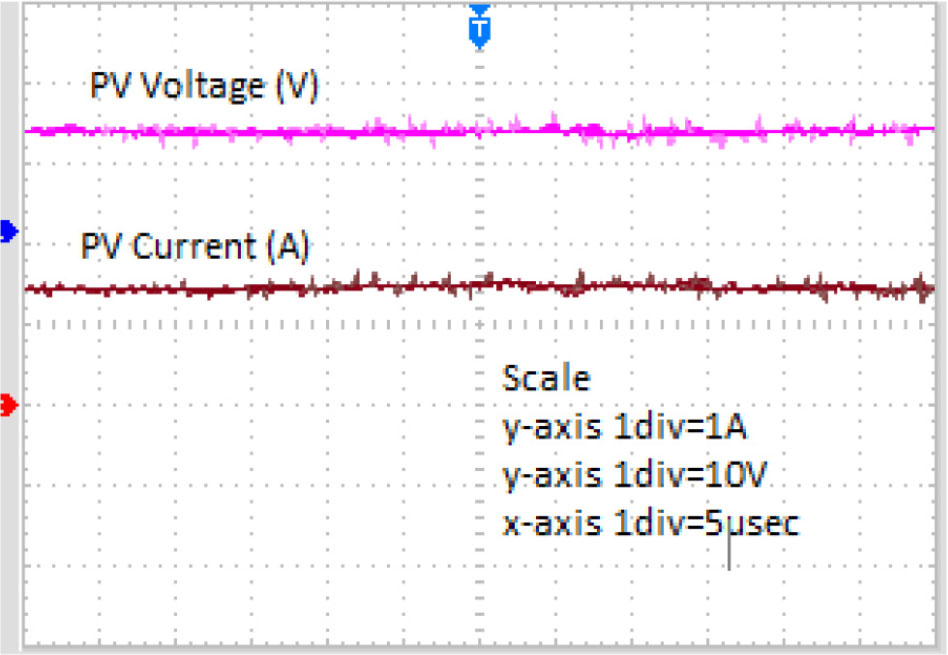
Figure 19:
PV voltage and PV current.
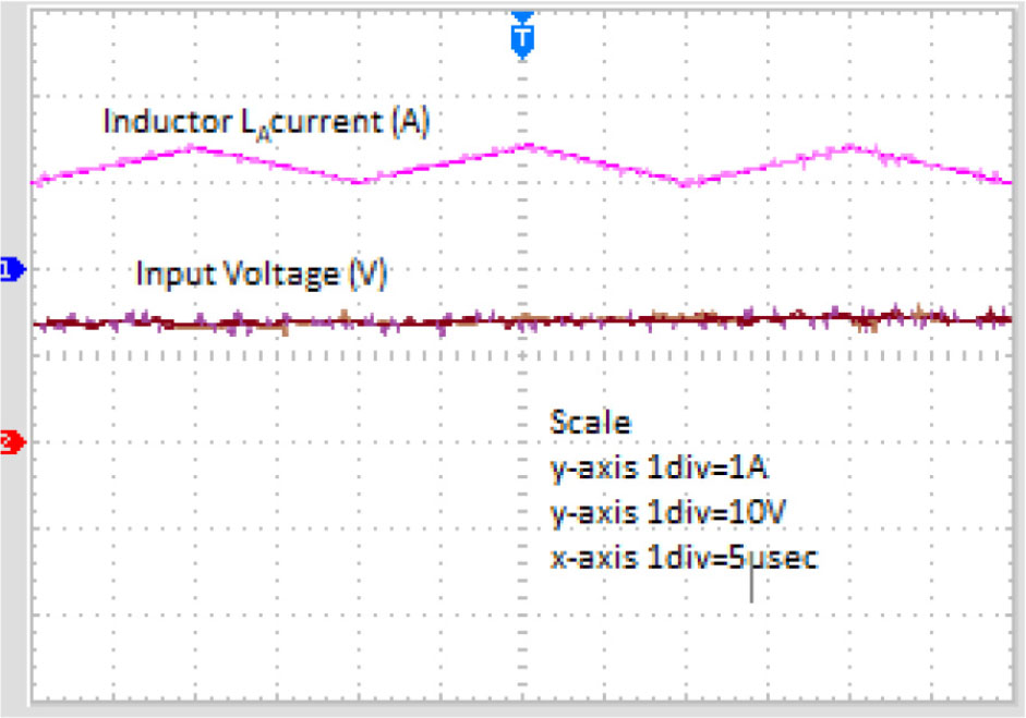
Figure 20:
Input current and inductor LA current.
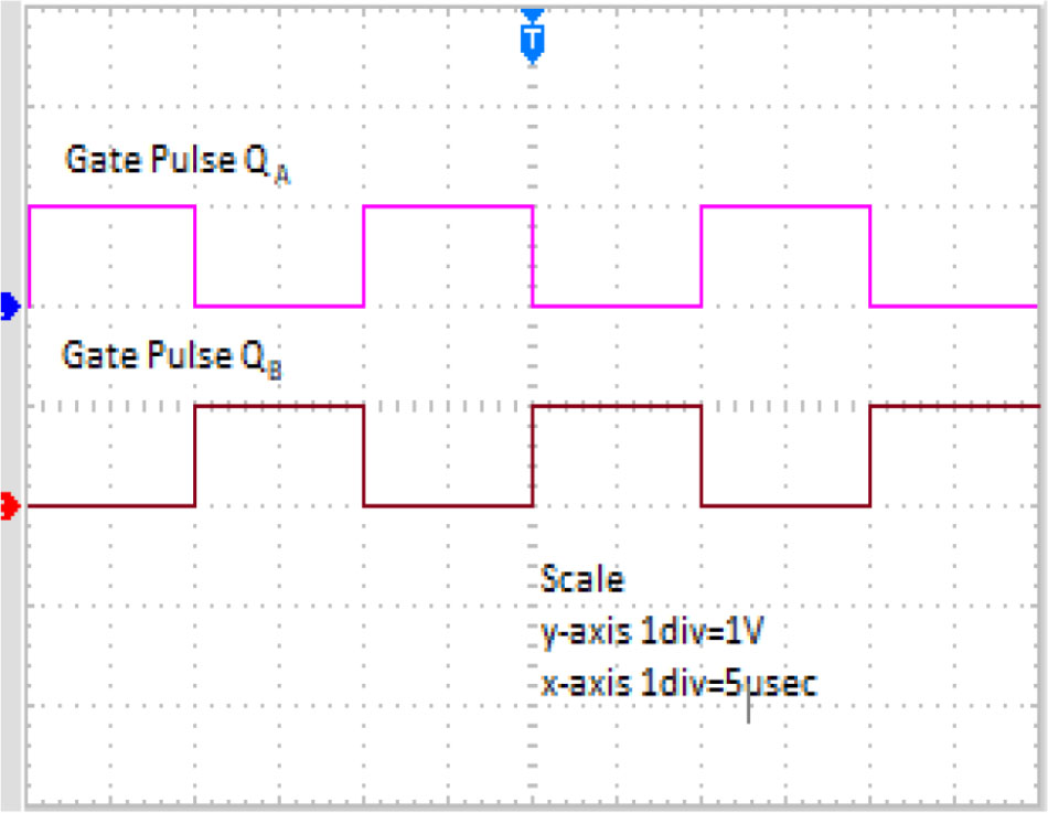
Figure 21:
Gate pulses (QA and QB).
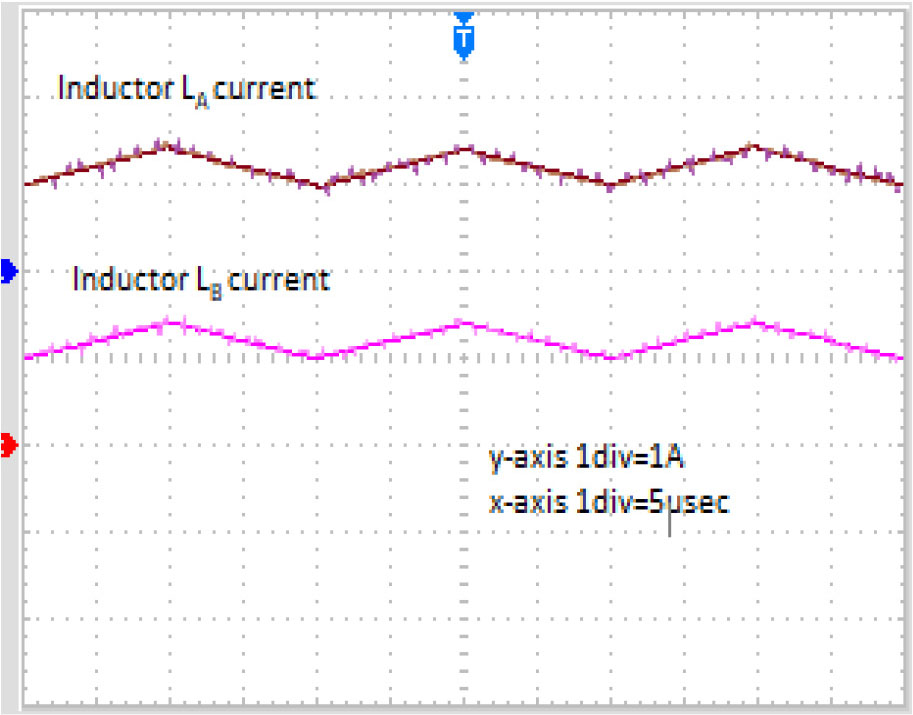
Figure 22:
Inductor currents (LA and LB).
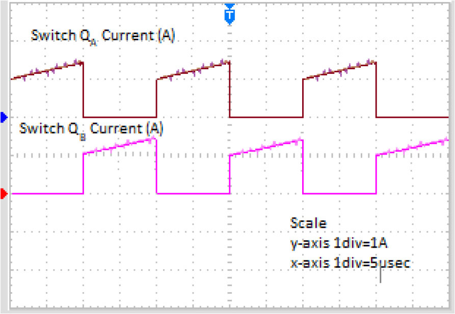
Figure 23:
Switch currents (QA and QB).
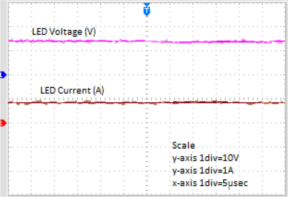
Figure 24:
LED current and LED voltage.
Embedded C coding